Table of Contents
Advertisement
Quick Links
Doc. No. LES*-OMZ0014
PRODUCT NAME
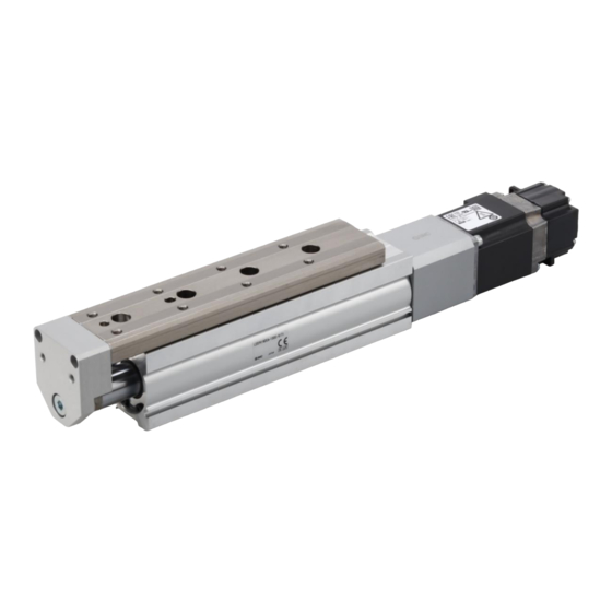
Electric Slide Table / High Precision Type
《 AC servo motor》
MODEL / Series / Product Number
LESYH Series
Applicable models : LESYH(16,25)
#This manual describes the actuators operation in combination with the LECS□ / LECY□ series
drivers.
#Refer to the manual relevant to the controller being used for full operating instructions.
Advertisement
Table of Contents

Related Manuals for SMC Networks LESYH Series


Summary of Contents for SMC Networks LESYH Series
- Page 1 PRODUCT NAME Electric Slide Table / High Precision Type 《 AC servo motor》 MODEL / Series / Product Number LESYH Series Applicable models : LESYH(16,25) #This manual describes the actuators operation in combination with the LECS□ / LECY□ series drivers.
-
Page 2: Table Of Contents
2.11 Power Supply ................19 2.12 Grounding ................19 2.13 Wiring ..................19 2.14 Maintenance ................20 3. LESYH series electric slide table / Common precautions ....21 3.1 Design / selection............... 21 3.2 Handling ..................21 3.3 Precaution on maintenance ............23... -
Page 3: Safety Instructions
LESYH Series / Electric Slide table Safety Instructions These safety instructions are intended to prevent hazardous situations and/or equipment damage. These instructions indicate the level of potential hazard with the labels of “Caution,” “Warning” or “Danger.” They are all important notes for safety and must be followed in addition to International Standards (ISO/IEC) , and other safety regulations. - Page 4 LESYH Series / Electric Slide table Safety Instructions Caution The product is provided for use in manufacturing industries. The product herein described is basically provided for peaceful use in manufacturing industries. If considering using the product in other industries, consult SMC beforehand and exchange specifications or a contract if necessary.
-
Page 5: Specification
1. Specification 1.1 LECS□ series driver 1.1.1 How to order L E S Y H 16 (10) (3)Motor type (1) Size (2)Motor mouting position Output In-line Symbol type Size Compatible driver Right side parallel AC servo motor LECSA□-S1 Left side parallel LECSA□-S3 (Incremental encoder) LECSB2-T5... - Page 6 1.1.2 Specification LESYH*(D,R,L)*(S2/S3) ・・・ Motor type S2/S3 LESYH25R/LS3 LESYH25DS3 Model LESYH16*S2 (Parallel) (In-line) Stroke[mm] 50,100 50,100,150 50,100,150 Horizontal Max. work load [kg] Vertical 65 to 131 127 to 255 79 to 157 154 to 308 98 to 197 192 to 385 Force [N] (Set value: 15 to 30%) Max.
- Page 7 LESYH*(D,R,L)*(T6/T7) ・・・ Motor type T6/T7 LESYH25R/LT7 LESYH25DT7 Model LESYH16*T6 (Parallel) (In-line) Stroke[mm] 50,100 50,100,150 50,100,150 Horizontal Max. work load [kg] Vertical 65 to 131 127 to 255 79 to 157 154 to 308 98 to 197 192 to 385 Force [N](Set value: 12 to 24%) Max.
-
Page 8: Lecy□ Series Driver
1.2 LECY□ series driver 1.2.1 How to order L E S Y H 16 (10) (3)Motor type (2)Motor mouting position (1) Size Output In-line Symbol type Size Compatible driver Right side parallel LECYM2-V5 Left side parallel AC servo motor LECYU2-V5 LECYM2-V7 (Absolute encoder) LECYU2-V7... -
Page 9: Specification
1.2.2 Specification LESYH*(D,R,L)*V ・・・ Motor type V6/V7 LESYH25R/LV7 LESYH25DV7 Model LESYH16*V6 (Parallel) (In-line) Stroke[mm] 50,100 50,100,150 50,100,150 Horizontal Max. work load [kg] Vertical 65 to 131 127 to 255 79 to 157 154 to 308 98 to 197 192 to 385 Force [N](Set value: 45 to 90%) Max. -
Page 10: Construction
1.3 Construction LESYH*R / LESYH*L R type as shown L type opposite as shown Cables includid (D type) Component parts Description Material Remarks Description Material Remarks Body Aluminum alloy Hard anodized Spider Teble Stainless Cover Resin Guide block Steel alloy Return guide Resin Ball screw shaft... -
Page 11: Electric Actuators / Common Precautions
2. Electric actuators / Common precautions 2.1 Wiring/Cables Warning Adjustment, installation, inspection, or wiring changes should be conducted after the power supply to this product has been turned off. Electrical shock, malfunction, or damage can result. Never disassemble the cable. Use only the specified cables. Never connect or disconnect the cable or connector with the power on. -
Page 12: Design/Selection
Insulation failure (interference with other circuits, poor insulation between terminals, etc.) could introduce excessive voltage or current to the controller or its peripheral devices, causing damage to them. 11. The speed and force may change depending on the cable length, load, and mounting conditions. -
Page 13: Mounting
box, as the emergency stop of the system. The stop signals, “EMG” of the controller and the stop switch on the teaching box, are for decelerating and stopping the actuator. Design the system with an emergency stop circuit which applies to the relevant safety standards separately. -
Page 14: Handling
a way that there is no interference at any point within the stroke. Do not scratch or dent the sliding parts of the product tube, piston rod, etc., by striking or grasping them with other objects. The com- ponents are manufactured to precise tolerances. Even a slight deformation may cause a malfunction or seizure. - Page 15 Abnormal noises or vibrations may mean that the product is not properly mounted, and if allowed to continue in this state, damage to the equipment may occur. Never touch the rotating parts of the motor while in operation. Before installing, adjusting, inspecting, or performing maintenance on the product, controller, and related equip- ment, be sure to shut off the power supply.
-
Page 16: Operating Environment
The cross-sectional area of this wire shall be a minimum of 2 mm2. Avoid common grounding with other devices. Other device Actuator Other device Actuator Groundi n g Recommended: Ground Not recommended: Common ground ground 【Unpackaging】 Caution Check that the received product is as ordered. If a product different from the one ordered is installed, injury or damage can result. -
Page 17: Maintenance
Store in an area that is shaded from direct sunlight and has a temperature and humidity within the specified range (–10 C to 60 C and 35 to 85% no condensation or freezing). Do not apply vibration or impact to the product during storage. 2.6 Maintenance Warning Do not disassemble or repair the product. -
Page 18: Design/Selection
Do not apply liquid, oil, or grease to the lock or the area surrounding it. When liquid, oil, or grease are adhered to the sliding parts of the lock, its holding force will reduce significantly. Any changes in lock sliding performance and condition may cause a lock release malfunction. -
Page 19: Mounting
An electric shock, fire, or injury may result. Use only the specified combination between the elec- tric actuator and controller. Failure to do so may cause damage to the actuator or the controller. Be careful not to be hit by workpieces while the actua- tor is moving. It may cause an injury. -
Page 20: Power Supply
Do not install the product in a place subject to vibra- tions and impacts. It will cause failure or malfunction. Do not mount the controller and its peripheral devices together with a large-sized electromagnetic contactor or no-fuse breaker, which generate vibration, on the same panel. Mount them on different panels, or keep the controller and its peripheral devices away from such a vibration source. -
Page 21: Maintenance
Insulation failure (interference with other circuits, poor insulation between terminals, etc.) could introduce excessive voltage or current to the controller or its peripheral devices and damage them. 2.14 Maintenance Warning Perform a maintenance and inspection periodically. Confirm wiring and screws are not loose. Loose screws or wires may cause unintentional malfunction. Conduct an appropriate functional inspection after completing the maintenance and inspection. -
Page 22: Lesyh Series Electric Slide Table / Common Precautions
3. LESYH series electric slide table / Common precautions 3.1 Design / selection Warning Do not apply a load in excess of the actuator specification. A product should be selected based on the maximum pay load and allowable moment. If the... - Page 23 11. When the fluctuation of load is caused during operation, malfunction/noise/alarm may occur. The tuning of gain may not suit for fluctuation load. Adjust the gain properly by following the manual of driver. 12. When mounting the product, use screws with adequate length and tighten them to the maximum torque or less.
-
Page 24: Precaution On Maintenance
15. When the table operates, the gap can be done between actuator (figure below arrow part).Do not place the hand and the finger, etc. because it is dangerous and do not crowd. 16. The product should be mounted as shown below in the figures marked with the ○. Unstable mounting of the product may cause operation failure, generation of abnormal noise or increase in the deflection etc. -
Page 25: Troubleshooting
[Items for visual appearance check] 1. Loose screws. Abnormal dirt. 2. Check of flaws/faults and cable connections. 3. Vibration, noise. [Items for belt check] If there is an abnormal phenomenon of the belt as shown below, stop operation immediately and replace the belt. - Page 26 Revision history NO.LES*-OMZ0014 May / 2021 First edition 4-14-1, Sotokanda, Chiyoda-ku, Tokyo 101-0021 JAPAN Tel: + 81 3 5207 8249 Fax: +81 3 5298 5362 https://www.smcworld.com Note: Specifications are subject to change without prior notice and any obligation on the part of the manufacturer. ©...
Need help?
Do you have a question about the LESYH Series and is the answer not in the manual?
Questions and answers