
Related Manuals for SMC Networks IN-777 Series


Summary of Contents for SMC Networks IN-777 Series
- Page 1 Document No.:K35-OMW0031-A PRODUCT NAME Air Servo Cylinder For HART Communication MODEL/ Series/ Product Number IN-777--F-H...
-
Page 2: Table Of Contents
Contents Contents ................................2 Safety Instructions .............................. 3 1. Introduction ..............................5 2. Specifications ..............................5 3. Function of HART Communication ......................... 5 4. Menu Tree ..............................6 5. Parameter Comparison ..........................7 6. Confirmation and Change of Device Information ................... 8 7. -
Page 3: Safety Instructions
Safety Instructions These safety instructions are intended to prevent hazardous situations and/or equipment damage. These instructions indicate the level of potential hazard with the labels of “Caution,” “Warning” or “Danger.” They are all important notes for safety and must be followed in addition to International Standards (ISO/IEC) , and other safety regulations. - Page 4 Safety Instructions Caution The product is provided for use in manufacturing industries. The product herein described is basically provided for peaceful use in manufacturing industries. If considering using the product in other industries, consult SMC beforehand and exchange specifications or a contract if necessary. If anything is unclear, contact your nearest sales branch.
-
Page 5: Introduction
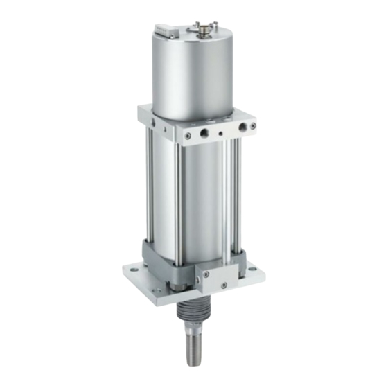
1. Introduction This operation manual applies to the Air Servo Cylinder HART communication specifications (Product No.: IN-777--F--H) IN-777 Air Servo Cylinder provides HART protocol communication as an option. Calibration, operation setting, and data confirmation become available by using 475 field communicator. Refer the manual of EMERSON for the operation. -
Page 6: Menu Tree
4. Menu Tree 1 Device setup 1 Process 1 PV 1 Air servo 1 Device ID variables 2 PV Loop current cylinder data 2 Model 2 Diag/ 3 SV 2 HART data 3 Manufacture Service 4 Manufacture date 3 Detailed 5 Device name setup 1 Operation... -
Page 7: Parameter Comparison
5. Parameter Comparison In HART communication parameter setting items, there are items which function is the same as button operation of the main unit, but different description. Table 2 shows the comparison of expression of Operation manual "Air Servo Cylinder (No.K35-OMW0030)" and the expression of 475 field communicator. Refer "4. -
Page 8: Confirmation And Change Of Device Information
6. Confirmation and Change of Device Information Checking and changing of the equipment information Items Explanation Device ID You can check the ID information of the Air Servo Cylinder board. Model You can check the product classification of the Air Servo Cylinder. Manufacture You can check the manufacturer's ID. - Page 9 Setting and checking of the parameter Items Explanation Operation mode (1) 4-20mA You can switch the mode to 4-20mA, JOG, or Parameter. (2) JOG You can check the current setting mode. (3) Parameter Direction You can set the operating direction. The setting is available only in Parameter mode.
- Page 10 JOG operation command Item Explanation JOG operation You can start / stop the JOG operation. It is necessary to set the mode (page 5) to JOG mode. The operating speed is 50 mm/s constantly. Checking of the operating conditions Items Explanation Loop current You can check the current value input to the air servo cylinder.
- Page 11 (Recording example) 30 h Piston rod Retract end Output current Piston movement Total time (h) Display time (h) Moving area value ~4.8mA 3.125 5~10% 4.8~5.6mA 0.625 10~30% 5.6~8.8mA 30~50% 8.8~12mA 6.25 50~70% 12~15.2mA 70~90% 15.2~18.4mA 90~95% 18.4~19.2mA 1.875 100% 95%~ 19.2mA~ 5.625 Extended end (Set point by calibration)
-
Page 12: Hart Communication
7. HART Communication Caution 1. Refer 475 field communicator manual from EMERSON for 475 field communication usage. 2. Unless input current 4 to 20mADC is supplied to IN-777 Air Servo Cylinder, HART communication is not available. ■IN-777 Air Servo Cylinder This manual describes the version below. -
Page 13: Electrical Wiring
8. Electrical wiring Perform wiring according to the connector pin numbers and the wiring diagram. 1. Connector pin numbers (Male side) M23 19pin/Male Input/output Pin No. Signal name Description status Sig-in+ Input 4-20mA analog input signal (+) with HART Sig-in- Input 4-20mA analog input signal (-) with HART JOG operation signal... - Page 14 2. Wiring diagram (Number in brackets indicates the pin numbers) (5) PWR_24VDC Main circuit (6) PWR_GND (1) Sig-in+ 250 Ω (2) Sig-in- Product number: IN-777--F-H FIELD COMMUNICATOR...
-
Page 15: Hart Communication Method
9. HART Communication Method Caution Confirm followings before starting HART communication. 1. Air Servo Cylinder IN-777 is supplied with 24V as input voltage. 2. Air Servo Cylinder IN-777 is supplied with 4 to 20mA as input current. 3. 475 field communicator wiring is arranged. 4. -
Page 16: Setting
10. Setting This model performs setting of normal/reversed switching of the piston rod travel direction during the target position operation; cylinder bore size, piston rod operating direction at no signal operation and piston rod speed during the target position operation by Air Servo Cylinder switch and HART communication. -
Page 17: Operation Mode And Functions
11. Operation Mode and Functions This model can set the JOG operation, Calibration and Emergency stop by Air Servo Cylinder signal input and HART communication. The operation with each method is explained below. 1. JOG operation, Calibration and Emergency stop operation by Air Servo Cylinder input signal When JOG operation and Calibration are performed by Air Servo Cylinder input signal, set the operation mode (Menu Tree No.1-3-5-2) to 4-20mA. -
Page 18: Error Status
14. Error status Error status (Menu Tree No.1-3-4) and the descriptions are shown below. Error Error name Possible causes Countermeasures code No error The power supply voltage between Power supply error the power supply terminal PWR_24V Use a power supply (Outside of 24 V+/-10%) and PWR_GND is outside of 24 VDC voltage of 24 VDC+/-10%. -
Page 19: Trouble Shooting
15. Trouble shooting If any irregular operation is found during the usage of this Air Servo Cylinder, perform countermeasures in the below table of troubleshooting. For troubles due to cause other than HART communication, refer "9. Trouble Shooting" of operation manual of "Air Servo Cylinder (No.K35-OMW0030)". Content Possible cause Countermeasure... - Page 20 Revision history 4-14-1, Sotokanda, Chiyoda-ku, Tokyo 101-0021 JAPAN Tel: + 81 3 5207 8249 Fax: +81 3 5298 5362 URL http://www.smcworld.com NOTE: Specifications are subject to change without prior notice and any obligation on the part of the manufacturer. © 2019 SMC Corporation All Rights Reserved...
Need help?
Do you have a question about the IN-777 Series and is the answer not in the manual?
Questions and answers