
Related Manuals for Celco Spider67

Summary of Contents for Celco Spider67
- Page 1 Spider67 I/O Module ----Profinet System Manual ELCO (Tianjin) Electronics Co., Ltd 04/2019 Version 1.5...
-
Page 2: Preface
Preface 1. Scope of this manual: This manual applies to the ELCO Profinet Spider67 distributed I/O device. The information in this manual enables you to run the Spider67 module on Profinet in a distributed I/O device. 2. Basic knowledge requirements... -
Page 3: Table Of Contents
3.3 Assigning names in PROFINET IO devices ................... 20 3.3.1 Assigning names by Step7 ......................20 3.3.2 Assigning names by Portal ......................21 3.4 Wiring Spider67.......................... 23 3.4.1 Connecting Spider67 to protective earth (PE) ................. 23 Spider67 Profinet– Extensible industrial fieldbus I/O System 3 / 62... - Page 4 3.4.2 Spider67 power supply ......................23 3.4.3 Spider67 BUS connection ......................25 3.4.4 Spider67 digital signal connection ................... 26 3.4.5 Spider67 analog signal ......................29 4.1 Installation of configuration files ....................33 4.2 Signal address assignment......................35 4.3 Instruction of Analog Value ......................38 4.4 Module Startup Process ......................
-
Page 5: Product Overview
ELCO Spider67 exactly complies this tendency and represents a revolutionary new generation of I/O solutions. Spider67 is an expandable industrial fieldbus I/O product with protection class IP67. It supports standard industrial bus protocol gateways (such as Profibus-DP, Profinet, EtherCAT, CC-Link) and diversified extended I/O configuration modules and can easily be connected to PLC systems. -
Page 6: Type
8-female, M8 interface, 3-pin 8DO, 2A each channel SPDB-0006D-001 1-male, M12 A-Code interface 3-female,M12 A-Code interface SPDB-0300A-001 0~20mA, 4~20mA, ±20mA optional 3-female, M12 A-Code interface SPDB-0300A-002 0~10V, ±10V optional 3-female, M12 A-Code interface Spider67 Profinet– Extensible industrial fieldbus I/O System 6 / 62... - Page 7 BB6S30P03Mxxx Customized length, D=cm,M=dm Pre-wired extensible cable(long distance BB6S30P09Dxxx communication) BB6S30P09Mxxx PVC, 5-core shielded, outer diameter 8mm Customized length, D=cm,M=dm Extension terminal resistance BB6S06 Connecting to the last I/O module Spider67 Profinet– Extensible industrial fieldbus I/O System 7 / 62...
-
Page 8: Technical Characteristics
IP address via the configuration tool, it also can automatically assign IP addresses by PLC according to the network topology. Each Spider67 gateway can connect up to 24 I/O modules via extended port; sort the modules for 1~24 according to the sequence of the connected extension port and the gateway distance from near to far, and configure in... -
Page 9: I/O Module
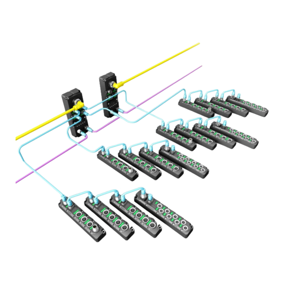
1 cable for communication and power supply I/O interface: 4×M12 8×M8 I/O modules of Spider67 are serial connected, and are connected to In of 1 module by extension cable, then Out of 1 module to In of 2 , up to 6 modules. -
Page 10: Extension Cable
2.3 Extension cable Spider67 extension cable is used between gateways and I/O modules. The overall cable length from the extension interface to the last module is less than 100m . P01 series cable is the standard extension cable. P09 series long distance... -
Page 11: Hardware
Operation current <200mA Max. output current 6A/channel,total for gateway 8A Operation temperature -25℃…70℃ Storage temperature -40℃…85℃ Shock resistance grade Comply with IEC60068-2-6 EN 61000-6-2 Protection class IP67 Operating life 100,000 hours Spider67 Profinet– Extensible industrial fieldbus I/O System 11 / 62... -
Page 12: Digital Io Module
Holding current 200mA,Action current 400mA Supply current Normal input 24VDC (10~30V) voltage Operation -25℃…70℃ temperature Storage -40℃…85℃ temperature Anti-vibration IEC60068-2-6 Class Anti-interference EN 61000-6-2 Protection class IP67 Operating life 100,000 hours Spider67 Profinet– Extensible industrial fieldbus I/O System 12 / 62... -
Page 13: Analog Io Module
Resolution 14Bit Measurement ±0.3% accuracy Input point Max. 200mA Supply current Operation -25℃…70℃ temperature Storage -40℃…85℃ temperature Anti-vibration IEC60068-2-6 Class EN 61000-6-2 Protection class IP67 Operating life 100,000 hours Spider67 Profinet– Extensible industrial fieldbus I/O System 13 / 62... -
Page 14: Rtd And Tc Module
Resolution 14Bit Measurement ±0.2% accuracy Input point Max. 200mA Supply current Operation -25℃…70℃ temperature Storage -40℃…85℃ temperature Anti-vibration IEC60068-2-6 Class EN 61000-6-2 Protection class IP67 Operating life 100,000 hours Spider67 Profinet– Extensible industrial fieldbus I/O System 14 / 62... -
Page 15: Led Display
2.5 LED display Gateway display Extension communication indication Extension power supply indication Gateway status indication Profinet indication indication Profinet indication indication Spider67 Profinet– Extensible industrial fieldbus I/O System 15 / 62... - Page 16 I/O module display Address assignment output indication Address assignment input indication Module status indication Extension communication indication Signal/status indication Spider67 Profinet– Extensible industrial fieldbus I/O System 16 / 62...
-
Page 17: Installing
3. Installing 3.1 Mounting dimensions 3.1.1 Gateway dimensions Spider67 Profinet– Extensible industrial fieldbus I/O System 17 / 62... -
Page 18: Module Dimensions
3.1.2 Module dimensions Spider67 Profinet– Extensible industrial fieldbus I/O System 18 / 62... -
Page 19: Mounting Position And Dimensions
3.2 Mounting position and dimensions Spider67 can be mounted in any position. The following table shows the mounting dimensions of Spider67 gateway and I/O module. Gateway I/O module Mounting width 60mm 30mm Mounting height 165mm 155mm Mounting depth 39mm (without connector) 33.5mm (without connector) -
Page 20: Assigning Names In Profinet Io Devices
3) In the pop-up window, click Browse button, select the Spider67 gateway via the MAC address to assign device name and confirm. 4) Assign the device name for Spider67 module by clicking button Assign Name in the dialog "Edit Ethernet Node". -
Page 21: Assigning Names By Portal
"Assign IP Configuration". (IP address assignment can also be carried out during configuration of the I/O Devices) 6) Now, with the new assigned device name as an identifier of the Spider67 module, you can configure and debug in the program. - Page 22 Note: the MAC address of the Spider67gateway in form of laser engraving or label marked on the side of the module, the device name of the Spider67 gateway will be displayed on the scrolling LED screen (normally, the new assigned device name can be correctly displayed after power on again).
-
Page 23: Wiring Spider67
Always make sure you have a low-impedance connection to protective earth. 3.4.2 Spider67 power supply Proposal: Spider67 series gateway uses 24VDC power supply, I/O module power supply by extensible cable, voltage range 18~30VDC, standard 7/8” connector. Two parts for power supply: gateway module power supply U (1L+, 1M), signal module power supply (2L+, 2M). - Page 24 The six-point output module of Spider67, SPDB-0006D-001 supports auxiliary power supply to the load. The single output point can up to 2A, and the whole module can up to 8A. This power supply interface also uses standard 24VDC power supply and M12 A-Code standard interface.
-
Page 25: Spider67 Bus Connection
3.4.3 Spider67 BUS connection Spider67 gateway, supporting Profinet protocol, transmits signals by a shielded cable, D-Code M12 connector. 1)BUS-In (Female) 2)BUS-Out (Female) 3)Bus definition Terminal Function Cable color Transmit Data( TD+ ) Yellow Receive Data( RD+ ) White Transmit Data( TD- ) -
Page 26: Spider67 Digital Signal Connection
3.4.4 Spider67 digital signal connection Spider67 digital I/O modules are connected by standard 5-pin M12 or 3-pin M8 connector, max. 2 signals (input or output) can be connected to M12 interface, 1 signal (input or output) can be connected to M8 interface. - Page 27 Double input signal – 1 connector connects 2 DI, SPDB-0800D-001, SPDB-0404D-001, and SPDB-08UP-001 support this connection. b) Double output signal – 1 connector connects 2 DO, SPDB-0008D-001, SPDB-0404D-001, SPDB-08UP-001, SPDB-0006D-001 support this connection. Spider67 Profinet– Extensible industrial fieldbus I/O System 27 / 62...
- Page 28 Single input signal – 1 connector connects 1 DI, SPDB-0800D-011, SPDB-0404D-011, SPDB-08UP-011 support this connection. e) Single output signal – 1 connector connects 1 DO, SPDB-0404D-011, SPDB-0008D-011, SPDB-08UP-011 support this connection. Spider67 Profinet– Extensible industrial fieldbus I/O System 28 / 62...
-
Page 29: Spider67 Analog Signal
3.4.5 Spider67 analog signal Spider67 analog I/O modules are connected by standard 5-pin M12, 1 signal (input or output) can be connected to interface. 1)Signal receiving (Female) 2)Analog signal interface definition Terminal Function Function Power supply 24V+ Signal in/out +... - Page 30 4-wire input - 1 connector connects 1 4-wire input, SPDB-0300A-001 supports this connection. c) Voltage input- 1 connector connects 1 voltage input, SPDB-0300A-002 supports this connection. Spider67 Profinet– Extensible industrial fieldbus I/O System 30 / 62...
- Page 31 Two-wire thermal resistance signal — 1 connector connects 1 two-wire thermal resistance input signal, the model SPDB-0400A-005 of the signal module supports this form of connection. Spider67 Profinet– Extensible industrial fieldbus I/O System 31 / 62...
- Page 32 SPDB-0400A-005 of the signal module supports this form of connection. i) Thermocouple signal —1 connector connects 1 thermocouple input signal, the model SPDB-0400A-006 of the signal module supports this form of connection. Spider67 Profinet– Extensible industrial fieldbus I/O System 32 / 62...
-
Page 33: Installation Of Configuration Files
Configuration of the spider67 distributed I/O device via GSD file (XML format) and the standard Profinet IO GSD file for the Spider67 will be integrated into the user’s system. You can visit the ELCO website to get the latest GSD file or call the hotline to contact technical support. - Page 34 The new additional Spider67 module is shown in the directory of hardware ”Additional Field Devices>I/O>Spider 67 Gateway>Spider67 Gateway Module” 4) The user can configure the Spider67 module with Step7 according to the actual situation. Spider67 Profinet– Extensible industrial fieldbus I/O System...
-
Page 35: Signal Address Assignment
P3.Pin4 Q 0.3 Bit 4 P2.Pin4 P4.Pin4 Q 0.4 Output Bit 5 P2.Pin2 P5.Pin4 Q 0.5 Bit 6 P3.Pin4 P6.Pin4 Q 0.6 Byte 0 Bit 7 P3.Pin2 P7.Pin4 Q 0.7 Spider67 Profinet– Extensible industrial fieldbus I/O System 35 / 62... - Page 36 P1.Pin2 P3.Pin4 Q 0.3 Bit 4 P2.Pin4 P4.Pin4 Q 0.4 Byte 0 Bit 5 P2.Pin2 P5.Pin4 Q 0.5 Bit 6 P3.Pin4 P6.Pin4 Q 0.6 Bit 7 P3.Pin2 P7.Pin4 Q 0.7 Spider67 Profinet– Extensible industrial fieldbus I/O System 36 / 62...
- Page 37 The module occupies 6 bytes for output. Byte Byte Connector e.g. Byte 0 QW 0 Byte 1 Output Byte 2 QW 2 Byte 3 Byte 0~5 Byte 4 QW 4 Byte 5 Spider67 Profinet– Extensible industrial fieldbus I/O System 37 / 62...
-
Page 38: Instruction Of Analog Value
±5V and ±10V; current unipolar value 0~20mA and 4~20mA; voltage unipolar value 0~5V and 0~10V. Note: Analog output only supports rated analog value; overshoot range only represents input module. Spider67 Profinet– Extensible industrial fieldbus I/O System 38 / 62... - Page 39 AF00 -3.75 V -7.5 V -100% -27648 9400 -5 V -10 V -27649 93FF Overshoot range -118.519% -32768 8000 ≤ -5.926 V ≤ 11.85 V Underflow, lock the least value Spider67 Profinet– Extensible industrial fieldbus I/O System 39 / 62...
- Page 40 6C00 10 V 20736 5100 3.75 V 7.5 V Rated range 0.003617% 1 FFFF -75% -20736 AF00 -100% -27648 9400 Underflow, lock the least value -27649 93FF -118.519% -32768 8000 Spider67 Profinet– Extensible industrial fieldbus I/O System 40 / 62...
- Page 41 637.5 ℃ 6375 18E7 1 ℃ 0 ℃ Rated range -1 ℃ FFF6 -150 ℃ -1500 FA24 -200 ℃ -2000 F830 ≤ -200.1 ℃ -32768 8000 Underflow, lock the least value Spider67 Profinet– Extensible industrial fieldbus I/O System 41 / 62...
- Page 42 10, the current temperature can be obtained. The resolution is 0.1 C, and the maximum or minimum value can be locked out beyond the limit. Spider67 Profinet– Extensible industrial fieldbus I/O System 42 / 62...
-
Page 43: Module Startup Process
4.4 Module Startup Process Check whether the following requirements are met for the startup of the Spider67 distribution I/O module system: Spider67 gateway and module are power, bus and signal wired. The module address is set by software. -
Page 44: Module Configuration By Step7
This section, through a case of connection configuration in a current operation process, will let the users fully understand how to use the Spider67 distribution I/O system. In this case, using the ELCO spider67 as PROFINET slave station to connect... - Page 45 2) Insert a new SIMATIC 300 Station 3) Double click “Hardware” button to start the hardware configuration tool. Spider67 Profinet– Extensible industrial fieldbus I/O System 45 / 62...
- Page 46 4) Install the GSD file according to section 4.1 5) Change the hardware configuration, select the appropriate slot, power supply and CPU in the Catalog window, and set the properties of the CPU, bus etc. Spider67 Profinet– Extensible industrial fieldbus I/O System 46 / 62...
- Page 47 6) According to Section 3.3 user guide, select "PLC Edit Ethernet > Ethernet > Node", assign the Spider67 gateway device the name of elco67 in the pop-up window . 7) In the Catalog window, the catalog of "Profinet IO>Additional Field Devices>I/O>Spider 67 Gateway>Spider67 Gateway Module", select the...
- Page 48 8) Double click on the newly added Spider67 gateway, fill in the previously setting device name elco67 in the pop-up "properties" window, and assign IP address to this module via the "Ethernet.." button: 192.168.0.15. Be sure to click the option "assign IP via IO controller" .
- Page 49 9) Based on the I/O module configuration described in the beginning of this section, we add the module type and quantity to each slot position of Spider67 gateway in the catalog window, from the directory "SPPN-GW-001" according to the sequence of the extension port P0-P1-P2-P3 and assign the input and output address.
- Page 50 The user can select the current input type of each signal port: "0~20mA", "4~20mA", "-20~+20mA", you can also close the port to improve the sample scanning speed of this module. Spider67 Profinet– Extensible industrial fieldbus I/O System 50 / 62...
- Page 51 "0~10V", "-10~+10V", "0~5V", "-5~+5V", you can also close the port to improve the sample scanning speed of this module. 13) Save the compilation and download configuration to the PLC, until now the configuration is completed. Spider67 Profinet– Extensible industrial fieldbus I/O System 51 / 62...
-
Page 52: Module Configuration By Portal
This section, through a case of connection configuration in a current operation process, will let the users fully understand how to use the Spider67 distribution I/O system. In this case, using the ELCO spider67 as PROFINET slave station to connect... - Page 53 2) Install the GSD files of ELCO Spider67 3) Double-click “Add New Device” and select the PLC type. Spider67 Profinet– Extensible industrial fieldbus I/O System 53 / 62...
- Page 54 IP address of PLC. 5) On the “Network View” tab, select the SPPN-GW-001 gateway of ELCO from the Hardware Directory on the right to add to the network. Spider67 Profinet– Extensible industrial fieldbus I/O System 54 / 62...
- Page 55 Spider67 gateway in the window, and set the IP address. 7) Based on the I/O module configuration described in the beginning of this section, we add the module type and quantity to each slot position of Spider67 gateway in the catalog window, from the directory "SPPN-GW-001" according to the sequence of the extension port P0-P1-P2-P3 and assign the input and output address.
- Page 56 Parameters tab to assign parametersin the new pop-up window. The user can select the current input type of each signal port: "0~20mA", "4~20mA", "-20~+20mA", you can also close the port to improve the sample scanning speed of this module. Spider67 Profinet– Extensible industrial fieldbus I/O System 56 / 62...
- Page 57 Parameters tab to assign parameters in the new pop-up window. The user can select the voltage input type of each signal port: "0~10V", "-10~+10V", "0~5V", "-5~+5V", you can also close the port to improve the sample scanning speed of this module. Spider67 Profinet– Extensible industrial fieldbus I/O System 57 / 62...
- Page 58 11) Save the compilation and download configuration to the PLC, until now the configuration is completed. Spider67 Profinet– Extensible industrial fieldbus I/O System 58 / 62...
-
Page 59: Alarm Diagnosis
5. Alarm diagnosis 5.1 LED fault indicator With the built-in LED on Spider67 distributed I/O module, users can quickly and easily diagnose the working status of module. (Please see Section 2.5 "LED function") Gateway LED Name status Meaning Possible causes... - Page 60 1 The actual output signal does not match with the configuration 2 Signal power supply short circuit Signal abnormal 3.Expansion module damage Signal/Sta 4 Beyond range (analog module) tus LED Green Signal No signal Spider67 Profinet– Extensible industrial fieldbus I/O System 60 / 62...
-
Page 61: Diagnostic Information
The information with additional detailed information includes both the information of the starting interrupt OB and the information of the interrupt source. Call "RALRM" only within the interrupt OB started by the CPU operating system as a Spider67 Profinet– Extensible industrial fieldbus I/O System 61 / 62... - Page 62 In the TINFO and AINFO cache data, you can quickly get the information such as station number, slot number, channel and occurred error type and other information. Spider67 Profinet– Extensible industrial fieldbus I/O System 62 / 62...
Need help?
Do you have a question about the Spider67 and is the answer not in the manual?
Questions and answers