Table of Contents
Advertisement
Quick Links
Advertisement
Table of Contents

Related Manuals for Celco Spider67 Mobile Series

Summary of Contents for Celco Spider67 Mobile Series
- Page 1 Manual Spider67 Mobile series IoT-Gateway...
- Page 2 General information © All rights are reserved by Elco Industrie Automation GmbH, also in case of applications for industrial property rights. We reserve all rights of disposal, such as the right to copy and pass on the material. The frontpage shows an example configuration. The delivered product may therefore differ from the illustration.
- Page 3 General information This document applies to the following products: SPMB-16DIO-001 Digital (16-way) extensible gateway, mobile version SPMB-16DIO-002 Digital (16-way) extensible gateway, WiFi version SPMB-16DIO-003 Digital (16-way) extensible gateway, mobile+WiFi version SPMB-16DIO-012 Current analog input (4-way) gateway, WiFi version SPMB-16DIO-022 Voltage analog input (4-way) gateway, WiFi version Manual number 10001 Language...
-
Page 4: Table Of Contents
General information CONTENTS General information Manufacturer Purpose of this manual Required and supplementary documentation Explanation of symbols and spelling Safety instructions Intended use Unintended use Product safety Requirements for persons performing the work Danger due to electrical voltage Interventions and changes to the unit General description Product characteristics Product series... - Page 5 General information SPMB 16DIO diagnostics SPMB-04AIO diagnostics Application platform Architecture of the standard application of Spider67 Mobile Registration – Login Device Management Cloud - Logical control Maintenance, cleaning, service Maintenance Cleaning Service Transportation, storage, disposal Transportation Storage Disposal Technical data 10.1 SPMB-16DIO 10.2...
-
Page 6: General Information
General information GENERAL INFORMATION Manufacturer Elco Industrie Automation GmbH Benzstrasse 7 71720 Oberstenfeld Tel: +49 7062 6599-260 Fax: +49 7062 6599-261 www.elco-automation.de Purpose of this manual The purpose of this manual is to help users quickly become familiar with and understand the Spider67 Mobile series. -
Page 7: Required And Supplementary Documentation
General information Required and supplementary documentation The following table contains necessary and supplementary documentation for the installation and commissioning of the unit. Document type Description Document no. Operation instruction The operating instruction is supplied with the device or can be found at www.elco-automation.de ... - Page 8 General information The word NOTE indicates a potentially harmful situation for the product or NOTE its environment. The word HINT refers to additional information or application hints. HINT 1.4.2 Used warning and command signs Warning sign General warning sign Warning of electrical voltage Mandatory sign General mandatory sign Refer to the instruction for use...
- Page 9 General information 1.4.3 Instructions for action In the instructions we show you how to proceed to achieve a goal. Action goal Action goal (observe sequence!) Tools and requirements (optional) Tools and requirements (optional) Action step Action step ...
-
Page 10: Safety Instructions
Safety instructions SAFETY INSTRUCTIONS This chapter contains important safety instructions to prevent personal injury and damage to property. Intended use The devices are designed for use in the industrial sector. The Spider67 mobile radio system is a device of EMC class A. It can cause radio interference in residential and mixed areas. -
Page 11: Requirements For Persons Performing The Work
Safety instructions Operation outside the technical specifications of the product (see type plate and technical data) can lead to a defect and cause further damage! The product and its accessories may only be installed and operated in perfect condition and in accordance with the operating instructions. - Page 12 Safety instructions EU Declaration of Conformity 2020/7/V1.0 12 | 68 Manual-No.: 10001_hdb_en...
- Page 13 Safety instructions 2020/7/V1.0 13 | 69 Manual-No.: 10001_hdb_en...
- Page 14 Safety instructions 2020/7/V1.0 14 | 68 Manual-No.: 10001_hdb_en...
-
Page 15: General Description
The Spider67 Mobile series consists of digital and analog gateways and I/O extension modules for the Internet of Things (IoT). The Spider67 Mobile series operates independently of a control unit such as a PLC, NC or other control systems. The logical controller is a self-contained system and runs centrally via the user platform (cloud computing). -
Page 16: Product Characteristics
General description Product characteristics ⚫ Connection: M12 circular connector, protection class IP67 ⚫ Transmission: Mobile radio or WLAN. ⚫ Requires Bluetooth configuration! Configuration as Android or iOS app. ⚫ The SPMB-16DIO-001, SPMB-16DIO-002 and SPMB-16DIO-003 modules allow gateway expansion with a maximum of 6x I/O submodules. ⚫... -
Page 17: Use
3.5.3 Elco-IoTHub All products of the Spider67 Mobile series are factory connected to Elco-IoTHub. The IoTHub is a powerful cloud environment that can be flexibly extended and connected in all directions. The complete data processing takes place in this system. For easier visualisation of the Spider67 Mobile application, Elco provides another web interface (Web-UI), which is the interface between customer and backend. -
Page 18: Hardware Hardware Environment
Hardware HARDWARE Hardware environment ⚫ Server Servers running the IoTHub and the Spider67 Mobile application platform (cloud version, local server version) and related software and network support resources. ⚫ Computer/web access and Android/iOS mobile devices We recommend a computer with a Google Chrome Browser to configure the user platform. An Android or iOS device is required to configure the hardware. - Page 19 Hardware Abb. 2. Example of a network Fig. 2 shows an example of a network with the Spider67 Mobile. The Spider67 Mobile is installed in the field to collect sensor data. The sensor data is transmitted to the IoTHub via mobile radio and stored and processed there. From the IoTHub, Elco provides a standard web interface for configuring the Spider67 Mobile via API.
-
Page 20: Spmb 16Dio Series
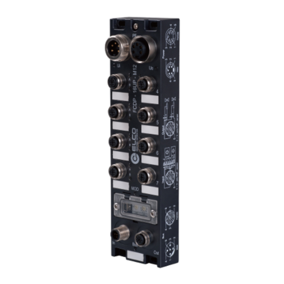
Hardware SPMB 16DIO series Abb. 3 Product picture SPMB 16DIO 8x I/O ports (P0 … P7) for 16 inputs or outputs WLAN antenna Mobile phone antenna Power supply, M12 male, A-coded Status display for the gateway I/O port for forwarding the signals to the expansion module, M12 female, B-coded I/O indication for each port, signal B 4x mounting hole M4... - Page 21 Hardware 4.3.1 Connections 4.3.1.1 I/O connections (siehe Fehler! Verweisquelle konnte nicht gefunden werden. (6)) The SPMB-16DIO has 8 ports for 16 digital transmission channels. Configurations with 16 digital I/O channels can be set using the application platform and configuration tools, including typical I/O modes, as follows: ⚫...
- Page 22 Hardware Turn the PIN indicator 180° clockwise to match the gateway installation diagram. Abb. 5. Connection for power supply (M12 male, A-coded) Pin-no. Pin assignment Information display Module and output +24 V DC bridged Module and output +24 V DC PWR-LED Module and output +24 V DC bridged...
- Page 23 Hardware 4.3.2 I/O extensions The Spider67 Mobile 16DIO series supports a total of 6 digital expansion modules or a maximum of 9 analog ports with a maximum of 3 modules. ATTENTION Device defect due to excessive total current! When connecting the expansion modules, observe the maximum total current of 4 A and power limitation per channel.
- Page 24 Hardware NOTE A maximum of 9 analog ports can be connected to the Spider67 Mobile DIO 4.3.2.3 Example 3: I/O expansion with 2 analog und 2 digital expansion modules Abb. 9 I/O expansion with 2 analog und 2 digital expansion modules 4.3.2.4 Example 4: I/O expansion with 1 analog und 4 digital expansion modules Abb.
- Page 25 Hardware 4.3.3 LED display The multi-channel LED display of the SPMB-16DIO shows the user the operating status of the unit. INFO The LED display is identical in all modules of the SPMB-16DIO series. Abb. 11. Multi-channel LED display 4.3.4 I/O display left and right of the ports Abb.
- Page 26 Hardware 4.3.6 Description of the SPMB-16DIO module To simplify the management of the platform configuration and the protocol definition, the Spider67 Mobile module is defined as 0 ~ X in the standard communication protocol of the IoTHub. NOTE This X is not a fixed value for all application modes, the value depends on the number of final extensions.
- Page 27 Hardware 4.3.7 Port and module numbering To simplify the configuration management, the IoTHub system defines each group of 4 I/O ports as a module by default. The SPMB-16DIO series ports of the P0 ~ P3 gateways are therefore defined as Module_0.
-
Page 28: Spmb 04Aio Series
Hardware SPMB 04AIO series Abb. 15. Product picture SPMB 04AIO WLAN antenna 4x I/O port for 4 inputs (M12 male plug, B-coded) Power supply, M12 male plug, A-coded 2x mounting holes I/O display for each port 4.4.1 Connections 4.4.1.1 I/O connections (siehe 0 (4)) The SPMB-04AIO-Gateways have 4 ports. - Page 29 Hardware SMA antenna connection „WLAN“ 4.4.1.2 (siehe Fehler! Verweisquelle konnte nicht gefunden werden. (1 – WLAN) Connection for voltage supply „PWR“ 4.4.1.3 (siehe Fehler! Verweisquelle konnte nicht gefunden werden. (7)) The interface of the SPMB-04AIO gateway to the power supply is an M12 connector, A-coded. ...
- Page 30 Hardware Abb. 18. Multi-channel LED display Abb. 19. LED display for each port 4.4.3 Expansion of the SPMB-04AIO series NOTE The module is not expandable. P0 … P3 ports of the SPMB-4AIO gateway = module_0 Abb. 20. 4.4.4 SPMB-04AIO series channel description Each port is a separate channel for the digital signal input.
-
Page 31: Assembly And Installation
Assembly and installation ASSEMBLY AND INSTALLATION Dimensions SPMB-16DIO Abb. 21 Dimensions SPMB 16DIO in mm 2020/7/V1.0 31 | 69 Manual-No.: 10001_hdb_en... -
Page 32: Dimensions Spmb-04Aio
Assembly and installation Dimensions SPMB-04AIO Abb. 22. Dimensions SPMB 04AIO in mm 2020/7/V1.0 32 | 68 Manual-No.: 10001_hdb_en... -
Page 33: Mounting Distances
Assembly and installation Mounting distances Abb. 23. Mounting distances SPMB-16DIO SPMB-04AIO 70 mm 70 mm >20 mm >20 mm NOTE Ensure sufficient space for easy module replacement and observe the bending radii of the cables! 2020/7/V1.0 33 | 69 Manual-No.: 10001_hdb_en... -
Page 34: Mounting Requirements
Assembly and installation Mounting requirements ⚫ Mounting location in the field or in the IP67 area, in immediate proximity of the machine/system. ⚫ Any mounting position. ⚫ The mounting location guarantees: ▪ environmental conditions (see chapter 10 Technical data), ▪ flat, solid mounting surface ▪... -
Page 35: Electrical Installation
Assembly and installation Electrical installation WARNING Danger due to electrical voltage! A non-qualified installation can impair the use of the device or lead to damage to the device! Only qualified electrical engineering personnel may install the Spider67 Mobile modules. ... -
Page 36: Wlan Communication (Gateway With Wlan Antenna)
Assembly and installation 5.6.2 I/O connections for sensors/actuators or expansion modules ATTENTION Device defect due to excessive total current! When connecting the expansion modules, observe the maximum total current of 4 A. Connect extension module or sensor to I/O connections ... -
Page 37: Commissioning /Operation
Commissioning /Operation COMMISSIONING /OPERATION NOTE Before you put the device into operation: The device may only be put into operation by trained personnel who comply with all regulations. Make yourself familiar with the safety instructions in chapter 2. Avoid electrostatic charge. - Page 38 Commissioning /Operation Configuration in the Spider67(m)-App Start Spider67 (m)- Tap on the 3 dots in Tap on About: App: the upper right ✓ Display of the version. corner: ✓ Display start screen ✓ About is displayed. ...
- Page 39 Commissioning /Operation Selection in settings Tap on the blue wheel: ✓ Settings of the Spider67 open. Tap on the green list: ✓ More detailed information about the device is displayed. Tap on the blue pen: ✓ You can rename the Spider. ...
-
Page 40: Spmb 16Dio Diagnostics
Commissioning /Operation SPMB 16DIO diagnostics INFO The LED display is identical in all modules of the SPMB-04AIO series. 6.2.1 Multi-channel LED display Abb. 25. Multi-channel LED display Symbol Function Status Function Green Voltage present, function ok Power Error: voltage too high/low or short circuit Power supply signal Green... -
Page 41: Spmb-04Aio Diagnostics
Commissioning /Operation 6.2.2 I/O display left and right of the ports Abb. 26. LED display per port Symbol Status Function Green Signal high B + A Signal low P0 … P7 Error: voltage too high/low or short circuit SPMB-04AIO diagnostics INFO ... - Page 42 Commissioning /Operation Symbol Function Status Function Green Voltage present, function ok Power Power supply Error: voltage too high/low or short circuit Green Signal very good, 100-80% signal strength Signal Device connected, bud bad connection to Orange server or WLAN WLAN-Module Error/not connected Green fast flashing Initialize module...
-
Page 43: Application Platform
Application platform APPLICATION PLATFORM INFO The current platform version is 2.X and can be accessed under the username/ABout. It supports the SPMB-16DIO series. The SPMB-04AIO series will be adapted gradually. Elco will update the relevant platform functions and descriptions according to the product delivery schedule. - Page 44 Application platform Username and password for standard platform Contact the responsible customer manager. ✓ You will receive a username and a password from him. Username and password for customized platform You will find the login address and login information in the delivery manual. RECOMMENDATION Various browsers and operating systems store or record login information.
- Page 45 Application platform 7.2.2 Roles and rights Users can customize the roles and user settings in the IoTHub. Click on Management: Abb. 32. User management button In the user management we distinguish between users (User), groups (Group) and roles (Roles). The Admin can create and manage any number of users. These users do not have any permissions or properties.
- Page 46 Application platform The Scope Assignment sub-item now allows the properties of the role to be freely defined. Furthermore, devices, agents and workflows can also be directly assigned to only one role. Abb. 35. Assigning properties to a role In order to use now the defined properties of the role with the users, a group must be created and the role must be assigned to the group.
- Page 47 Application platform Abb. 37. Displaying all members of the group The Members button can now be used to assign the required members to the group. Abb. 38. Assigning members to the group Abb. 39. Assigning roles to the group 2020/7/V1.0 47 | 69 Manual-No.: 10001_hdb_en...
- Page 48 Application platform The Groups button can now be used to assign the created roles to the group. The members of this group now have these properties 2020/7/V1.0 48 | 68 Manual-No.: 10001_hdb_en...
-
Page 49: Device Management
Application platform Device Management Accessing the page: Menu Things Add Spider67 Abb. 40. Device management The Spider67 Mobile is already automatically recognized and configured by the IoTHub via the agent implemented in the firmware. This makes it much easier for the user to install the device. As soon as the Spider67 Mobile connects to the cloud, its digital twin is created with the local properties. - Page 50 Application platform Abb. 41. IMEI-Nummer und MAC-Adresse Turn on the Spider67 Mobile you want to add. Connect the Spider67 Mobile to the network. NOTE: Requirement for the following steps: The device is switched on and runs stable. Perform the steps of the app installation (see chapter Fehler! Verweisquelle konnte nicht gefunden werden.
- Page 51 Application platform Delete Spider67 Mobile Abb. 43. Delete Spider67 Mobile Click on the button Delete device. The device is deleted from the management platform. NOTE: The deleted device can be added back to the management platform. 7.3.1 Configuration of the Gateway Accessing the function Menu Things >...
- Page 52 Application platform 7.3.2 Switching BLE on and off To guarantee the security of the device locally, the Bluetooth low energy chip can be switched on and off by the software via cloud command. Calling the function Menu Things > Sensor Values From firmware version V3.3 of the Spider67 Mobile, the function of the Bluetooth Low Energy Chip can be deactivated for parameterisation.
-
Page 53: Cloud - Logical Control
Application platform • The channel channel_1 serves as a feedback channel and redundantly displays the status of the chip. This channel only serves as an input for the IoTHub and constantly polls the BLE chip for the function. The remaining channels of the submodule are kept free for customer projects and are not used in the standard unit. - Page 54 Application platform INFO The local logic in the Spider67 Mobile is very economical to use, as this logic is of higher quality than that of the cloud. The local logic always overwrites opposing commands from the cloud and can thus lead to undesired effects. Via the menu Actions &...
- Page 55 Application platform Abb. 48. Logic structure In the code, the green fields can be changed individually by users. The count always starts at 0 and ends at 7. Furthermore, the gateway is divided into two individual sub-modules in the software. Thus the ports P0...P3 belong to module 0 and the ports 4...7 to module 1 Abb.
-
Page 56: Maintenance, Cleaning, Service
Maintenance, cleaning, service MAINTENANCE, CLEANING, SERVICE WARNING Danger to electrical voltage! During operation, certain parts of the device may be under dangerous voltage! Disconnect the device from all energy sources during maintenance and service work (of the machine) and during configuration (the device can remain connected to SELV or PELV circuits). -
Page 57: Transportation, Storage, Disposal
Transportation, storage, disposal TRANSPORTATION, STORAGE, DISPOSAL Transportation The device is provided with protective packaging ex works. Avoid shocks and impacts. If possible, transport the device in its original packaging. Storage If possible, store the device in its original package. ⚫... -
Page 58: Technical Data
Technical data TECHNICAL DATA 10.1 SPMB-16DIO The Spider67 Mobile series SPBM-16DIO supports 16-pin digital input or output connectors for sensors and actuators. Electrical data Function Designation Value Power supply Nominal voltage 24 VDC 10 … 30 VDC ±10% Voltage range... - Page 59 Technical data Radio interface Designation Value Mobile radio Supporter mobile radio TDD-LTE B38/B40/B41 interface FDD-LTE B1/B3/B5/B7/B8/B20 WCDMA/HSDPA/HSPA+ B1/B5/B8 GSM/GPRS/EDGE 900/1800 MHz Sim card eSIM Support external antennas to improve signal quality GSM/GPRS-power GSM/GPRS power class: EGSM900: 4 (2W) DCS1800: 1 (1W) EDGE power EDGE power class: EGSM900: E2 (0.5W)
- Page 60 Technical data Diagnostics Function Designation Value Power supply I/O indictator Left and right of port WLAN or Bluetooth Module Status I/O status Link extension module Tabelle 7: Diagnostics Environmental conditions Function Designation Value -25 ℃ … +70 ℃ Temparature Operation range -35 ℃...
-
Page 61: Spmb-04Aio
Technical data 10.2 SPMB-04AIO The Spider67Mobile series SPMB-04AIO supports 4-pin digital input or output connections for sensors. Electrical data Function Designation Value Power supply Nominal voltage 24 VDC 10 … 30 VDC ±10% Voltage range I/O port Only analog signals 4x M12-socket, A-coded I/O channel Signal connection... - Page 62 Technical data Diagnostics Function Designation Value I/O indicator Left and right of port Power supply WLAN Module status Mobile radio I/O status Link extension module Tabelle 13: Diagnostics Environmental conditions Funcion Designation Value -25 ℃ … +70 ℃ Temperature Operation range -35 ℃...
-
Page 63: Annex
Annex ANNEX 11.1 Approved accessories and spare parts NOTE Only use Elco approved accessories and Elco approved spare parts. 11.2 Spare parts 11.2.1 Mobile radio antenna for SPMB-16DIO series Article name Abbrevation Short description SPMB-ANT01-030 SPMB Spider67 Mobile Antenna Antenna type "LTE"... - Page 64 Annex 11.2.2 WLAN antennas for SPMB-16DIO and SPMB-04AIO-Serie Article name Abbrevation Short description SPMB-ANT02-030 SPMB Spider67 Mobile Antenna Antenna type "WLAN" Cable length 3 m Magnetic base antenna Number Dimensions Drawing 3000,00 mm ±0,5 mm 30,00 mm ±0,2 mm 16,50 mm ±0,2 mm 230,00 mm ±0,2 mm 5 windings 5 windings...
-
Page 65: Accessories
Annex 11.3 Accessories 11.3.1 Extension modules Article name Short description Interfaces SPDB-0003A-001 Analog extension module Spider67 3xM12 3AO, current mode 2xM12 B-coded 0 ... 20mA, 4 ... 20mA SPDB-0003A-002 Analog extension module Spider67 3xM12 3AO, voltage mode 2xM12 B-coded 0 ... +10V SPDB-0004A-001 Analog extension module Spider67 4xM12... -
Page 66: Abbrevations/Glossary
Annex 11.4 Abbrevations/Glossary Entry Description Analog input Analog inputs and outputs Analog output Access Point (AP) – (wireless) access point or base station Application Programming Interface (API), interface for programming applications Application software (App) Bluetooth Low Energy, Bluetooth LE Chrome Google Chrome is a (freeware) web browser from the US company Google LLC dB (decibel) is the unit of power level Power level with reference 1 mW... - Page 67 Annex Modbus/TCP Modbus TCP/IP is a client/server protocol for the secure exchange of process data. MQTT Message Queuing Telemetry Transport (MQTT) is an open message protocol for machine-to-machine (M2M) communication. n. c. Not connected PELV Protective Extra Low Voltage PNP switches ground to the output of the sensor Pre-Shared-Keys –...
-
Page 68: Notes
Notes NOTES 2020/7/V1.0 68 | 68 Manual-No.: 10001_hdb_en...
Need help?
Do you have a question about the Spider67 Mobile Series and is the answer not in the manual?
Questions and answers