
Subscribe to Our Youtube Channel
Related Manuals for ITW Diagraph IJ3000


Summary of Contents for ITW Diagraph IJ3000
- Page 1 Operations Manual Integrated Valve Ink Jet System 5760-107 Revision C 1 Missouri Research Park Drive • St. Charles, MO 63304 • ServiceLine 1-800-526-2531 Illinois Tool Works Inc © 2004...
- Page 3 IJ3000 Integrated Valve Ink Jet System Operations Manual 5760-107 Revision C The information contained in this manual is correct and accurate at the time of its publication. Diagraph reserves the right to change or alter any information or technical specifications at any time and without notice.
- Page 4 The inks and conditioners used with the IJ3000 system carry a limited warranty. For all warranty terms and conditions, contact Diagraph an ITW Company for a complete copy of the Limited Warranty Statement. 5760-107 Operations Manual Rev C...
-
Page 5: Table Of Contents
Integrated Valve Section 1: Introduction........................1 Section 2: Safety........................... 3 Section 3: System Components ......................5 System and Component Part Numbers..................6 IJ3000 Controller........................8 IDS3000 Ink Delivery System....................8 Bracketry ........................... 9 Print Head Bracketry ....................10 Print Heads ..........................11 Print Head Models ....................... - Page 6 Integrated Valve Section 5: Frequently Asked Questions................... 33 Section 6: Maintenance ........................35 System Maintenance........................ 35 Print Head Maintenance ......................35 Daily Startup ........................ 35 Shutdowns of Seven Days or Longer ................36 Spare Print Heads ......................36 IDS Maintenance ........................37 Changing Ink Containers .....................
- Page 7 Integrated Valve Ink Delivery System Features ....................59 Startup Operation ......................59 Normal Operation ......................59 Ink Low Detection ....................... 60 Ink Supply Replenishment ..................60 Print Head Broken Line Detection ................61 Temporary Broken Line Override Feature ..............61 Permanent Broken Line Override Feature ..............
- Page 8 Integrated Valve Page iv of iv 5760-107 Operations Manual Rev C...
-
Page 9: Section 1: Introduction
The IJ3000 Controller operation is described in a separate manual: 5760-121 IJ3000 Controller Operations Manual. Your Diagraph IJ3000 Ink Jet System consists of: • IJ3000 Controller - An ink jet controller with color display, touch screen, and full size QWERTY keyboard designed to work with Diagraph I.V. - Page 10 Integrated Valve Section 1: Introduction Page 2 of 86 5760-107 Operations Manual Rev C...
-
Page 11: Section 2: Safety
Integrated Valve Section 2: Safety Section 2: Safety Following is a list of safety symbols and their meanings, which you will find throughout this manual. Pay attention to these symbols where they appear in the manual. Wear safety goggles when performing the procedure described! Caution or Warning! Denotes possible personal injury and/or damage to the equip- ment. - Page 12 Integrated Valve Section 2: Safety Page 4 of 86 5760-107 Operations Manual Rev C...
-
Page 13: Section 3: System Components
Integrated Valve Section 3: System Components Section 3: System Components 1 IJ3000 Controller 15 Ink out to Print Heads 2 IDS3000 16 Ink Supply Tubing 3 Print Heads 17 Ink Regulator 4 Conveyor 18 Encoder Cable 5 Product 19 Photosensor Cable 6 Print Head Bracketry 20 Controller to Print Head Cable 7 Ink Status Beacon... -
Page 14: System And Component Part Numbers
Integrated Valve Section 3: System Components System and Component Part Numbers The Diagraph IJ3000 Ink Jet System is available with the following components, options and service kits: Part Number Description IJ3000 System Includes: Controller, IDS, Effluent Bottle, & Tubing Kit 5760-PDV1P Painted Controller &... - Page 15 Integrated Valve Section 3: System Components Standard Integrated Valve (I.V.) Print Heads 5700-406 1/2”, 9-Dot, Porous 5700-407 1/2”, 9-Dot, Non-Porous 5700-404 7/8”, 9-Dot, Porous 5700-405 7/8”, 9-Dot, Non-Porous 5700-402 1", 18-Dot, Porous 5700-403 1", 18-Dot, Non-Porous 5700-448 2", 18-Dot, Porous 5700-452 2", 18-Dot, Non-Porous Print Head Bracketry...
-
Page 16: Ij3000 Controller
Integrated Valve Section 3: System Components IJ3000 Controller The controller gathers and stores all the informa- tion required for printing a message. This informa- tion can come from the following sources: 1. The user interface, which tells the controller what message to print on the product. 2. -
Page 17: Bracketry
Integrated Valve Section 3: System Components Bracketry Bracketry is the structure that supports the controller, IDS, print heads, and other accessories. This manual details instructions for mounting all system components conveyor. Other mounting options for the controller and IDS include the T-stand, pedestal, and cart mount, shown below. -
Page 18: Print Head Bracketry
Integrated Valve Section 3: System Components Print Head Bracketry There are numerous options for mounting print heads. Diagraph bracketry is modular and can assume several configurations: • Single-pole conveyor mount • Double-pole conveyor mount • Single-pole floor mount • Double-pole floor mount •... -
Page 19: Print Heads
Integrated Valve Section 3: System Components Print Heads The Diagraph Integrated Valve (I.V.) print head uses a flexible membrane sand- wiched between two plates, which pro- pels ink droplets onto moving surfaces by solenoid activation. This design keeps the ink between the front-plate and membrane, away from the solenoids. -
Page 20: Print Head Models
Integrated Valve Section 3: System Components Print Head Models The following table lists the eight models of Diagraph I.V. print heads and their characteris- tics. Part Type Characteristics Non-Print Non-Print Total Non- Number Base Top Area Print Area Area (B) (A+B) 5700-406 1/2"... -
Page 21: Photosensor
Integrated Valve Section 3: System Components Photosensor The photosensor (5760-383) is both a light source and a sensor. It emits light and detects the arrival of a product when the product reflects the light source back to the sensor. The sensor then sends a signal to the controller to start the printing cycle. - Page 22 Integrated Valve Section 3: System Components Page 14 of 86 5760-107 Operations Manual Rev C...
-
Page 23: Section 4: Installation
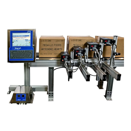
Integrated Valve Section 4: Installation Section 4: Installation System Overview The figure below illustrates a typical install, with conveyor-mounted controller and four print heads. (Cables and ink lines are not shown.) 5760-107 Operations Manual Rev C Page 15 of 86... -
Page 24: Testing The Electrical Outlet
Integrated Valve Section 4: Installation Testing the Electrical Outlet CAUTION: The outlet must be installed near the equipment and must be easily accessible. ATTENTION: On doit installer à côté de l'appareil une prise de courant facilement accessi- ble. Before installing the IJ3000 system, verify the integrity of the 115VAC sourced power, in accordance with the National Electric Code (NEC) and approved local electrical codes. -
Page 25: Installing Controller/Ids Bracketry
Integrated Valve Section 4: Installation Installing Controller/IDS Bracketry This section shows controller/IDS bracketry 4-Hole Corner Bracket Mounts to Conveyor mounted to a conveyor. This is the most common mounting method, and the most stable, as all bracketry is bolted directly to the conveyor. -
Page 26: Print Head Bracketry
Integrated Valve Section 4: Installation Print Head Bracketry This section shows bracketry for a single, conveyor-mounted print head. See Section 3, System Components , for other print head bracketry options. With all conveyor-mounted options, plant maintenance will need to drill holes in the con- veyor for final attachment. -
Page 27: Mounting The Photosensor
Integrated Valve Section 4: Installation Mounting the Photosensor 1. Position the photosensor (5760-383) upstream from the first print head. The maximum placement distance is 81 inches from the photocell to the print head. 2. The photosensor depth range can be adjusted by turning the sensitivity potentiometer on the back of the photosensor. -
Page 28: The Encoder
Integrated Valve Section 4: Installation The Encoder The encoder (5700-731) uses a wheel that rolls against the conveyor line to track the speed. It sends a signal to the controller, which makes Conveyor adjustments reported changes in the line speed. It is not necessary to install the encoder immediately adja- cent to the print heads. -
Page 29: Cpu Connections
Integrated Valve Section 4: Installation CPU Connections All controller cables must be routed through the strain relief cable clamp in the back of the controller. The controller to print head cable must be connected to the highest vertical head. Print head to print head cables should be connected from the top head Cable Clamp down as shown in the following drawing. -
Page 30: Configuring The Ids
Integrated Valve Section 4: Installation Configuring the IDS 1. Remove the IDS cover. Beacon Ethernet Power Cord 2. Install cables through their respective bulk- head fittings, leaving ¼" Ink Low Level Detect of the large cable jacket extending outside the bulkhead fitting. -
Page 31: Plumbing The System
Integrated Valve Section 4: Installation Plumbing the System All ink line connections should be as short as possible. Additional ink line can be pur- chased if necessary. The IDS may be located up to 100 feet from the print heads. When installing ink line, be sure to slide the tubing completely over the exposed barbs on the fittings to prevent ink line leaks while under pressure. - Page 32 Integrated Valve Section 4: Installation 3. Cut an ink line [D] to the desired length and connect one end to the other side of the T connector [J] . Add another T connector to this line and attach the second ink regulator and the second print head.
-
Page 33: Connecting The Ink Supply
Integrated Valve Section 4: Installation Connecting the Ink Supply Wear eye protection and use appropriate safety equipment when working with ink. 1. Place a pail of Diagraph ink within eight feet of the IDS. 2. Unscrew the shipping cap from the pail. Insert the cap assembly and tighten snugly by hand. -
Page 34: Priming The System
Integrated Valve Section 4: Installation Priming the System 1. To prime the IDS3000 for the first time after installation, hold the prime button and simulta- neously depress the Power button. The pump will Prime automatically start, and will run for up to 20 cycles, pushing ink into the lines. -
Page 35: Checking Ink Pressure
Integrated Valve Section 4: Installation Checking Ink Pressure Pressure Gauge Variations in ink pressure produce different dot sizes; the higher the pressure, the larger the dot. However, over-pressurizing a print head can result in leakage, or cause ink to shoot across the conveyor. Under- pressurizing can cause ink to drip from the front plate while printing;... -
Page 36: Setting Ink Pressure
Integrated Valve Section 4: Installation Setting Ink Pressure NOTE: The ink regulator comes preset from the factory. Check ink pressure before making any adjustments. Decreases Increases Pressure Pressure Unlock Red Locking Ring Lock 1. Close the ink regulator by pulling up on the red locking ring and turning the knob counter-clockwise until it stops. -
Page 37: Operational System Test
Integrated Valve Section 4: Installation Operational System Test After the equipment installation is complete (including all ink line and electrical connec- tions), a print head purge should be performed. Power On both the IJ3000 Controller and the IDS3000 Ink Delivery System. Prior to purging the print heads, the Print Station Config- uration needs to be set up on the IJ3000 Controller, per the following instructions. -
Page 38: Specifying Number Of Print Heads
Integrated Valve Section 4: Installation Specifying Number of Print Heads Touch the up/down arrows to set the number of print heads on each side of the conveyor. The illustration at the top of the screen will automatically change to reflect your choices. In the example at right, four print heads have been speci- fied on the near side and two on the far side of the conveyor. -
Page 39: Defining Print Head Properties
Integrated Valve Section 4: Installation Defining Print Head Properties The final step in print head configuration is defining the properties of the individual print heads. Beginning with print head number one and working in numerical order, you will need to define the following: •... -
Page 40: Purging Print Heads
Integrated Valve Section 4: Installation Purging Print Heads Purge all heads with ink as follows: 1. On the Home Screen menu, select Print. 2. On the Print menu, select Purge . 3. Touch the head you wish to purge first. 4. -
Page 41: Section 5: Frequently Asked Questions
Integrated Valve Section 5: Frequently Asked Questions Section 5: Frequently Asked Questions Q: How do I fine-tune my print so all the message lines are aligned flush left? A: Adjust the Product Sensor Offset . This is the distance in inches from the photosensor to the print head. - Page 42 Integrated Valve Section 5: Frequently Asked Questions Page 34 of 86 5760-107 Operations Manual Rev C...
-
Page 43: Section 6: Maintenance
Integrated Valve Section 6: Maintenance Section 6: Maintenance The following are the recommended maintenance procedures to keep the IJ3000 ink jet system printing cleanly and efficiently. System Maintenance Intermittent (as required): 1. Be sure the photosensor is clean and free of debris. 2. -
Page 44: Shutdowns Of Seven Days Or Longer
Integrated Valve Section 6: Maintenance Shutdowns of Seven Days or Longer Flush and thoroughly purge the print head and the IDS3000. After extended shutdown periods of a week or longer, it may be necessary to flush all print heads with Diagraph Ink Jet Conditioner, as follows: 1. -
Page 45: Ids Maintenance
Integrated Valve Section 6: Maintenance IDS Maintenance Changing Ink Containers CAUTION: Porous ink must be used with a porous IDS. Non-porous ink must be used with a non-porous IDS. The IDS can not be flushed to use a different ink type. The Ink-Out Beacon lights when the ink pail is almost empty. -
Page 46: Daily Startup
Integrated Valve Section 6: Maintenance The following procedure explains how to change ink while the system continues to print. Determine whether the system is using porous (TWP) or non-porous (TSO) ink, and replace with the same type of ink. Changing ink colors is a two step process: first flush the system with the appropriate condi- tioner for your ink type, then change ink colors - making sure to use the same ink type. -
Page 47: Section 7: Troubleshooting
Integrated Valve Section 7: Troubleshooting Section 7: Troubleshooting The IJ3000 ink jet system incorporates advanced designs, both in hardware and in soft- ware. However, if the system ever fails to perform properly, some built-in indicators will help in troubleshooting. This section will help minimize system downtime and explain some of the diagnostic features built into the system. -
Page 48: Photosensor Test
Integrated Valve Section 7: Troubleshooting Photosensor Test This test will determine if the photosensor is functioning correctly for the application. 1. Place the product in front of the photosensor as in normal operation. 2. The LED on the rear of the photosensor should illuminate. 3. -
Page 49: Encoder Functional Testing
Integrated Valve Section 7: Troubleshooting Encoder Functional Testing In the event of print quality problems that point to variations in encoder performance or location with an IJ3000 Ink Jet System, this procedure will help to verify proper encoder function. Tools: •... - Page 50 Integrated Valve Section 7: Troubleshooting When you're satisfied that the encoder is tracking normally, you can calculate the encoder frequency as follows: Measure the time from the leading edge of one of the 5-volt square waves to the leading edge of the one next to it. Divide 1 by the time you measured.
-
Page 51: Print Quality Troubleshooting
Integrated Valve Section 7: Troubleshooting Print Quality Troubleshooting Diagnosis HOW TO USE THIS SECTION: 1. Look at the problem characters on your substrate and compare them with the figure below to diagnose the exact name for the problem. 2. Look at the next segment entitled "Print Quality Definitions" to verify that you classified the problem correctly. - Page 52 Integrated Valve Section 7: Troubleshooting Print Quality Definitions The system prints dots that are different in size. [1] Internal Dot Size Variation [2] Extra Dots The system continues to print dots outside the designated dot columns. [3] Tails The system prints dots with small trails of ink. [4] Splatter The system prints shapeless dots surrounded by tiny "aerosol"...
- Page 53 Integrated Valve Section 7: Troubleshooting PRINT QUALITY POSSIBLE CAUSE PROBLEM Internal Dot Size Variation • Low ink pressure Extra Dots • High ink pressure • Pulse width set too high • Incorrect pre-load Tails • Print head too far from the target •...
-
Page 54: Setting Ink Pressure
Integrated Valve Section 7: Troubleshooting Setting Ink Pressure Ink pressure must be set within specifications using an ink pressure gauge. Lowering the ink pressure to alleviate print head seepage may result in performance and reliability problems. The I.V. design relies on the equilibrium of ink pressure, pre-load, and pulse width. -
Page 55: Ink Regulator Maintenance Procedure
Integrated Valve Section 7: Troubleshooting Ink Regulator Maintenance Procedure If print dot size is fluctuating , check the print head pressure. If the dot size fluctuations can be correlated to changes in ink pressure, the ink regulator may be in need of service. Dot diameters will decrease if the regulator input pressure is less than 2.0 PSIG greater than the print head pressure (6 PSIG). -
Page 56: Print Head Pulse Width Adjustment
Integrated Valve Section 7: Troubleshooting Print Head Pulse Width Adjustment When a print head solenoid is on, the piston pulls away from the membrane, ink pressure moves the membrane away from the orifice, and ink is expelled through the orifice to form a dot. -
Page 57: Cleaning The Front Plate Of A Clogged Print Head
Integrated Valve Section 7: Troubleshooting Cleaning the Front Plate of a Clogged Print Head If dots are missing from the print, the print head front plate may have dried ink or debris covering the orifices. To clean the front plate: 1. -
Page 58: Print Head Pre-Load Adjustment
Integrated Valve Section 7: Troubleshooting Print Head Pre-Load Adjustment Pre-load adjustment is sometimes required, as print head components wear over time. Pre-load adjustment may be required under the following conditions: • Excessive or constant ink leakage . • Poor print quality in the form of tails, extra dots, splattering , or a stuck open valve. •... - Page 59 Integrated Valve Section 7: Troubleshooting 5. Locate the row of bushings inside the 5/16 5.0 print head. A label inside the print head 7/8 6.0 cover indicates the bushings (sole- noids) and their corresponding print ori- fices. 6. Rotate the bushing counter-clockwise SOLENOID LOCATION ORIFICE LOCATION with the solenoid adjustment tool until...
- Page 60 Integrated Valve Section 7: Troubleshooting Page 52 of 86 5760-107 Operations Manual Rev C...
-
Page 61: Appendix A: System Specifications
Integrated Valve Appendix A: System Specifications Appendix A: System Specifications Ink Delivery System Size Height: 5.7" (144mm) Width: 12.0" (304.8mm) Depth: 10.0" (255mm) Weight: 14 lb. (6.4kg) Cable Clearance: 3" from the rear of the 10.0” TOP VIEW [255mm] Enclosure Cold rolled steel (painted black) or stain- less steel Ink Filtration... - Page 62 Integrated Valve Appendix A: System Specifications Page 54 of 86 5760-107 Operations Manual Rev C...
-
Page 63: Appendix B: Theory Of Operation
Integrated Valve Appendix B: Theory of Operation Appendix B: Theory of Operation Functional Description The IJ3000 ink jet system prints text, autocodes (such as product counts or time and date stamps) and/or graphics onto products as they travel by conveyor past stationary print heads. -
Page 64: Encoder
Integrated Valve Appendix B: Theory of Operation Encoder The encoder determines the time period between the printing of individual columns, or the print speed. As a product's speed increases, the time period between columns must decrease, that is, the print speed must increase, to maintain consistent column-to-column spacing. -
Page 65: Cpu Board
Integrated Valve Appendix B: Theory of Operation CPU Board The CPU Board has two microcontrollers, an LCD controller, flash memory, SRAM, a real time clock/calendar, an Ethernet port, two serial ports, 12V, 5V and 3.3V regulators, a 3V battery, and PC/104 bus connectors. Of the two microcontrollers, one (U13) is the IJ3000's central processing unit (CPU). -
Page 66: I.v. Print Head Interface Board
Integrated Valve Appendix B: Theory of Operation I.V. Print Head Interface Board The I.V. Print Head Interface Board controls the print head daisy chain, and it is the power entry point for the print heads and the rest of the system (See the Power section above.) The Print Head Interface Board also contains the photosensor and external encoder con- nectors. -
Page 67: Ink Delivery System Features
Integrated Valve Appendix B: Theory of Operation Ink Delivery System Features The Ink Delivery System (IDS) provides ink to the print heads. In addition to pumping ink from the supply container, the IDS is programmed with the following features: 1. Continuous monitoring and maintenance of ink line pressure. Whenever the pressure drops to a level of 20 psi, the IDS pump turns on for five seconds and the pressure returns to a level between 23 and 27 psi. -
Page 68: Ink Low Detection
Integrated Valve Appendix B: Theory of Operation PRESSURE SENSOR CKECK VALVE LOGIC BOARD TO ACCUMULATOR ACCUMULATOR PUMP PRIME SWITCH THERMAL ON/OFF SWITCH CUT-OFF REPRESENTS INK FLOW Ink Low Detection At a point prior to supply depletion, the low level detect sensor sends a closed signal back to the IDS3000. -
Page 69: Print Head Broken Line Detection
Integrated Valve Appendix B: Theory of Operation Print Head Broken Line Detection Because accidents are possible in any factory environment, the IDS3000 provides protec- tion against continuous dumping of fluid from the ink supply after an "open" has been cre- ated in the print head supply line. -
Page 70: Ids Board Test Points
Integrated Valve Appendix B: Theory of Operation IDS Board Test Points LED2 LED1 IDS BOARD TP11 GREEN LED3 TP13 LED4 YELLOW TP12 TRANS PUMP Test Points: TP1, TP2: (TP1 - TP2) = 8mV/PSI at the vacuum sensor (applies only to IDS3000 Assembly, Revisions A - F) TP3: 0.2V/PSI of vacuum (applies only to IDS3000 Assembly, Revisions A - F) -
Page 71: Ids Wiring Diagrams
Integrated Valve Appendix B: Theory of Operation IDS Wiring Diagrams 5760-107 Operations Manual Rev C Page 63 of 86... - Page 72 Integrated Valve Appendix B: Theory of Operation Page 64 of 86 5760-107 Operations Manual Rev C...
-
Page 73: Appendix C: Parts And Supplies
Integrated Valve Appendix C: Parts and Supplies Appendix C: Parts and Supplies Consumables The following is a partial list of inks offered by Diagraph. Your sales representative can advise you on the proper ink for your application. Porous Inks Description Type Available Colors TWP-101... -
Page 74: Parts In Modular Kits
Integrated Valve Appendix C: Parts and Supplies Parts in Modular Kits Part # Description Contents 1902-964 Flush Bottle Kit 1902-857 Print Head Broach Kit 5700-743 Pressure Gauge 5701-501 Ink Regulator Kit (Non-Porous) 1 regulator, 1 bracket assembly 5701-502 Ink Regulator Kit (Porous) 1 regulator, 1 bracket assembly 5750-503... -
Page 75: Ids Assembly Kits
Integrated Valve Appendix C: Parts and Supplies IDS Assembly Kits ITEM PART NO. DESCRIPTION 5760-311 PCB REPLACEMENT KIT 5760-314 TRANSFORMER REPLACEMENT KIT 5760-315 PUMP REPLACEMENT KIT, 115VAC 5760-318 PUMP REPLACEMENT KIT, 230VAC 5760-317 INTERNAL TUBING AND FITTINGS KIT 5760-389 THERMAL CUTOFF KIT 5760-394 ACCUMULATOR REPLACEMENT KIT 5760-107 Operations Manual Rev C... - Page 76 Integrated Valve Appendix C: Parts and Supplies Page 68 of 86 5760-107 Operations Manual Rev C...
-
Page 77: Appendix D: Maximum Dpi Calculation For A Given Line Speed
Integrated Valve Appendix D: Maximum dpi Calculation for a Given Line Appendix D: Maximum dpi Calculation for a Given Line Speed The maximum line speed of an I.V. print head is limited by the maximum frequency of the solenoid, which is 1000 Hz. The following steps will determine the operating frequency of the solenoids in the application. - Page 78 Integrated Valve Appendix D: Maximum dpi Calculation for a Given Line Page 70 of 86 5760-107 Operations Manual Rev C...
-
Page 79: Appendix G: Font Samples
Integrated Valve Appendix E: Font Samples Appendix E: Font Samples Character appearance is affected by weight and dots per inch (dpi). Character weights available are single dot and bold (double dot). The term "fixed" means the space allotted per character is the same regardless of the character. (An "I" occupies the same space as a "W".) PRINT SAMPLES FOR A ½"... - Page 80 Integrated Valve Appendix E: Font Samples 9-dot (single dot) 12.5 9-dot bold (double dot) fixed 12.5 PRINT SAMPLES FOR A 1" 18-DOT PRINT HEAD 18-dot bold (double dot) Page 72 of 86 5760-107 Operations Manual Rev C...
- Page 81 Integrated Valve Appendix E: Font Samples 3 x 5-dot (single dot) 16.67 9-dot (single dot), 9-dot bold (double dot) 16.67 5-dot (single dot), 9-dot (single dot) 16.67 5760-107 Operations Manual Rev C Page 73 of 86...
- Page 82 Integrated Valve Appendix E: Font Samples PRINT SAMPLES FOR A 7/8" 9-DOT PRINT HEAD (CAN ALSO BE PRINTED WITH A 2" 18-DOT PRINT HEAD) 5-dot (single dot) 12.5 16.67 7-dot (single dot) fixed 12.5 Page 74 of 86 5760-107 Operations Manual Rev C...
- Page 83 Integrated Valve Appendix E: Font Samples 7-dot bold (double dot) 12.5 9-dot (single dot) 12.5 5760-107 Operations Manual Rev C Page 75 of 86...
- Page 84 Integrated Valve Appendix E: Font Samples 9-dot bold (double dot) 12.5 PRINT SAMPLES FOR A 2" 18-DOT PRINT HEAD 18-dot bold (double dot) Page 76 of 86 5760-107 Operations Manual Rev C...
- Page 85 Integrated Valve Appendix E: Font Samples 18-dot bold (double dot) 16.67 9-dot (single dot), 9-dot bold (double dot) 16.67 5760-107 Operations Manual Rev C Page 77 of 86...
- Page 86 Integrated Valve Appendix E: Font Samples 5-dot (single dot), 9-dot (single dot) 16.67 Page 78 of 86 5760-107 Operations Manual Rev C...
-
Page 87: Appendix F: Setting The Ip Address Of An Ids3000
Integrated Valve Appendix F: Setting the IP Address of an IDS3000 Appendix F: Setting the IP Address of an IDS3000 Equipment Needed • IDS3000 • PC with an Ethernet port • Ethernet crossover cable (Diagraph part number 5760-240, shipped with the IDS3000) •... - Page 88 Integrated Valve Appendix F: Setting the IP Address of an IDS3000 5. Plug one end of the Ethernet crossover cable into P1 on the circuit board. Plug the other end into the Ethernet connector on your PC. 6. Plug in the IDS3000 and turn it on. 7.
-
Page 89: Appendix G: Testing An Electrical Outlet
Integrated Valve Appendix G: Testing an Electrical Outlet Appendix G: Testing an Electrical Outlet An outlet tester is the preferred method of checking an electrical outlet, although a voltme- ter can also be used. 115VAC 115VAC 115VAC 115VAC 115VAC 115VAC CORRECTLY WIRED INCORRECTLY WIRED INCORRECTLY WIRED... - Page 90 Integrated Valve Appendix G: Testing an Electrical Outlet Page 82 of 86 5760-107 Operations Manual Rev C...
-
Page 91: Appendix H: Electrostatic Discharge (Esd)
Integrated Valve Appendix H: Electrostatic Discharge (ESD) Appendix H: Electrostatic Discharge (ESD) What is ESD? Electrostatic Discharge (ESD) is a triboelectric charge generated by separating or rubbing together two non-conductive materials. What causes ESD? Friction can cause ESD. Friction can be generated by walking across a floor, removing tape from a tape dispenser, pulling a work order from a plastic work order holder, rolling the wheels of a push-cart across the floor, sitting on a foam cushion such as a stool or blowing air across a nonconductive surface. - Page 92 Integrated Valve Appendix H: Electrostatic Discharge (ESD) Page 84 of 86 5760-107 Operations Manual Rev C...
-
Page 93: Appendix I: Glossary Of Terms
Integrated Valve Appendix I: Glossary of Terms Appendix I: Glossary of Terms Accumulator - Housed within the IDS, the Font - A complete set of characters - accumulator stores ink for delivery to the alphabetic, numeric, and punctuation - in print heads. - Page 94 Integrated Valve Appendix I: Glossary of Terms Print Indentation -The sum of two mea- Printstation - One or more print heads set surements: The distance from the photo- up to mark a given product in a specified sensor to the center of the print head, plus location.
Need help?
Do you have a question about the Diagraph IJ3000 and is the answer not in the manual?
Questions and answers