Table of Contents
Advertisement
Quick Links
Advertisement
Table of Contents

Subscribe to Our Youtube Channel
Related Manuals for ITW SIMCO ION Manager IQ Easy


Summary of Contents for ITW SIMCO ION Manager IQ Easy
- Page 1 SIMCO (Nederland) B.V. Postbus 71 NL-7240 AB Lochem, The Netherlands Telephone +31 (0)573-288333 +31 (0)573-257319 Email general@simco-ion.nl Internet http://www.simco-ion.nl Trade Register Apeldoorn No. 08046136 Manager IQ Easy Control unit ManagerIQEasy_UM_9752103002_GB_V3_1...
-
Page 2: Table Of Contents
CONTENTS Preface ............................... 4 Explanation of symbols ........................4 1 Introduction ............................. 5 2 Description and operation ........................ 6 3 Safety .............................. 8 4 Technical specifications ........................9 5 Systems ............................11 5.1 Checks ..............................11 5.2 General ..............................11 5.3 Fitting the Manager IQ Easy........................ - Page 3 6.12 Changing a parameter ........................43 6.13 Overview of HMI parameters ......................48 6.14 Overview of Backplane / ExtensionBox parameters................51 6.15 Overview of common Device parameters .................... 54 6.16 Switching off the Manager IQ Easy ...................... 56 6.17 Changing some commonly used parameters ..................58 6.17.1 Setting the user language of the HMI (Expert user) ....................
- Page 4 6.27.2 Searching manually for Extension IQ Easy units....................112 6.28 Disconnecting a Device (Expert user) ....................113 6.28.1 Device disconnected notification.......................... 113 6.28.2 Restoring a disconnected Device........................... 114 6.28.3 Removing the Disconnected Device from the IQ Easy system................115 6.29 Replacing a defective Device (Expert user) ..................
-
Page 5: Preface
Preface This manual is intended for the installation and use of the MANAGER IQ EASY. This manual describes the installation and basic menus of the Manager itself. The different possibilities of the connected equipment using the Manager is described in detail in the manual of the relevant Device. -
Page 6: Introduction
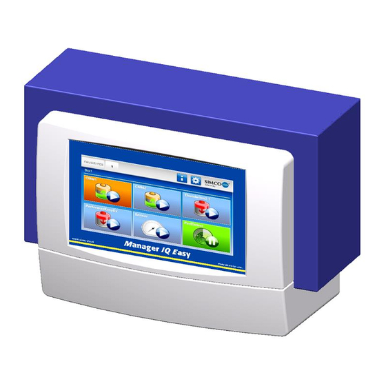
1 Introduction The Manager IQ Easy is equipped with an on/off switch, 6 connectors for connecting Simco-Ion equipment (Devices), various I/O connectors and a 7” touchscreen as a user interface. The user interface is in colour and can be easily operated using a finger or stylus. Using the Manager IQ Easy, Simco-Ion equipment can be configured, read out, monitored and controlled. -
Page 7: Description And Operation
2 Description and operation After starting the Manager IQ Easy, it will display the status of the connected equipment on the main screen. Six possible Devices are displayed on the main screen. The operating status of each Device can be read directly through the colours and icons used. If you require more information regarding a specific Device, you can retrieve this information by pressing the appropriate icon. - Page 8 On each tab, you can set the Device to standby or active mode. Specific information of each tab is described in the manual of the corresponding Device. ManagerIQEasy_UM_9752103002_GB_V3_1...
-
Page 9: Safety
3 Safety The following safety guidelines must be observed in order to prevent physical injury and damage to objects or the Manager IQ Easy itself. Warning: Electrical installation must be carried out by a qualified electrician in accordance with national and local regulations. The Manager IQ Easy must not be used in any environment where there are fire or explosion hazards. -
Page 10: Technical Specifications
4 Technical specifications 100 – 240V AC nom. (90 – 305V AC) Supply voltage 24V DC - 3/+10% 50 – 60Hz nom. (47 – 63Hz) Frequency 300W (100 – 240V AC version) Max power consumption 360W ( 15A) (24V DC version) Purpose Industrial, indoor use Protection class... - Page 11 Figure 3, Drilling template Manager IQ Easy and Extension IQ Easy ManagerIQEasy_UM_9752103002_GB_V3_1...
-
Page 12: Systems
5 Systems Warning: - The electrical installation must be carried out by an electrical engineer with the relevant training and qualifications. Disconnect the power supply before carrying out any work on the unit. - Consult the manuals of the Device to be connected for proper and safe connecting and use of the Device. -
Page 13: Electrical Installation
Mounting on a flat surface: - Remove the plastic bottom cover of the Manager by bending the side flaps slightly outward and sliding the cover up. - Use the supplied drilling templates to mark the mounting holes. Make sure that there is sufficient space at the bottom for installing the cables. -
Page 14: Ac Variant
5.4.1 AC variant - Plug the power cable into the IEC connector and plug the outlet plug into an earthed wall outlet. 5.4.2 24V DC variant – Connect the 24 V DC power connector as shown in figure 5. – Connect the earthing (ground) point with an earthed machine part or a shared earthing point. Figure 5, 24 V-input Manager IQ Easy 5.4.3 Connecting Devices Six M12 Device ports are available for connecting various Simco-Ion Devices. -
Page 15: Machine I/O Input And Output Connections
5.4.4 Machine I/O Input and output connections The Manager IQ Easy has a 25-pin Sub D connector where various in- and output signals are available. These can easily be connected to a machine controller or PLC, making it possible to transmit warnings and alarms to the machine. -
Page 16: Remote On/Off Input
5.4.4.2 Remote on/off input Each connected Device can be switched via the remote on/off input. How to connect the Device with this input is explained in the manual of the corresponding Device (see the “Remote on/off source” parameter, Section 6.6). Connect an external 24 V switching signal between pins 24 and 25 (24V = Remote ON, 0V = Remote OFF) Or: Use the 24V DC output and connect a potential-free switching contact between pins... -
Page 17: Serial Communication Com Ports
5.4.7 Serial communication COM ports For expanding the system with more than 60 Devices, two COM ports are available to which extension IQs can be connected. Standard cables with M8 3-pin male-female connectors can be used for this. These are available from Simco-Ion 5.4.8 Installing the protective cover When all cables are connected, the cable protection cover can be mounted. - Page 18 The plastic front of the Manager IQ Easy is attached to the housing by means of 4 snap connectors. Carefully pull away the plastic front from the housing. The plastic part can be loosened using a larger flat screwdriver. There are two recesses below the plastic part for this. Note: Do not pull on the wiring between the front and the housing.
- Page 19 Place the housing behind the machine panel and secure it with the 4 tap bolts and washers (1). Make sure that the wires are not squeezed between the housing and the machine panel. Screw the four snap connectors into the housing through the machine panel. ManagerIQEasy_UM_9752103002_GB_V3_1...
- Page 20 Mount the wiring connectors from the housing back onto the front. Click the front onto the four snap connectors on the machine panel. ManagerIQEasy_UM_9752103002_GB_V3_1...
- Page 21 ManagerIQEasy_UM_9752103002_GB_V3_1...
-
Page 22: Commissioningand Operation
6 Commissioning and operation Figure 10, removing the protection film from the display - First, carefully remove the protection film from the touchscreen. Switching on - Make sure that supply voltage is available in the power cable. - Switch the Manager on using the power switch. Note: - The Manager is suitable for continuous operation. -
Page 23: Terminology Used
6.1 Terminology used Manager IQ Easy A box consisting of an HMI and a Backplane IQ Easy. Six Devices can be connected to this box and with the help of Extension IQ Easy units it can be expanded to a maximum of 30 Devices. The Manager IQ Easy is used to control the entire system using a touchscreen display. -
Page 24: Switching On The Manager Iq Easy
6.2 Switching on the Manager IQ Easy After switching on the Manager IQ Easy, it will start automatically. During the start-up of the IQ Easy System, a check will be made whether a software update can be performed. An FTP server and the Manager IQ Easy software will also be started. -
Page 25: The Main Screen
6.3 The main screen The main screen of the Manager IQ Easy looks like this: In the main screen ( ) of the Manager IQ Easy you can find different icons and buttons. The icons indicate a status, while the buttons are used to operate the Manager IQ Easy. Below is an overview of the available icons and buttons in the main screen and the corresponding meaning or functionality. - Page 26 (Info) button can also be shown as (Busy). At that time, the HMI is busy with a background task, such as reading in the parameters of the Backplane, an Extension IQ Easy or a Device. It can also mean that files are being copied to a USB stick, for example if a copy of all log files of the system is made.
-
Page 27: Devices
6.4 Devices The Manager IQ Easy system basically has 4 different types of Device groups. A unique icon is used for each Device group. This makes it easy for the user to recognise what kind of Device it is. The following icons are used for this purpose: Symbol Description Device type The Device is not connected. -
Page 28: Operating Modes
6.5 Operating modes 6.5.1 Standby and Run The Manager IQ Easy system has two basic operating modes. Either a Device is active and can emit high voltage, or a Device is not active and cannot emit high voltage. The active state is called ‘Running’, the inactive state ‘Standby’. -
Page 29: Remote On/Off
6.6 Remote on/off The IQ Easy system has the possibility to switch Devices on and off via an external control. Two remote controls are available for this: via the Remote I/O connector or via an optional (Fieldbus) interface. By using the Remote I/O control, Devices can be switched ‘on’ and ‘off’ faster and at the same time. -
Page 30: Status Information
6.7 Status information The background colours indicate the status of the connected Devices. This status depends on the parameter “Run state display colour green”. Adjusting the parameter “Run state display colour green” is described in Section 6.17.10. “Run state display colour green” Status value Inactive or no communication... - Page 31 The status of the Remote I/O control is displayed with the help of icons. Remote icon Definition The Device has no Remote I/O control (Continuous mode). The Device is active with Remote I/O, but the Remote I/O control is OFF. The Device is active with Remote I/O, the Remote I/O control is ON.
-
Page 32: Userlevels
6.8 Userlevels The IQ Easy system has 4 different (User levels). The (Basic) level will be active when the system is switched on. At this level the basic functionality of the Manager IQ Easy will be available and the user cannot change any parameters and settings. By activating a higher user level, more parameters and settings become visible and more parameters and settings can also be adjusted. -
Page 33: Selecting A Different (Userlevel)
6.9 Selecting a different (Userlevel) To activate another user level, perform the following actions. If necessary, go to the main screen (Home). Press (Userlevel). The following screen will open. Select the desired user level (e.g. “Basic”, “Advanced”, “Expert” or “Service”). ManagerIQEasy_UM_9752103002_GB_V3_1... - Page 34 Note: - Before the “Advanced”, “Expert” and “Service” user levels, a new screen may appear that requires entering a password or special access code. Then enter the password or access code and press (Accept). After selecting the new user level (and possibly entering a password or a special access code), the Manager IQ Easy will return to the main screen.
-
Page 35: Special Service Access Codes
6.10 Special Service access codes The following special access codes are available: Access Code Definition 2257 All parameters and settings available for the system or Device will be displayed. This code is also used to copy the Debug files needed for Simco when copying the log files to a USB stick. -
Page 36: Device Information Screens
6.11 Device information screens 6.11.1 Tab “Information” (Information) / “Settings” (Settings) In the Information (Information) / Settings (Settings) tab, the available parameters and settings of the Device are displayed. Note: - If an “Undefined param” appears on the info screen of a Device on the Manager, the Manager must be updated with the latest software. - Page 37 Click (Stand-by) to put a single Device or the whole system (all Devices) in Standby mode. Click (Run) to set a single Device or the whole system (all Devices) to Run mode Parameter screen Button Button Put all Devices in Standby. Put all Devices whose parameter “Autorun”...
- Page 38 Press the button indicated by the left arrow to go to the previous page. Press the button indicated by the right arrow to go to the next page. In the parameter screen of the Devices, an additional icon is included, which shows the operating mode and status of the Device.
-
Page 39: Tab "Graphics
6.11.2 Tab “Graphics” The “Graphics” screen graphically displays the operation of the Device. The graph shows important measured values in relation to time, in the case of a Sensor, the current measured values. In the key it is made clear what the representation of each coloured line is. Press (Graphics) to display the graphical display. -
Page 40: Tab "Actionlog
6.11.3 Tab “ActionLog” The “ActionLog”saved tab stores the different actions step by step, such as whether the Device is in Running mode or Standby mode, whether the Remote input is active or not, and whether high voltage is output. In the event of any warnings or alarms, it is also indicated here what is going on. -
Page 41: Tab "Datalog
6.11.4 Tab “DataLog” The “DataLog” tab is used to store the measurement values that are important for the Device at a fixed time interval. The last 10 registrations can be found in this screen. The saved measured values can also be found in a log file of the Device. Press (DataLog). -
Page 42: Tab "Maintenance
6.11.5 Tab “Maintenance” The “Maintenance” tab allows you to perform maintenance instructions on the IQ Easy System or a Device. For example, a Performax IQ Easy bar can be recalibrated if this bar displays the warning “Calibrate bar”. Pressing the Action button located behind the Action “Calibrate bar”... - Page 43 Save configuration (HMI only) Save the current configuration of the system so that it can be checked whether it is still valid. See also parameter “Check last configuration”. Clear system alarm (HMI only) Use this Action to clear a System Configuration Alarm. See also parameter “Check last configuration”.
-
Page 44: Changing A Parameter
6.12 Changing a parameter To go to the HMI, Backplane, Extension IQ Easy or Device parameter screen, do the following: Press (Info). Backplane Press (TabM) and press (Info) within 1 second. Extension IQ Easy Press the relevant tab: (Tab1), (Tab2), (Tab3) or (Tab4), and press the (Info) button within 1 second. - Page 45 Press the of the relevant parameter to be able to change the setting. In the example we are going to change the name of the HMI. Press the to the right of the parameter “Device name”. ManagerIQEasy_UM_9752103002_GB_V3_1...
- Page 46 A new screen will open depending on the type of parameter. For this parameter it will be a keyboard with which the name can be entered. Now enter the desired name (e.g. “System Manager1”). The following special keys are available: ManagerIQEasy_UM_9752103002_GB_V3_1...
- Page 47 Press (Backspace) to delete the last character. Press (Clear) to delete everything. Press (Space) to enter a space. Press (Upper) to switch to capital letters and special characters. Press (Lower) to switch to lower case and the numeric keys. Press (Show) to make the password visible.
- Page 48 Click (Home) to return to the main screen. Depending on the type of parameter, a different input screen will appear. Some common screens are: In the screen the current value of the parameter is indicated by a (Select). Press one of the other possible settings to change the parameter and return to the parameter screen.
-
Page 49: Overview Of Hmi Parameters
6.13 Overview of HMI parameters The HMI has the following parameters and settings (Depending on the selected user level, more or fewer parameters and settings may be visible). Parameter name Values Description Device name HMI name to be entered by the user. This allows the HMI to be given a name that is recognisable to all users. - Page 50 Ethernet IP address 0.0.0.0 Display of the IP address assigned to the Manager IQ Easy. The FTP server can be used via this IP address to access the log files of the Manager IQ Easy via the network. Buzzer Touching the screen surfaces does not produce an acoustic signal.
- Page 51 Popup on disconnected If communication with an Extension IQ Easy is ExtBox lost, no pop-up will be displayed. If communication with an Extension IQ Easy is lost, a pop-up will be displayed with this warning. Popup on disconnected If communication with a Device is lost, no pop-up Device will be displayed.
-
Page 52: Overview Of Backplane / Extensionbox Parameters
6.14 Overview of Backplane / ExtensionBox parameters The Backplane and Extension IQ Easy units have the following parameters and settings (Depending on the selected user level, more or fewer parameters and settings may be visible). Parameter name Values Description Device name Name of the Backplane or Extension IQ Easy entered by the user. - Page 53 Fieldbus BusError (*) 0x00 Error code if there are problems with the Fieldbus module or the network. The code 0x00 indicates that there is no error or fault; every other value indicates that a problem was found during the initialisation of the Fieldbus module. Contact your Simco-Ion to solve this problem.
- Page 54 The signals on the Device communication port Toggle RS485 AB are not switched. The signals on the Device communication port are switched. Enable this parameter if older Performax IQ and/or Sensors are used in the system. The parameter can also be switched on if a mistake is made during the wiring, as a result of which Devices are not detected by the HMI.
-
Page 55: Overview Of Common Device Parameters
6.15 Overview of common Device parameters Some common parameters will be described here. The specific parameters of the different Devices will be described in the manuals of the Devices. Parameter name Values Description Device name Device name to be entered by the user. This is to give the Device a name that is recognisable to all users. - Page 56 Last warning Date and timestamp indicating when the last Warning was registered. Last alarm Date and timestamp indicating when the last Alarm was registered. Data logging The data logging (measured values) for the Device is disabled. The data logging (measured values) for the Device is enabled.
-
Page 57: Switching Off The Manager Iq Easy
6.16 Switching off the Manager IQ Easy If necessary, go to the main screen (Home). Press (Userlevel). The following screen will open. Press “Save data & shutdown”. A blue screen appears with the text “IQ EASY IS READY TO SHUTDOWN”. ManagerIQEasy_UM_9752103002_GB_V3_1... - Page 58 Now turn off the Manager IQ Easy by turning off the mains power button. Note: - Uncontrolled or incorrect switching off of the Manager IQ Easy can lead to corrupt data files and/or a corrupt file system. As a result, the Manager IQ Easy will start to function unreliably or will no longer log any information.
-
Page 59: Changing Some Commonly Used Parameters
6.17 Changing some commonly used parameters In the following section, some frequently used parameters will be adjusted based on examples. A few more difficult to understand parameters or settings will also be explained. 6.17.1 Setting the user language of the HMI (Expert user) To set the language of the HMI, the user must be logged in as Expert (see Section 6.8). -
Page 60: Setting The System Time (Expert User)
6.17.2 Setting the system time (Expert user) To set the clock of the HMI, the user must be logged in as Expert (see Section 6.8). If necessary, go to the main screen (Home). If necessary, log in as (User level, Expert), see Section 6.9. Press (Info). -
Page 61: Setting The Date Display ((Expert User))
6.17.3 Setting the date display ((Expert user)) The date can be displayed on the screen in different ways (Dutch, American and German formats). To adjust this setting, the user must be logged in as Expert (see Section 6.8). If necessary, go to the main screen (Home). -
Page 62: Setting A Password For The 'Advanced User' User Level
6.17.4 Setting a password for the ‘Advanced user’ user level If necessary, go to the main screen (Home). If necessary, log in as (Userlevel, Advanced/Expert), see Section 6.9. Press (Info). The (Information) screen of the HMI will now open. buttons to the page with parameter “Advanced password” Browse using the (You can also use the large non-visible areas to browse). -
Page 63: Setting A Password For The 'Expert User' User Level
6.17.5 Setting a password for the ‘Expert user’ user level If necessary, go to the main screen (Home). If necessary, log in as (User level, Expert), see Section 6.9. Press (Info). The (Information) screen of the HMI will now open. buttons to the page with parameter “Expert password”... -
Page 64: Resetting The Advanced User Password (Expert User)
6.17.6 Resetting the Advanced user password (Expert user) To change the Advanced user password, a higher user level (Expert or higher) must be logged in. If necessary, go to the main screen (Home). If necessary, log in as (User level, Expert), see Section 6.9. Press (Info). -
Page 65: Resetting The Expert User Password (Expert User)
6.17.6 Resetting the Expert user password (Expert user) To change the Expert user password, you must log in with a special Service code. If necessary, go to the main screen (Home). Press (User Level). Select “Service”. A keyboard will now appear. Enter the code “288333”. -
Page 66: Users Standby/Run Control Level (Expert User)
6.17.8 Users Standby/Run control level (Expert user) The IQ Easy Manager has the option to block (Basic users) and/or (Advanced users) from putting Devices in Standby/Running mode. The level of users who can put Devices in Standby/Running mode is set as follows (the user must log in as an Expert user, see Section 6.8). If necessary, go to the main screen (Home). -
Page 67: Setting Logging Of Sensor Peak Values (Expert User)
6.17.9 Setting Logging of Sensor Peak values (Expert user) There are 2 ways in which the measured peak measurement values of a Sensor Device can be stored in the log file. By default, this will be saved using a fixed time interval. However, it is also possible to choose to have these measured values stored on a Remote On →... -
Page 68: Setting The Run State Display Colour Green (Expert User)
6.17.10 Setting the Run state display colour green (Expert user) As explained in Section 6.5.1 and 6.7, the Manager IQ Easy has 2 modes on which the Standby and Running status colours can be displayed. If necessary, go to the main screen (Home). -
Page 69: Reading Network Ip Address (Expert User)
6.17.11 Reading network IP address (Expert user) To connect to the FTP server via a network, the user must know which IP address the Manager IQ Easy has been assigned. This IP address can be read as follows. (The user must be logged in as an Expert user, see Section 6.8) If necessary, go to the main screen (Home). -
Page 70: Linking And Disconnecting Devices (Expert User)
6.18 Linking and disconnecting Devices (Expert user) The IQ Easy system has the option to connect bars and sensors. This allows them to exchange measurement and control data with each other, so that a control loop can be built in order to suppress static electricity in a controlled manner. - Page 71 If necessary, browse using the buttons to the page with the Sensor Device to which the bar is to be linked. Now press the button for the Sensor Device to be paired. The selection screen will close and the parameter and settings screen will be displayed with the adjustment made.
-
Page 72: Linking A Sensor Device To A Bar (Expert User)
6.18.2 Linking a Sensor Device to a bar (Expert user) To link 2 or more Devices together, you must at least be logged in as an Expert user (see Section 6.8). If necessary, go to the main screen (Home). If necessary, log in as (User level, Expert), see Section 6.9. - Page 73 The following screen will be opened. If necessary, browse using the buttons to the page with the Device to which the sensor is to be linked. Now press the button for Device to be paired. The screen will close and the screen will now show the linked Device in the list. ManagerIQEasy_UM_9752103002_GB_V3_1...
- Page 74 Depending on the software version, only 1 Sensor Device can be link with 1 bar; with other software versions, linking up to 4 bars is supported. Repeat the steps described above to link or next Device to the Sensor Device. Press (Accept) to complete the pairing of the Devices and to save the created pairings.
-
Page 75: Activating The Clfb Voltage Control (Expert User)
6.18.3 Activating the CLFB voltage control (Expert user) If the Sensor Devices and Bar Devices are linked to each other, the CLFB control can be activated. For this, the user must be logged in as an Expert (see Section 6.8). If necessary, go to the main screen (Home). - Page 76 The screen will close and the CLFB control has been established. Press (Home) to return to the main screen and log in again as a Basic user (see Section 6.9). ManagerIQEasy_UM_9752103002_GB_V3_1...
-
Page 77: Disconnecting A Coupled Bar From The Sensor Device (Expert User)
6.18.4 Disconnecting a coupled bar from the Sensor Device (Expert user) To be able to disconnect linked Devices, you must at least become an Expert user (see Section 6.8). If necessary, go to the main screen (Home). If necessary, log in as (User level, Expert), see Section 6.9. - Page 78 The selection screen will close and the parameter and settings screen will be displayed with the adjustment made. Press (Home) to return to the main screen and log in again as a Basic user (see Section 6.9). Note: - The Manager IQ Easy will attempt to automatically break off the unpairing of the Sensor Devices. It is good to check in the Sensor Devices whether this has actually been achieved.
-
Page 79: Disconnecting A Sensor Device From A Bar (Expert User)
6.18.5 Disconnecting a Sensor Device from a bar (Expert user) To be able to disconnect linked Devices, you must at least become an Expert user (see Section 6.8). If necessary, go to the main screen (Home). If necessary, log in as (User level, Expert), see Section 6.9. - Page 80 The following screen will be opened. Press “None”. The screen will close and the disconnected Device will be removed in the screen. Depending on the software version, only 1 Sensor Device can be link with 1 bar; with other software versions, linking up to 4 bars is supported. Repeat the steps described above to unlink or next Device from the Sensor Device.
- Page 81 Press (Accept) to complete the unpairing of the Devices and to save the created pairings. Press (Home) to return to the main screen and log in again as a Basic user (see Section 6.9). Note: - The Manager IQ Easy will attempt to automatically break off the unpairing of the Devices. It is good to check in the Devices whether this has actually been achieved.
-
Page 82: Disconnecting A Device From A Deleted Sensor Device (Expert User)
6.18.6 Disconnecting a Device from a deleted Sensor Device (Expert user) To be able to disconnect linked Devices, you must at least become an Expert user (see Section 6.8). If necessary, go to the main screen (Home). If necessary, log in as (User level, Expert), see Section 6.9. - Page 83 The selection screen will close and the parameter and settings screen will be displayed with the adjustment made. Press (Home) to return to the main screen and log in again as a Basic user (see Section 6.9). ManagerIQEasy_UM_9752103002_GB_V3_1...
-
Page 84: Disconnecting A Sensor Device From A Deleted Bar (Expert User)
6.18.5 Disconnecting a Sensor Device from a deleted bar (Expert user) To be able to disconnect linked Devices, you must at least become an Expert user (see Section 6.8). If necessary, go to the main screen (Home). If necessary, log in as (User level, Expert), see Section 6.9. - Page 85 The following screen will be opened. Press “None”. The screen will close and the disconnected Device will be removed from the list. Depending on the software version, only 1 Sensor Device can be link with 1 bar; with other software versions, linking up to 4 bars is supported. Repeat the steps described above to unlink or next Device from the Sensor Device.
- Page 86 Press (Accept) to complete the unpairing of the Devices and to save the created pairings. Press (Home) to return to the main screen and log in again as a Basic user (see Section 6.9). ManagerIQEasy_UM_9752103002_GB_V3_1...
-
Page 87: Activating And Deactivating Sensor Segments (Expert User, Sensor Version V5_2 Only)
6.19 Activating and deactivating sensor segments (Expert user, Sensor version V5_2 only) 6.19.1 Activating and deactivating sensor segments via the settings screen (Expert user) Up to 16 segments can be placed in a Sensor Device (version V5_2). Because in a Sensor Device a Sensor Segment does not actually have to be placed at every position, positions where no Sensor Segment has been placed can be switched off. -
Page 88: Activating And Deactivating Sensor Segments Via The Graphics Screen (Expert User)
6.19.2 Activating and deactivating sensor segments via the Graphics screen (Expert user) Segments can also be activated and deactivated via the Graphics screen. For this, the user must be logged in as an Expert (see Section 6.8). If necessary, go to the main screen (Home). -
Page 89: Enabling And Disabling Sensor Segments (Expert User)
6.20 Enabling and disabling Sensor segments (Expert user) 6.20.1 Enabling and disabling Sensor segments via the settings screen (Expert user) Up to 16 segments can be placed in a Sensor Device. Depending on, for example, the width of the Web, Sensor Segments can be temporarily disabled. To enable and disable Sensor segments, the user must be logged in as Expert (see Section 6.8). -
Page 90: Enabling And Disabling Sensor Segments Via The Graphics Screen (Expert User)
6.20.2 Enabling and disabling Sensor segments via the Graphics screen (Expert user) Segments can also be enabled and disabled via the Graphics screen. For this, the user must be logged in as an Expert (see Section 6.8). If necessary, go to the main screen (Home). -
Page 91: Enabling And Disabling Sensor Segments Via A Linked Bar (Expert User)
6.20.3 Enabling and disabling Sensor segments via a linked bar (Expert user) If a bar and a Sensor Device are linked, segments can also be disabled or disabled via the bar. In this case, only calculating measured values is taken into account in the bar, it does not affect the actual settings on the Sensor Device itself. -
Page 92: Checking And Monitoring System Configuration (Expert User)
6.21 Checking and monitoring System Configuration (Expert user) The used System Configuration can be monitored with the IQ Easy system. The Manager IQ Easy checks whether all Devices of the defined System Configuration are present and whether the Devices have the correct Running status. As soon as the active System Configuration does not match the defined System Configuration, an alarm message will appear on the screen with the text “System configuration not OK!”. -
Page 93: Switching On The System Configuration Check For The First Time (Expert User)
6.21.1 Switching on the system configuration check for the first time (Expert user) Note: - Connect all Devices and put the Devices in the desired Running mode. If necessary, go to the main screen (Home). If necessary, log in as (User level, Expert), see Section 6.9. -
Page 94: Saving Custom System Configuration (Expert User)
6.21.2 Saving custom system configuration (Expert user) If the configuration of the IQ Easy system has been changed, it can be saved again as follows. If necessary, go to the main screen (Home). If necessary, log in as (User level, Expert), see Section 6.9. Press (Info). -
Page 95: Temporarily/Permanently Deactivate System Configuration Check (Expert User)
6.21.3 Temporarily/permanently deactivate System Configuration Check (Expert user) It may be desirable to disable the System Configuration Check (temporarily or otherwise). To do so, set the HMI setting “Check last configuration” to “No”. See Section 6.12 to access this setting. Note: - The last saved System Configuration will be saved on the Manager IQ Easy. -
Page 96: Re-Enabling System Configuration Check (Expert User)
6.21.4 Re-enabling System Configuration Check (Expert user) It may be desirable to re-enable the System Configuration Check. To do so, set the HMI setting “Check last configuration” to “Yes”. See Section 6.12 to access this setting. Note: - The last saved System Configuration will be saved on the Manager IQ Easy. When re-enabling the System Configuration Check, the Manager IQ Easy will thus use this configuration. -
Page 97: Temporarily Disabling System Configuration Alarm Notification (Expert User)
6.21.5 Temporarily disabling System Configuration Alarm notification (Expert user) If a deviation has been found in the desired System Configuration, this will be reported to the user via the following pop-up. Press “OK” to close this screen. The tab (TabM) will now appear in the main screen in red as an indication that there is a System error. -
Page 98: Setting Up An Ftp Connection (Expert User)
6.22 Setting up an FTP connection (Expert user) Using an FTP connection, it is possible to copy log files stored on the Manager IQ Easy to a local PC or laptop. The Manager IQ Easy must be included in a network for this and be assigned an IP address by the DHCP server of the network. - Page 99 In the screen that opens, enter the username and password. The base directory for the user will be opened. Select the folder “LogFiles” to go to the folder with all Logfiles. Then copy the desired files to your PC or laptop. The copied CSV files can be viewed and edited with Excel.
-
Page 100: Setting Up An Ftp Connection With Windows Explorer
6.22.5 Setting up an FTP connection with Windows Explorer. Start up Windows Explorer. Enter the text “ftp://” in the URL bar, supplemented with the FTP address as it is also shown in the HMI under the parameter “Ethernet IP Address” (e.g. “ftp://192.168.51.163”). Press on the “Enter”... - Page 101 The base directory for the user will be opened. Select the folder “LogFiles” via a double click with the left mouse button to go to the folder with all Logfiles. Then copy the desired files to your PC or laptop. The copied CSV files can be viewed and edited with Excel.
-
Page 102: Setting Up An Ftp Connection With Filezilla
6.22.3 Setting up an FTP connection with FileZilla. Start FileZilla (FileZilla 3.43.0 was used for the screenshots. If a different version is used, the screens may look different). Enter the following information: Host: Ethernet IP Address of the IQ Easy (e.g. 192.168.51.163). Username: Simco Password: 1234... - Page 103 Select the desired “Local site”, e.g. “D:\ FTP_Download”. This can be any folder on your system. Now double-click on the folder “LogFiles” at “Remote site”. ManagerIQEasy_UM_9752103002_GB_V3_1...
- Page 104 All log files present on the IQ Easy system will then be loaded. Select the files to copy. On the list, press the right mouse button and select “Download”. ManagerIQEasy_UM_9752103002_GB_V3_1...
- Page 105 The selected files will now be copied to the PC or laptop. After a while, FileZilla will announce that the copying is done. The files can then be found in the folder specified by the user (see “Local site” e.g. “D:\FTP_Download”). The copied CSV files can be viewed and edited with Excel.
-
Page 106: Copying Log Files To A Usb Stick
6.23 Copying log files to a USB stick A USB stick can also be used to copy the log files. Make sure the USB stick contains no other files. Delete any files present on the USB stick. To copy the files, you only need to insert the USB stick into one of the USB slots of the Manager IQ Easy. -
Page 107: Copying Log Files Including Simco Debug Files To A Usb Stick (Service)
6.24 Copying log files including Simco Debug files to a USB stick (Service) In some cases, you may be asked by a Simco employee to copy so-called “Debug files” to the USB stick. Simco can use these files for analysing problems on your system. By default, these extra files are not copied to the USB stick. -
Page 108: Backing Up System Parameters To Usb (Expert User)
6.25 Backing up system parameters to USB (Expert user) The IQ Easy system has the possibility to back up the complete system configuration and all settings and parameters of the system including all connected Devices on a USB stick and thus to make them safe for a possible recovery. - Page 109 Press “OK”. Remove the USB stick from the USB slot and keep it in a safe place. Press (Home) to return to the main screen and log in again as a Basic user (see Section 6.9). Note: - If within the IQ Easy system software from the HMI, Backplane, Extension IQ Easy units or Devices have been updated, it is possible that the backup made no longer matches the saved system information.
-
Page 110: Restoring System Configuration From A Backup (Expert User)
6.26 Restoring system configuration from a backup (Expert user) It may happen that an IQ Easy system becomes completely disrupted in one way or another due to settings and adjustments. If a back-up of all system settings was made at an earlier moment when everything did still work, these settings can be retrieved, and with that the system can be made operational again. - Page 111 Press “OK”. Then, all the parameters and settings of the system will also be reset. This can take some time, depending on the size of the system. Remove the USB stick from the USB slot and keep it in a safe place. Press (Home) to return to the main screen and log in again as a Basic user (see Section 6.9).
-
Page 112: Searching For Newly Added Extension Iq Easy Units
6.27 Searching for newly added Extension IQ Easy units 6.27.1 Searching manually for Extension IQ Easy units. To add a newly connected Extension IQ Easy to the system immediately, or if automatic search is disabled (see Section 6.27.2), the manual search for Extension IQ Easy units can be performed. -
Page 113: Searching Manually For Extension Iq Easy Units
6.27.2 Searching manually for Extension IQ Easy units. The IQ Easy system will normally automatically look for newly connected Extension IQ Easy units and add them to the system. The time interval for searching for newly connected Extension IQ Easy units determines parameter “Rescan Ext.Box timer”. Depending on the system load, a different value can be set here. -
Page 114: Disconnecting A Device (Expert User)
6.28 Disconnecting a Device (Expert user) 6.28.1 Device disconnected notification. If communication with a Device is lost before the time set via the Backplane “Device timeout”, the Device will be reported as ‘Disconnected’. This can possibly be made visible via a pop-up screen to attract the attention of the user (see parameter “Popup on disconnected device”). -
Page 115: Restoring A Disconnected Device
6.28.2 Restoring a disconnected Device. The IQ Easy Manager will continue to attempt to restore communication with the Device. If communication with the Device can be restored, the Manager IQ Easy will restore the situation of the automatic Device. While the Device is being restored, the background colour of the Device will turn yellow After a short time, the Device will function as before. -
Page 116: Removing The Disconnected Device From The Iq Easy System
6.28.3 Removing the Disconnected Device from the IQ Easy system. However, if a Device is disconnected from the system and will not be replaced, the Device can be removed from the system so that the error status of the Device is removed. If necessary, go to the main screen (Home). -
Page 117: Replacing A Defective Device (Expert User)
6.29 Replacing a defective Device (Expert user) In the unlikely event that a Device has failed and needs to be replaced by another Device, the IQ Easy System has the option of taking over the parameters and settings of the defective Device when connecting the replacement Device. -
Page 118: There Is No Longer Any Information From The Defective Device Available For The Manager Iq Easy
Press “YES” to take over the parameters of the previous failed Device. The screen will close and the settings will be copied to the Device. During this process, the Device status will be displayed as (Busy). When copying the settings is complete, the status will change to (Running) or (Standby) mode. -
Page 119: Calibrating A Bar (Expert User)
6.30 Calibrating a bar (Expert user) If it is necessary to calibrate a bar, follow the following procedure. To be able to calibrate a bar, the user must be logged in as an Expert (see Section 6.8). If necessary, go to the main screen (Home). -
Page 120: Fieldbus Settings (Expert User)
6.31 Fieldbus settings (Expert user) Note: - To support the fieldbus capabilities of the Manager IQ Easy system, not only must the Anybus module intended for your network be mounted (see 5.4.5) but a special version of the Backplane software must also be installed on your system. If the Manager IQ Easy is equipped with a Fieldbus interface, you have the option of operating the Manager IQ Easy via, for example, a PLC. -
Page 121: Setting The Network Parameters With Ipconfig Tool (Profinet And Ethernet/Ip Only)
Select the desired setting. The screen will now close. Press (Home) to return to the main screen and log in again as a Basic user (see Section 6.9). If the parameter “Use DHCP” is set to “No”, adjust the following parameters if necessary: “DNS1”, “DNS2”, “IP Address”, “IP Subnet mask”, “IP Gateway”, “Domain name”... -
Page 122: Setting The Fieldbus Network Parameters Using A Dhcp Server
Double-click on the newly found Fieldbus dongle (IP address is 0.0.0.0). The following screen will be opened. If it is desired to have the Fieldbus module assign an address via a DHCP server, follow the instructions in Section 6.31.2.1. Follow the instructions in Section 6.31.2.2 to enter the network settings manually. -
Page 123: Setting The Fieldbus Network Parameters Without Using A Dhcp Server
Then, at “Hostname”, enter a recognisable name such as “IQ-Easy”. Click on “Set” to apply the settings. To make the settings also visible on the Manager IQ Easy, the Manager IQ Easy must be restarted. 6.31.2.2 Setting the Fieldbus network parameters without using a DHCP server. DHCP”, select the option “Off”... - Page 124 At “IP address”, “Subnet mask”, “Default gateway” and “Primary DNS”, enter the correct network information. Then, at “Hostname”, enter a recognisable name such as “IQ-Easy”. Click on “Set” to apply the settings. To make the settings also visible on the Manager IQ Easy, the Manager IQ Easy must be restarted.
-
Page 125: Setting The Parameters "Domain Name", "Host Name" (Profinet And Ethernet/Ip Only)
6.31.3 Setting the parameters “Domain name”, “Host name” (ProfiNet and EtherNet/IP only). Open Microsoft “Edge”, Microsoft “Internet Explorer”, Google “Chrome” or another browser. Enter the IP address of the Manager IQ Easy in the search bar (e.g. “http://192.168.51.94”). Then click on “Configuration”. The following screen will open. ManagerIQEasy_UM_9752103002_GB_V3_1... - Page 126 At “Host name”, enter the desired Host name, e.g. “IQ-Easy”. At “Domain name”, enter the network domain name (in this example “simco-ion.local.nl”). Now press “Save settings”. ManagerIQEasy_UM_9752103002_GB_V3_1...
-
Page 127: Setting The Network Device Name (Profinet Only)
6.31.4 Setting the network Device name (ProfiNet only) To make the Manager IQ Easy (Fieldbus) module visible in the ProfiNet network, the Manager IQ Easy (Fieldbus) module must be given a name. This cannot be set via the Manager IQ Easy and the ProfiNet tool PROTENA from Siemens must be used. - Page 128 The following pop-up screen will open. Click on “Set network parameters”. The following screen will open. ManagerIQEasy_UM_9752103002_GB_V3_1...
- Page 129 At “Assign device name”, enter the name of the Manager IQ Easy module, e.g. “IQ-Easy”. Press “Set”. The Manager IQ Easy can now be found in the ProfiNet network with the name “IQ-Easy”. ManagerIQEasy_UM_9752103002_GB_V3_1...
-
Page 130: Setting The "Fieldbus Device Ports" Mapping Parameter(S)
6.31.5 Setting the “Fieldbus Device ports” mapping parameter(s) The IQ Easy System has the option to connect Devices to different ports. Due to the flexibility of the system, Devices can therefore be connected to any port. However, within the defined Fieldbus structures, this is not that flexible. - Page 131 Adjusting the “Fieldbus <Device type> ports” parameter goes as follows. If necessary, go to the main screen (Home). If necessary, log in as (User level, Expert), see Section 6.9. Press (TabM) and press (Info) within 1 second. The Information screen of the Backplane will now be opened.
- Page 132 (Edit) after the “Fieldbus <Device type> ports” parameter. The following screen Press will be opened. Select the desired mapping position (Select an existing mapping to change or delete it if necessary). The following screen will be opened. If necessary, browse using the buttons to the page with the Device which is to be mapped.
- Page 133 The screen will now close. The added Device will now be found in the overview. If necessary, add another Device in a free position as described above. When all Devices are mapped, press (Accept) to complete the mapping of the Devices and save the mapping created. Note: - In the above example, only Sensor Devices are mapped.
-
Page 134: Setting The "Fieldbus Smart Sensor Data Msg" Parameter
6.31.6 Setting the “Fieldbus smart sensor data msg” parameter This parameter determines how the various available sensor segments are displayed in the fieldbus messages. If the “Fieldbus smart sensor data msg” is set to “No”, the segments will be mapped 1 to 1 with the messages. If the parameter is set to “Yes”, the first active sensor segment will be in the first message, the second active sensor segment will be in the second message, and so on. -
Page 135: Meaning Of Status Leds Fieldbus Module
6.31.7 Meaning of status LEDs Fieldbus module Link LED. LED status Description Comments No connection No connection, no communication. Green Connection Ethernet connection stable, no communication. Flashing green Activity Ethernet connection stable, communication. 6.31.7.1 Meaning of status LEDs EthetNet/IP Fieldbus module NS LED (Network Status). -
Page 136: Meaning Of Status Leds Of The Profinet Fieldbus Module
6.31.7.2 Meaning of status LEDs of the Profinet Fieldbus module NS LED (Network Status). LED status Description Comments Offline No voltage. No connection to the IO controller. Green Online (Run) Connection to the IO controller. IO controller in Run state. Green, 1x flashing Online (Stop) Connection to the IO controller. -
Page 137: Functional Check
7 Functional check The Manager is operating properly if the (Device) icons are visible and the status of the connected Devices is displayed on the main screen (Home). Devices connected to one 7.1 Warnings The Manager generates a warning when a Device or the Manager detects a situation requiring the user’s attention. -
Page 138: Copying Data From Internal Memory To Pc
7.3.1 Copying data from internal memory to PC To copy the data log data of the Manager to your PC, the Manager must be connected to a network in which the router has assigned an IP address to the Manager via DHCP. Make sure that the Manager IQ Easy is connected to a working router during startup of the Manager. -
Page 139: Maintenance
8 Maintenance The Manager IQ Easy does not require regular maintenance. Keep it clean by not working with di ty fingers. If the display needs to be cleaned, use a commercially available PC screen cleaning cloth. Check the connection cables regularly for damage. Replace damaged connection cables immediately. ManagerIQEasy_UM_9752103002_GB_V3_1... -
Page 140: Solving Malfunctions And Problems
9 Solving malfunctions and problems Warning: The electrical installation must be carried out by an electrical engineer with the relevant training and qualifications. Table 1, faults Problem Cause Solution No picture is shown on the No supply voltage. Turn the switch to On. display and the Device Provide 24V DC or 100-230V AC. - Page 141 Set parameter “Popup on With a disconnected Parameter set incorrectly. Device, the “Device disconnected Device” to Disconnected” message “Yes”. does not appear. Check Backplane and/or Extension IQ Easy parameter “Device timeout”. This may not be set to “0 seconds”. Set to a value like e.g. “5 seconds”.
- Page 142 Fieldbus “IP Address” Fieldbus no address entered. Give the Fieldbus module a indicates 0.0.0.0. valid network address. See Section 6.31.2.2. Network cable not connected. Connect the network cable and restart the Manager IQ Easy. Fieldbus address has been Check whether a duplicate entered.
-
Page 143: Repairs
10 Repairs Warning: - Repairs must be carried out by an electrical engineer with the relevant training and qualifications. - The electrical installation and repair must be carried out by an electrical engineer with the relevant training and qualifications and in accordance with the applicable national and local regulations. -
Page 144: Spare Parts
Spare parts Connectors and connecting cables DEVICES 7519020390 Cable Device M12 female-male straight 2 m 7519020391 Cable Device M12 female-male straight 5 m 7519020392 Cable Device M12 female-male straight 10 m 7519020386 Cable Device M12 female-male straight 5 m for protective cable sleeve 7519020387 Cable Device M12 female-male straight 10 m for protective cable sleeve 7519020383... - Page 145 7519020365 Cable Device M12 female straight 5 m 7519020366 Cable Device M12 female straight 10 m 7519020380 Cable Device M12 female straight 10 m shielded for protective cable sleeve 7519020375 Cable Device M12 female right-angle 5 m 7519020376 Cable Device M12 female right-angle 10 m Connecting cables COMM 7519020291 Cable IQ M8 female-male straight 5 m...
Need help?
Do you have a question about the SIMCO ION Manager IQ Easy and is the answer not in the manual?
Questions and answers