Advertisement
Quick Links
JUMPER SETTING & CONNECTORS
J6:
10 Pin FireWire 1394a connector
Pin
Signal
TPA+
TPA-
1
NTPAD+
GND
GND
TPB+
TPB-
2
NTPAD-
+12V
+12V
3
GND
KEY
GND
4
GND
5
NTPBD+
HARDWARE INSTALLATION
Please note the following installation instructions. Because there are large differences between the
PC's, we can give you only a general installation instructions. Please refer your computer's refer-
ence manual whenever in doubt.
1.
Turn off the power to your computer and any other connected peripherals.
2.
Remove the mounting screws located at the rear and/or sides panels of your Computer and
gently slide the cover off.
3.
If necessary please install now the external power supply to the card (see at Jumper
Settings & Connectors at JP1 & J7).
4.
Locate an available PCI-Express expansion slot and insert the card. Make sure that the card
is plugged in correctly.
5.
Then attach the card with a screw to the rear panel of the computer.
6.
Gently replace your computer's cover and the mounting screws.
DRIVER INSTALLATION
Windows ME/ 2000/ XP/ Vista/ 7/ 8.x/ 10/ Server 20xx
The drivers are already integrated in Windows and the card will be installed automatically.
CHECK INSTALLED DRIVER
Open the >Device manager<. Now you should see at „IEEE 1394 Bus-Hostcontroller" the
following new entry:
If you see this or a similar information the card is installed correctly.
MAC
The drivers are already integrated in MAC OS and the EX-16500E will be installed automatical-
ly. Only at MAC OS 8.6 it requires an update before the card can be used. You can download
the update on the MAC homepage. (e.g. FireWire Support 2.8.x)
LINUX
Because each individual distribution and kernel version of Linux is different, sadly we cant
provide a installation instruction. Please refer to the installation manual for IEEE1394 ports from
your Linux version! In some newer versions of Linux the card will even be installed automatically
after starting Linux.
5
Pin
Signal
6
NTPBD-
7
+12V
8
+12V
9
NC
10
GND
AUFBAU
J3: 1 x 6 Pin 1394a Buchse
J4: 1 x 6 Pin 1394a Buchse
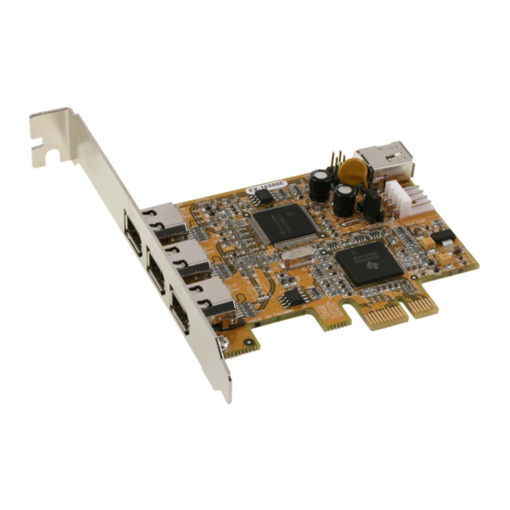
BESCHREIBUNG & TECHNISCHE DATEN
Die EX-16500E ist eine FireWire 1394a PCI-Express Karte. Sie ist extern mit 3 und intern mit 1
FireWire 1394a Port ausgestattet. Sie unterstützt alle PCI-Express Slots von x1 bis x16. Der
serielle PCI-Express Bus unterstützt optimal die Leistung des schnellen Texas Instruments
Chipset. Die EX-16500E gewährleistet so eine sichere Datenübertragung und exzellente Perfor-
mance von bis zu 400 Mbit/s! Es ist nicht möglich die I/O Adressen und Interrupts manuell
einzustellen, da die Einstellungen der Karte vom System (BIOS) und beim installieren des
Betriebssystems automatisch vorgenommen werden.
Kompatibilität:
Betriebssysteme:
Anschlüsse:
Lieferumfang:
Zertifikate:
JUMPER EINSTELLUNG & ANSCHLÜSSE
JP1:
J7:
J2 / J3 / J4 / J5:
6
EX-16500E
Anleitung
Vers. 2.3 / 16.10.17
J6: 1 x interne Pfostenstcker
für Front Bay Hubs
(Wird mit dem internen
Anschluss J2 geteilt)
J5: 1 x 6 Pin 1394a Buchse
PCI-Express x1 bis x16
Windows ME/ 2000/ XP/ Vista/ 7/ 8.x/ 10/ Server 20xx/ MAC/ Linux
3x 6 Pin 1394a extern, 1x 6 Pin 1394a intern, 1x 10 Pin Pfostenstecker
EX-16500E, Anleitung, Low Profile Bügel
CE / FCC / RoHS / WEEE
DE97424562 / WHQL
PCIE = Strom vom PCI-Express BUS (Werkseinstellung)
AUX = Strom vom PC-Netzteil des Rechners
(Zur Entlastung des Mainboards und zur stabilen Stromversorgung bei
PCIE AUX
Verwendung von Endgeräten mit hohem Stromverbrauch)
Anschluss J7 muss dann mit dem PC-Netzteil verbunden werden!
1 +5V
Für AUX Einstellung (JP1) muss J7 mit PC-Netzteil verbunden werden!
2 GND
Sonst wird die Karte nicht mit Strom versorgt.
3 GND
4 +12V
6 Pin FireWire 1394a Buchse
Pin
Signal
Pin
1
Power
4
2
GND
5
3
TPB-
6
1
J2: 1 x 6 Pin 1394a Buchse
(Wird mit dem externen
Anschluss J3 geteilt)
J7: Anschluss für
Stecker vom
PC-Netzteil
JP1: Stromquelle wählen
PCI-E oder AUX
Signal
TPB+
TPA-
TPA+
Advertisement

Related Manuals for Exsys EX-16500E


Summary of Contents for Exsys EX-16500E
- Page 1 Gently replace your computer’s cover and the mounting screws. Die EX-16500E ist eine FireWire 1394a PCI-Express Karte. Sie ist extern mit 3 und intern mit 1 FireWire 1394a Port ausgestattet. Sie unterstützt alle PCI-Express Slots von x1 bis x16. Der serielle PCI-Express Bus unterstützt optimal die Leistung des schnellen Texas Instruments...
- Page 2 Kurzschluss entsteht. Danach befestigen Sie die Karte mit einer Schraube am Gehäuse. Die EX-16500E is a plug & play high-speed FireWire IEEE1394a expansion card for the PCI- Jetzt können Sie das Computergehäuse mit den Schrauben wieder schließen.
Need help?
Do you have a question about the EX-16500E and is the answer not in the manual?
Questions and answers