Hella Gutmann SEG V Operating Instructions Manual
Hide thumbs
Also See for SEG V:
- User manual (1212 pages) ,
- Information sheet (39 pages) ,
- User manual (1106 pages)

Related Manuals for Hella Gutmann SEG V


Summary of Contents for Hella Gutmann SEG V
- Page 1 SEG V Operating instructions Original operating instructions BD0069V0000EN0816S0 460 985-24 / 08.16...
-
Page 2: Table Of Contents
Marking of text parts ......................5 2 User information ..........................6 Safety precautions .......................6 2.1.1 General safety precautions.......................6 2.1.2 Safety precautions for the SEG V....................6 2.1.3 Safety precautions – high voltage and line voltage ...............7 2.1.4 Safety precautions – risk of injury .....................7 2.1.5 Safety precautions –... - Page 3 Symbols ..........................26 7.1.1 General symbols ........................26 7.1.2 Symbols in the header......................28 7.1.3 Symbols in the Main menu ..................... 29 7.1.4 Headlight test symbols......................29 Preparing headlight test ..................... 30 7.2.1 Dimensions for vehicle set-up area and SEG V................30...
- Page 4 Table of contents SEG V 7.2.2 Floor space for stationary SEG V..................... 31 7.2.3 Vehicle test ......................... 32 7.2.4 Setting dimensions and tolerances ..................33 Aligning the SEG V ......................35 7.3.1 Switching on the laser......................35 7.3.2 Aligning the optic housing to the vehicle................... 35 7.3.3...
-
Page 5: About This Manual
SEG V About this manual Reading the manual 1 About this manual Reading the manual Please read the user manual completely. Pay special attention to the first pages containing the safety instructions and the conditions of liability. They are provided solely to assure your safety when working with the tool. -
Page 6: User Information
Protect the tool from strong impacts (do not drop or knock over). • Do not open the tool on your own. Only technicians authorised by Hella Gutmann are allowed to open the tool. If the protective seal is damaged or if the tool is subject to unauthorised intervention, the warranty will be rendered void. -
Page 7: Safety Precautions - High Voltage And Line Voltage
SEG V User information Safety precautions 2.1.3 Safety precautions – high voltage and line voltage Very high voltages occur in electrical systems. Due to voltage flashover on damaged components such as marten damage or touching live components, there is a risk of electric shock. High voltage via the vehicle and line voltage via the building's mains supply can cause severe injury or even death if adequate care is not taken. -
Page 8: Disclaimer
User information SEG V Disclaimer Disclaimer 2.2.1 Software 2.2.1.1 Safety-relevant software modifications The current tool software provides numerous diagnostic and configuration functions. Some of these functions affect the behaviour of electronic components. These components also include components in safety related vehicle systems, such as airbags and brakes. -
Page 9: Prohibition Of Safety-Related Software Modifications
There are doubts about the correct function of the safety-related software modification. • The tool is transferred to a third party. Hella Gutmann Solutions GmbHis unaware of the fact and has not authorised the third party to use the diagnostic program. -
Page 10: Documentation
Solutions GmbH does not accept any liability for failed or unnecessary repair work. Hella Gutmann Solutions GmbH does not accept any liability for the use of data and information that is found to be incorrect or that was incorrectly displayed, or for errors that occurred inadvertently during the compilation of the data. -
Page 11: Tool Description
Never put the tool into operation if you suspect that there are loose parts in or on the tool. Inform the Hella Gutmann trading partner or the Technical Support of Hella Gutmann immediately. Please check the delivery contents upon receiving your tool so that complaints regarding any potential damage can be made immediately. -
Page 12: Intended Use
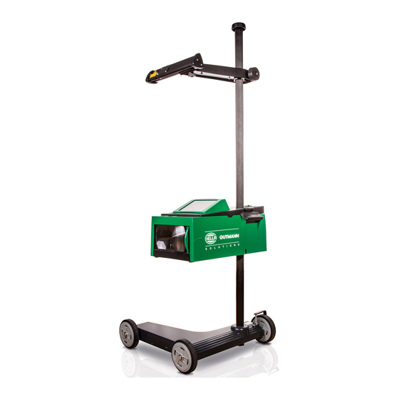
The SEG V is a mobile tool for testing all modern headlight systems of vehicles. The SEG V is equipped with a modern camera system. This enables precise testing of halogen, xenon and LED headlight systems with the various light distribution functions such as low beam, main beam and fog light but also the vertical light/dark boundary. -
Page 13: Tool Overview
The laser can be switched on here. Laser sight The laser is integrated into the mirror mount. SEG V is correctly oriented if the line laser pointer is parallel to two symmetrical reference points on the front side of the vehicle. -
Page 14: Setting The Optic Housing Height
Tool description SEG V Setting the optic housing height USB interface Updates can be loaded here from a USB stick or reports can be saved onto a USB stick via this USB interface. Optic housing ON/OFF button of the optic housing Switch on the tool here. -
Page 15: Switching On The Laser
After turning on the laser sight, the laser output is activated for approx. 30 s via an integrated time switch. Within this time, SEG V can be aligned in front of the vehicle. To switch on the laser, proceed as follows: 1. -
Page 16: Most Important Symbols
Tool description SEG V Most important symbols 3.10 Most important symbols M M e e a a n n i i n n g g S S y y m m b b o o l l s s Arrow keys Navigate with the cursor in menus or functions. -
Page 17: Assembly
SEG V Assembly Assembling the SEG V 4 Assembly Assembling the SEG V 1. Place the column (3) with thrust ring (6) and clamping piece (4) in the socket (7). NOTE Colour markings on the column and tool foot must align. -
Page 18: Putting Into Operation
Putting into operation SEG V Charging the battery 5 Putting into operation This section gives a description of how to switch on and off the tool as well as all the necessary steps for the first use of the tool. -
Page 19: Configuring The Tool
SEG V Configuring the tool Entering vehicle data 6 Configuring the tool Configure all interfaces and functions under Settings in the main menu. Entering vehicle data Enter data for the quick test and the document test here. To enter or change vehicle data, proceed as follows: 1. -
Page 20: Configuring The Language
Configuring the tool SEG V Configuring the country 2. Open list under Country with The selection of countries depends on the specific software. 3. Select the country for the corresponding language. The selection is saved automatically. 6.2.2 Configuring the language Here the language can be configured if the software is multilingual (optional). -
Page 21: Setting The Time
SEG V Configuring the tool Configuring company data 1. Select Settings > Region in the main menu. 2. Open the selection window under Date with 3. Select the desired day under Day by using 4. Repeat steps 2 and 3 for Month and Year. -
Page 22: User Name
SEG V Configuring the tool User name User name 6.4.1 Entering the user name Here you can manage the different users. Proceed as follows to enter the user name: 1. In the main menu, select Settings > User. 2. Click to open the virtual keypad. -
Page 23: Level Compensation
2. Open the selection window under Level compensation with 3. Open the list with 4. Select >Automatic<. The level of the vertical and horizontal axis adjusts automatically, so that any unevenness in the SEG V set-up area is compensated for. 5. Confirm the selection with . -
Page 24: Searching For And Installing A Wlan Interface
The WLAN configuration is tested. If the WLAN configuration has been tested successfully, then the address of the selected WLAN is displayed under SEG V - IP address. 6.6.3 Resetting the WLAN configuration The WLAN configuration can be reset here. -
Page 25: Updating The Tool
The tool searches for a new update that is then downloaded and installed. The tool switches off and on again after the successful system update. The installation is checked automatically after startup. Service menu The Service menu is exclusively reserved for Hella Gutmann service technicians or the testing organizations. -
Page 26: Working With The Tool
Working with the tool SEG V Symbols 7 Working with the tool Symbols 7.1.1 General symbols S S y y m m b b o o l l s s M M e e a a n n i i n n g g Info Information on the contents of the respective menu can be displayed here. - Page 27 SEG V Working with the tool Symbols S S y y m m b b o o l l s s M M e e a a n n i i n n g g Virtual keypad Open the virtual keypad for text input.
-
Page 28: Symbols In The Header
Working with the tool SEG V Symbols 7.1.2 Symbols in the header M M e e a a n n i i n n g g S S y y m m b b o o l l s s Vehicle data This menu contains the data of the currently selected vehicle. -
Page 29: Symbols In The Main Menu
SEG V Working with the tool Symbols 7.1.3 Symbols in the Main menu M M e e a a n n i i n n g g S S y y m m b b o o l l s s Home Return directly to the main menu. -
Page 30: Preparing Headlight Test
Following the regulation, valid from January 2015, with regards to adjustment of vehicle headlights, in line with §29 of the German Road Traffic Licensing Regulation (StVZO) (MOT test headlight testing directive), the testing and set-up area are defined as follows for the vehicle and SEG V: Fig. 1 Dimensions for vehicle set-up area... -
Page 31: Floor Space For Stationary Seg V
• Rails are mounted on the ground. • When used as a rail unit, a rail guide set must be ordered for each SEG V (order no. 9XS 861 736-001). The rail serves as a drill template during assembly. •... -
Page 32: Vehicle Test
Working with the tool SEG V Preparing headlight test • Vehicle floor surface and rail level for SEG V must lie parallel to another in both expansions. • The height difference from the rolling tread must correspond to legal specifications. •... -
Page 33: Setting Dimensions And Tolerances
SEG V Working with the tool Preparing headlight test 7.2.4 Setting dimensions and tolerances Fig. 5 Setting dimension in cm by which the light-dark border must be inclined at a distance of 10 m. H = Height of the centre of the headlight over the floor surface in cm. - Page 34 Working with the tool SEG V Preparing headlight test Vehicle type Headlight setting dimension Tolerances Vehicles acc. to Vehicles acc. to no. 1 and 2 — [%] no. 1 and 2 — [%] no. 3 and 4 — [cm] no. 3 and 4 — [cm]...
-
Page 35: Aligning The Seg V
7.3.2 Aligning the optic housing to the vehicle Fig. 6 To align the optic housing to the vehicle, proceed as follows: 1. Position the SEG V with a distance of 30 to 70 cm in front of the headlight. CAUTION Laser radiation Damage to/destruction of the retina Never look directly into the laser beam. -
Page 36: Adjusting The Height Of The Laser Sight
7.3.3 Adjusting the height of the laser sight The laser sight provides the option to align the SEG V and headlamp using a laser pointer. Two parallel points on the vehicle front can be determined with the generated light band. If the required power supply (9 V block battery, 9 V type) is not available, then the alignment can be carried out using the broad-band sight. -
Page 37: Aligning The Optic Housing To Commercial Vehicles
• Section Preparing headlight test (Page 30) is complete. • Section Aligning the SEG V (Page 35) is complete. 7.4.2 Carrying out a documented test NOTE A documented test can only be carried out when company data has been entered. -
Page 38: Creating A Report
SEG V Working with the tool Documented test 4. Call up the vehicle database with NOTE The manufacturer, fuel type and model must be selected, as a minimum. 5. Select the required manufacturer. 6. Select the required fuel type. 7. Select the required model. -
Page 39: Quick Test
SEG V Working with the tool Quick test 1. Insert the USB stick into the USB port on the SEG V. 2. Select >Documented test< in the main menu. 3. Call up Car history with Alternatively, search for the vehicle via Vehicle owner or Licence plate. -
Page 40: Audi Matrix Led Headlights
Working with the tool SEG V Audi Matrix LED headlights 5. Open Headlight selection with 6. Perform the headlight test as described in the section Performing headlight test (Page 43). Audi Matrix LED headlights For the Audi Matrix LED headlights, adjusting screws are no longer available for setting the main beam distribution. -
Page 41: Bmw Dynamic Light Spot
SEG V Working with the tool BMW Dynamic Light Spot BMW Dynamic Light Spot In the dark, the Dynamic Light Spot marking light system from BMW detects people from a distance and lights them in a targeted way. Two separately controlled powerful spotlights are focused as one on unlit persons. People are detected promptly in the dark, offering higher levels of safety. - Page 42 Working with the tool SEG V BMW Dynamic Light Spot 7. In the vehicle setting options, correct the headlight setting according to the recommended settings using the direction arrows on the test screen. Adjust the headlight upwards Green symbol: no correction necessary...
-
Page 43: Performing Headlight Test
SEG V Working with the tool Performing headlight test Performing headlight test 7.8.1 Preconditions for headlight tests Observe the following to perform headlight tests: • All preconditions for testing are fulfilled (refer to Preparing for headlight test (Page 30)). •... -
Page 44: Performing Main Beam Headlight Test
Working with the tool SEG V Performing headlight test 2. Start the headlight test via 3. Observe the confirmation prompt. 4. Confirm the confirmation prompt with Light distribution from the headlight is displayed on the test screen. 5. In the vehicle setting options, correct the headlight setting according to the recommended settings using the direction arrows on the test screen. -
Page 45: Performing Fog Light Test
SEG V Working with the tool Performing headlight test 2. Start the headlight test via 3. Observe the confirmation prompt. 4. Confirm the confirmation prompt with Light distribution from the headlight is displayed on the test screen. 5. In the vehicle setting options, correct the headlight setting according to the recommended settings using the direction arrows on the test screen. -
Page 46: Performing Adaptive Light Control Test
Working with the tool SEG V Performing headlight test 2. Start the headlight test via 3. Observe the confirmation prompt. 4. Confirm the confirmation prompt with Light distribution from the headlight is displayed on the test screen. 5. In the vehicle setting options, correct the headlight setting according to the recommended settings using the direction arrows on the test screen. - Page 47 SEG V Working with the tool Performing headlight test 1. Run through steps 1–6 as described in the section Performing quick tests. 2. Open the list under Adaptive headlights via 3. Select >Yes<. 4. Open Headlight selection with 5. Switch on headlights with adaptive light control on the vehicle.
-
Page 48: Performing Headlight Test With 10 Metre Wall
Working with the tool SEG V Performing headlight test 7.8.7 Performing headlight test with 10 metre wall The headlight test with the 10-metre wall is mainly used for vehicles for which the upper edge of the mirror on the headlights is higher than 140 cm above the floor surface. - Page 49 SEG V Working with the tool Performing headlight test 1.00 1.10 0.95 1.25 1.30 1.22 1.37 1.40 1.36 1.07 1.17 1.02 1.33 1.38 1.30 1.47 1.50 1.46 1.13 1.23 1.08 1.42 1.47 1.39 1.56 1.59 1.55 1.20 1.30 1.15 1.50 1.55...
-
Page 50: General Information
Display may be defective. Inform the Hella Gutmann trading partner or the Technical Support of Hella Gutmann. Care and maintenance Like any tool, the SEG V must be treated with care. Therefore observe the following: • Clean the tool regularly with mild cleaning detergents. - Page 51 SEG V General information Care and maintenance 3. Pull out the 9 V block battery. 4. Dispose of the old 9 V block battery in an environmentally friendly way. NOTE Pay attention to correct installation direction/polarity 5. Insert the new 9 V block battery.
-
Page 52: Service Parts And Accessories
Tool test SEG V must be tested in two year intervals. SEG V must only be calibrated or maintained by one competent authority or institution. In the event of questions regarding testing or maintenance contact a national calibration authority, Hella Gutmann trading partner or the Technical Support of Hella Gutmann. -
Page 53: Disposal
Since, in the case of the present device, this relates to exclusively commercially used equipment (B2B), it must not be handed over to a public disposal facility. The tool can be disposed of at the following address (specifying the date of purchase and the device numbers): Hella Gutmann Solutions GmbH Am Krebsbach 2 79241 Ihringen GERMANY WEEE reg. -
Page 54: Technical Data
General information SEG V Technical data Technical data Supply voltage 115-230 V ~/50-60 Hz Power supply Lead battery, internal power adapter Battery life 8 to 10 h Battery capacity 7.2 Ah Construction type: LCD-TFT Display Size: 8.4 inch Input Touch screen Ambient temperature Recommended: 10 - 35°C... - Page 55 SEG V Notes...
- Page 56 HELLA GUTMANN SOLUTIONS GMBH Am Krebsbach 2 79241 Ihringen GERMANY Phone: +49 7668 9900–0 Fax: +49 7668 9900–3999 info@hella-gutmann.com www.hella-gutmann.com © 2016 HELLA GUTMANN SOLUTIONS GMBH 1 STUECK/PIECE(S) ���� ��� �������� 9XQ 460 985-241 Made in Germany...
Need help?
Do you have a question about the SEG V and is the answer not in the manual?
Questions and answers