Table of Contents
Advertisement
Advertisement
Table of Contents

Related Manuals for Hella Gutmann SEG IV


Summary of Contents for Hella Gutmann SEG IV
- Page 1 SEG IV 8PA 007 732–301 ...–311 Instruction manual BD0056V0002EN0315S0...
-
Page 2: Table Of Contents
Table of contents Table of contents 1 Assembly ........................ 3 2 Description of parts ....................4 3 Floor area ....................... 5 Even floor surface (in compliance with ISO 10 604) for mobile beamsetters in zero position ..........................5 Level, horizontal floor space for SEG 4 DLLX ................6 Floor surface for permanently installed beamsetters ............... -
Page 3: Assembly
Assembly 1 Assembly 1. Insert the column (1) with the pressure disc (2) and the clamping piece (3) into the bush (4) einsetzen. NOTE The coloured markings on the column and the base must be in line with one another. Tap the fixing pin (5) (fastened to the base of the unit with adhesive tape) into the drilled... -
Page 4: Description Of Parts
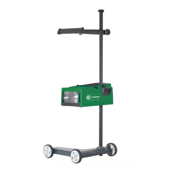
Description of parts 2 Description of parts Type 8PA 007 732-311 Headlight aiming device with rubber castors, laser sight, digital light meter, laser positioning aid and eccentric axle. Type 8PA 007 732-301 Headlight aiming device with rubber castors, broad-band sight, digital light meter and laser positioning aid. -
Page 5: Floor Area
Floor area Even floor surface (in compliance with ISO 10 604) for mobile beamsetters in zero position 3 Floor area Even floor surface (in compliance with ISO 10 604) for mobile beamsetters in zero position CAUTION! The construction and condition of the floor areas are of vital importance for correct headlamp setting. -
Page 6: Level, Horizontal Floor Space For Seg 4 Dllx
Floor area Level, horizontal floor space for SEG 4 DLLX Level, horizontal floor space for SEG 4 DLLX To achieve an exact headlamp adjustment with the SEG 007 732-311, the following requirements for the floor space apply: The bubble level in the SEG optics box must be adjusted to a central position of the air bubble by means of the hand lever (for each... -
Page 7: Floor Surface For Permanently Installed Beamsetters
Floor area Floor surface for permanently installed beamsetters Floor surface for permanently installed beamsetters Beamsetters have also been designed for permanent installation. The rails are mounted firmly on the floor. If the beamsetter is to be used together with its rails, one set of rails must be ordered for each beamsetter (part no. -
Page 8: Setting Up And Alignment
Setting up and alignment Preparation of the vehicle 4 Setting up and alignment Preparation of the vehicle NOTE National road traffic regulations must always be heeded. The vehicle tyres must have the prescribed pressure! The vehicle should be loaded as follows: •... -
Page 9: Setting Up
Setting up and alignment Setting up Setting up 1. Move the beamsetter into position in front of the headlamp to be checked. 2. align the beamsetter box with the middle of the headlamps. It must not be more than 3 cm out of line horizontally or vertically. -
Page 10: Checking And Setting Headlamps (National Regulations Must Be Observed)
Checking and setting headlamps (National regulations must be observed) Setting up 5 Checking and setting headlamps (National regulations must be observed) NOTE The headlight aiming device can be used to inspect all headlight systems, including DE, FF, LED and XENON headlights. The rectangle drawn on the test screen corresponds to the size of the test surface which is mandatory under the Directive for the adjustment of vehicle headlamps. - Page 11 Checking and setting headlamps (National regulations must be observed) Setting up Vehicle type Headlight setting dimension Tolerances Vehicles acc. to Vehicles acc. to no. 1 and 2 — [%] no. 1 and 2 — [%] no. 3 and 4 — [cm] no.
- Page 12 Checking and setting headlamps (National regulations must be observed) Setting up a) Headlamps with symmetrical dipped beams Dipped beam 1. Align the beamsetter as described in Section 4.0. 2. Set the scale wheel as shown on the adjustment table. 3. Switch on dipped beam: The cut-off line must run as near as possible to the horizontal along the whole of the dividing line and the whole width of the screen.
- Page 13 Checking and setting headlamps (National regulations must be observed) Setting up c) Fog lamps Fog light 1. Align the beamsetter as described in Section 4.0. 2. Set the scale wheel as shown on the adjustment table. 3. Switch on the fog lamp: The cut-off line must run as near as possible to the horizontal along the whole of the dividing line and the whole width of the screen.
- Page 14 Checking and setting headlamps (National regulations must be observed) Setting up +/- degrees Percent Angular +/- degrees Percent Angular minutes minutes 0,17 4,54 0,34 4,71 0,52 4,89 0,69 5,06 0,86 5,24 1,04 5,41 1,22 5,59 1,39 5,76 1,57 5,94 1,74 6,11 1,92 6,29...
-
Page 15: Using The Luxmeter And Positioning Aid
Using the Luxmeter and positioning aid Photoelectric Luxmeter 6 Using the Luxmeter and positioning aid Photoelectric Luxmeter Following adjustment of the lamp, the photoelectric Luxmeter can be used to check that the maximum permissible glare value on dipped beam is not exceeded and the main beam is within the minimum / maximum illuminance levels. NOTE! Before the light values are checked, a visual inspection of the headlamps must be carried out. -
Page 16: Positioning Aid
Using the Luxmeter and positioning aid Positioning aid Positioning aid Switching on the laser Laser voltage supply: Customary trade monoblock 9V battery (not supplied). 1. Turn the scaled wheel anticlockwise as far as it will go and hold it there. 2. -
Page 17: Additional Instructions
Additional instructions Vehicles on which the upper edge of the headlamps is more than 140 cm above the floor 7 Additional instructions Vehicles on which the upper edge of the headlamps is more than 140 cm above the floor NOTE National road traffic regulations must always be heeded. - Page 18 Additional instructions Vehicles on which the upper edge of the headlamps is more than 140 cm above the floor Setting dimension when the height of the dipped headlights and main beam headlights is above 1.4 m H [m] E = 10 m E = 5 m E = 2,5 m h [m]...
-
Page 19: Checking The Beamsetter
Additional instructions Checking the beamsetter Checking the beamsetter Beamsetters are fully adjusted and calibrated before they leave the factory. However, when they are in use in a garage, it can happen that they come out of calibration if not handled properly, e.g. by being knocked over). It is therefore advisable to have the beamsetter checked using the adjusting machine 8 PD 860 757-001 at regular intervals, e.g. -
Page 20: Spare Parts
Spare parts Checking the beamsetter 8 Spare parts 1. Hand-wheel for sight holder 9SG 855 498–001 2. Hand-wheel for locking column in position 9SG 855 454–011 3. Button 9ST 861 074–001 4. Sight 8PV 861 112-021 5. Sight with holder 8PV 861 078-021 6. - Page 21 If you have any questions: Phone the Hella Customer Service Department.
- Page 22 HELLA GUTMANN SOLUTIONS GMBH Am Krebsbach 2 79241 Ihringen GERMANY Phone: +49 7668 9900–0 Fax: +49 7668 9900–3999 info@hella-gutmann.com www.hella-gutmann.com © 2015 HELLA GUTMANN SOLUTIONS GMBH...
Need help?
Do you have a question about the SEG IV and is the answer not in the manual?
Questions and answers