
Subscribe to Our Youtube Channel
Related Manuals for uAvionix RT-2087/ZPX-A


Summary of Contents for uAvionix RT-2087/ZPX-A
- Page 1 RT-2087/ZPX-A User and Installation Guide UAV-1005667-001 Rev A ECCN 7A994 Page 1 | 48...
- Page 2 retained.
-
Page 3: Revision History
RT-2087/ZPX-A User and Installation Guide 1 Revision History Revision Date Comments 30 Jun 2021 Initial release. UAV-1005667-001 Rev A ECCN 7A994 Page 3 | 48... -
Page 4: Warnings / Disclaimers
RT-2087/ZPX-A User and Installation Guide 2 Warnings / Disclaimers All device operational procedures must be learned on the ground. uAvionix is not liable for damages arising from the use or misuse of this product. This equipment is classified by the United States Department of Commerce's Bureau of Industry and Security (BIS) as Export Control Classification Number (ECCN) 7A994. -
Page 5: Limited Warranty
RT-2087/ZPX-A User and Installation Guide 3 Limited Warranty uAvionix products are warranted to be free from defects in material and workmanship for two years from the installation of ZPX-A in or on the platform. For the duration of the warranty period, uAvionix, at its sole discretion, will repair or replace any product which fails in normal use. -
Page 6: Table Of Contents
RT-2087/ZPX-A User and Installation Guide 4 Contents 1 Revision History ................. 3 2 Warnings / Disclaimers ............... 4 3 Limited Warranty ................5 4 Contents ..................... 6 5 System Information ................9 Certification Applicability ............... 9 AIMS-Certified Performance ............9 Applicable P/Ns ................ - Page 7 RT-2087/ZPX-A User and Installation Guide Serial Data Interfaces ................ 19 7 Installation ..................20 Unpacking and Inspecting ............20 Applicable Part Numbers ............20 Installation Material and Tools ............ 20 Additional Required Equipment ........... 21 Mounting ..................21 Wiring ..................22 Wiring Diagram ..................
- Page 8 RT-2087/ZPX-A User and Installation Guide 10.1.13 Default Squawk ..............33 10.1.14 Baro Altitude Resolution ............33 10.1.15 In / Out Protocols ..............33 10.2 Control ..................34 10.3 Post-Installation Checks.............. 35 10.4 Altitude Encoder Calibration ............37 11 Normal Operation ................38 12 Maintenance ..................
-
Page 9: System Information
5.1 Certification Applicability This installation manual provides mechanical and electrical information necessary to install the RT-2087/ZPX-A (ZPX-A). It is not equivalent to an approved, airframe-specific maintenance manual, installation design drawing, or installation data package. The content of this manual assumes... -
Page 10: Applicable P/Ns
RT-2087/ZPX-A User and Installation Guide Function Document Class AIMS “Civil-Only Capability” Transponder AIMS 17-1000, Modes 3/A, C, S ELS, and Requirements App. G, §1.1 ADS-B Out AIMS 1101 AIMS 1101 Test §5.21 is AIMS Test Standard for UAS X-Bit Control §1.8.1... -
Page 11: Deviations
RT-2087/ZPX-A User and Installation Guide 5.5 Deviations Deviations from TSO and AIMS 17-1000 requirements are noted below. Doc. Deviation From TSO-C112e paragraphs 3.e and 6.f to use DO-178C C112e instead of DO-178B Anticipating DO-181F for a Level 2 “Basic Transponder”, UM... -
Page 12: Fcc Id
RT-2087/ZPX-A User and Installation Guide Doc. Deviation Barometric pressure altitude is limited to 101,350 ft rather than 17-1000 126,750 ft [ref: AIMS 17-1000, §4.9.8 (Altitude Transmission)]. ZPX-A is a non-diversity, single channel transponder and should be installed only on platforms that can meet antenna... -
Page 13: Environmental Qualification Form
RT-2087/ZPX-A User and Installation Guide 5.7 Environmental Qualification Form Test Description DO-160G Category / Value Temperature and Altitude Equipment tested to Categories B2, C4 Low temperature ground survival 4.5.1 -55°C Low Temperature Short-Time 4.5.1 -35°C Operating Low Temperature Operating 4.5.2 -35°C (see Note 1) -
Page 14: Continued Airworthiness
RT-2087/ZPX-A User and Installation Guide 5.8 Continued Airworthiness Maintenance of the ZPX-A is "on condition" only. Periodic regulatory function checks of the transponder and altitude encoder must be performed. Every 24 months, or after any maintenance is performed where data correspondence error could be introduced: 1. -
Page 15: System Limitations
RT-2087/ZPX-A User and Installation Guide 5.9 System Limitations Installation This article meets the minimum performance and quality control standards required by DoD AIMS 17-1000. If installing this article on or in a specific type or class of aircraft, separate approval for installation is required. As an example, for a military UAS to gain platform approval requires verification of functionality and performance in accordance with AIMS 1102 and 1103. -
Page 16: System Specifications
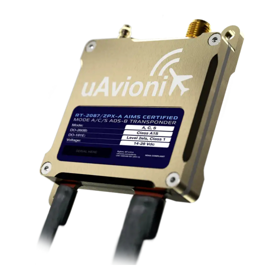
RT-2087/ZPX-A User and Installation Guide 6 System Specifications 6.1 System Functionality ZPX-A is a Mode S, Level 2els, Class 1 transponder with support for ADS- B extended squitter, elementary surveillance, and SI code. A control that provides for enabling X-bit for Mode 3/A replies is provided. The nominal conducted power output is about 54 dBm, meaning AIMS 17-1000 App. -
Page 17: Mode S Transponder Specification
RT-2087/ZPX-A User and Installation Guide Mode S Transponder Specification Characteristic Specification Transmit frequency 1090 MHz ~54 dBm – Class 1 Transmit power Transponder Level 2els Receive frequency 1030 MHz AIMS Certified Modes 3/A, C, S ELM, ES ADS-B OUT ATCRBS sensitivity... -
Page 18: Internal Altitude Sensor/Encoder Specification
RT-2087/ZPX-A User and Installation Guide Internal Altitude Sensor/Encoder Specification Characteristic Specification -1,000 ft to 35,000 ft TSO-C88b Operating Range (for TSO compliance) Maximum Differential Pressure 36,000 ft Altitude (static port to installation environment) Maximum Rate of Altitude Change 20,000 fpm... -
Page 19: Serial Data Interfaces
MavLink RX [0xCA, Length 51] Navigation Data 115200 bps Note: • Details of the UCP packets can be found in UAV-1002375-001 uAvionix UCP Transponder Interface Control Document (Rev. T or later). • Details of the Navigation Data Message can be found in UAV-1001912-001 uAvionix MavLink OEM Protocol ICD. -
Page 20: Installation
RT-2087/ZPX-A User and Installation Guide UAV-1005667-001 7.3 Installation Material and Tools ZPX-A requires configuration, either using the available uAvionix Windows- based application, or dynamically using the described configuration protocol. Typical installations will be configured using: • Ping200X Control & Config” Windows application •... -
Page 21: Additional Required Equipment
RT-2087/ZPX-A User and Installation Guide • Environmental splices • Ring terminals for grounding • Static pressure lines and fittings • Thread locking compound. (We recommend Loctite® 242 or 243 which works well with stainless steel hardware.) Minimally, ZPX-A installation requires access to the following tools: •... -
Page 22: Wiring
RT-2087/ZPX-A User and Installation Guide • Select a position in the aircraft not too close to any high external heat source. ZPX-A is not a significant heat source itself and does not need to be kept away from other devices for this reason. -
Page 23: Wiring Diagram
RT-2087/ZPX-A User and Installation Guide If new power wiring is required, refer to AC 43.13-1B Chapter 11 for guidance. The wiring should present an impedance of less than 0.5 Ω. The following table provides guidance for typical aircraft hook-up wire. -
Page 24: Transponder
• The antenna should be mounted external to the airframe, and typically on the bottom of the aircraft. The antenna should be mounted in a vertical orientation when the aircraft is in level flight. For uAvionix UAV-1004675-001, see below for proper orientation. UAV-1005667-001 Rev A... -
Page 25: Static Pressure Port
RT-2087/ZPX-A User and Installation Guide • Keep the cable lengths as short as possible and avoid sharp bends in the cable to minimize the Voltage Standing Wave Ratio (VSWR) (i.e., Return Loss). • Ensure that cable and connector losses do not reduce power output below allowed levels for your aircraft operation. -
Page 26: Cooling Requirements
RT-2087/ZPX-A User and Installation Guide 7.9 Cooling Requirements ZPX-A is designed to meet all applicable performance requirements without forced-air cooling. Attention should be given, however, to the incorporation of cooling provisions to limit the maximum operating temperature if ZPX-A is installed in close proximity to other avionics which would otherwise cause operational temperature limits to be exceeded [see §5.7 (Environmental... -
Page 27: Configuration And Calibration
RT-2087/ZPX-A User and Installation Guide “Maintenance Required” failure. If no position data is provided, certain ADS-B messages will be incomplete. Care must be taken to ensure the position source is qualified to meet ADS- B regulations for your operation, and that the ZPX-A is appropriately configured (SIL/SDA value). -
Page 28: Configuration
RT-2087/ZPX-A User and Installation Guide Make sure that the COM settings on the control tab match the serial port assigned to the USB adapter Click ‘Start’. 10.1 Configuration The Configuration Items List below should be used to document the system installation for future reference. -
Page 29: Icao Address
RT-2087/ZPX-A User and Installation Guide Configuration Item Default Configured ICAO Address 0x000000 Aircraft Maximum Speed (kts) < 75 Aircraft Stall Speed L ≤ 15 + W ≤ 23 Aircraft Length + Width (m) “ “ Aircraft Registration GPS Antenna Lateral Offset (m) -
Page 30: Aircraft Maximum Speed
RT-2087/ZPX-A User and Installation Guide Tip: By using the N-Number Look Up function on https://www.faa.gov, locate and use the “Mode S Code (Base 16 / hex)” value. Applies to U.S. registered civilian aircraft only. 10.1.2 Aircraft Maximum Speed Mode S transponders can transmit their maximum airspeed characteristics to aircraft equipped with TCAS. -
Page 31: Aircraft Registration
RT-2087/ZPX-A User and Installation Guide 10.1.5 Aircraft Registration The Aircraft Registration can be up to an 8 alpha-numeric code that corresponds to the tail number of the aircraft. Note: This is typically the civilian aircraft N-number or military equivalent, unless otherwise advised by the FAA or ATC. -
Page 32: Aircraft Emitter Type
RT-2087/ZPX-A User and Installation Guide 10.1.7 Aircraft Emitter Type The aircraft emitter type default is ‘No Information Available’. This must be configured as appropriate for the host aircraft. 10.1.8 ADS-B In Capability The ADS-B transmissions include an indication to the ground stations of whether the aircraft includes a 1090 MHz ADS-B receiver, a UAT ADS-B receiver, or both. -
Page 33: Default Control Mode
RT-2087/ZPX-A User and Installation Guide 10.1.12 Default Control Mode Select the default operating mode, to be used prior to arrival of control messages. This setting configures the ZPX-A for Mode A, Mode C, Mode S and ADS-B Extended Squitter transmissions. -
Page 34: Control
RT-2087/ZPX-A User and Installation Guide 10.2 Control The Control tab allows the installer to exercise and verify the transponder’s operation. This simulates a control head, control panel of a GCS, or similar equipment. Ownship Display Serial Port Setup Packet Statistics... -
Page 35: Post-Installation Checks
RT-2087/ZPX-A User and Installation Guide 10.3 Post-Installation Checks Post-installation checks must be performed by the installer, after configuration, as appropriate for the aircraft and type of installation. To ensure compliance with civil regulations in the United States, verify functionality identified in 14 CFR Part 43 Appendix F (ATC Transponder Tests and Inspections) and 14 CFR Part 43 Appendix E (Altimeter System Test and Inspection). - Page 36 RT-2087/ZPX-A User and Installation Guide STEP CHECK Confirm ‘Baro Altitude’ in ‘Ownship Display’ shows the current pressure altitude; i.e., the current altitude as displayed on an altimeter set to 29.92 If a GPS is connected and the GPS antenna has a clear view of the sky, allow the GPS time to obtain a position fix;...
-
Page 37: Altitude Encoder Calibration
RT-2087/ZPX-A User and Installation Guide 10.4 Altitude Encoder Calibration STEP CHECK Launch the ‘ping200X Control & Config’ Windows Application Set Port to the USB or serial port connected to the ZPX-A Set the ‘App Baud’ to value noted in Section 10.1 Set ‘Protocol’... -
Page 38: Normal Operation
ZPX-A should be enabled, typically in ALT mode, during all phases of flight, , including surface movement operations. Maintenance ZPX-A is not a user serviceable product. All service must be performed either by uAvionix or an authorized uAvionix repair center. Support For additional questions or support please visit: https://www.uavionix.com/support/... -
Page 39: Appendix A Control Interface
Transponder Configuration message. UCP or UCP-HD input is required to be enabled to allow device configuration. uAvionix Control Protocol (UCP) is documented in uAvionix UCP Transponder Interface Control Document UAV-1002375-001 (Rev. T or later). This document is available to authorized parties and may be obtained by contacting uAvionix. - Page 40 RT-2087/ZPX-A User and Installation Guide Mode To set the transponder operating mode, appropriate enable bits must be set in the Control message. The mapping of traditional transponder modes to their corresponding Control enablement bits follows. Operating Mode Mode A Mode C...
-
Page 41: Heartbeat Message
Unable to communicate with GNSS subsystem (RTCA/DO- Unavailable 260B §2.2.11.6) UCP-HD uAvionix Control Protocol – Half Duplex (UCP-HD) is documented in uAvionix UCP Transponder Interface Control Document UAV-1002375-001 (Rev. T or later). This document is available to authorized parties and may be obtained by contacting uAvionix. -
Page 42: Apollo
RT-2087/ZPX-A User and Installation Guide Apollo Apollo can be used to control and monitor status of ZPX-A. To use, ensure Apollo is enabled as an input protocol. Once an Apollo message is received, Apollo message output is enabled until device reset. -
Page 43: Appendix B Position Interface
The position interface communicates using the MAVLink protocol format and accepts custom uAvionix “Navigation Data Messages”. This message is documented in the uAvionix OEM Protocol Specification UAV-1001912- 001. This document is available to authorized parties and may be obtained by contacting uAvionix. -
Page 44: Appendix C Equipment Compatibility And Interconnect Drawings
RT-2087/ZPX-A User and Installation Guide Appendix C Equipment Compatibility and Interconnect Drawings ZPX-A can be programmed with a static configuration, or be dynamically controlled in-flight by a control head, GCS, or by an autonomous unmanned aircraft flight control computer. To meet installation or operational requirements, dynamic control may be required (e.g., to provide... -
Page 45: Standalone (Control Optional) With Trufyx Gps
RT-2087/ZPX-A User and Installation Guide The following equipment has been shown to be compatible with ZPX-A and can serve as a controlling device [1]. ZPX-A Manufacturer Model Controller Configuration Protocol Enable “XPDR CTRL” page AV-20-E UCP-HD SERIAL 2: “BEACON X”... -
Page 46: Av-30-C Or Av-30-E Control Head With Trufyx Gps
RT-2087/ZPX-A User and Installation Guide AV-30-C or AV-30-E Control Head with truFYX GPS C.3.2 This installation uses the uAvionix truFYX GPS for position data. The uAvionix AV-30-C or AV-30-E provides control, status, and altitude encoder data. Configure the ZPX-A as appropriate, ensuring the following values have... -
Page 47: Third-Party Equipment
RT-2087/ZPX-A User and Installation Guide C.4 Third-party Equipment The following devices are reported to be compatible with supported ZPX-A control protocols. These EFIS displays have the capability to send barometric pressure altitude data and control the mode and squawk functions of ZPX-A through any available RS-232 serial output. ZPX-A configuration must still take place through the “ping200X Control &... -
Page 48: Controller Configuration
RT-2087/ZPX-A User and Installation Guide Controller Configuration C.4.2 Only the EFIS serial OUTPUT is required. If no configuration information is provided in the compatible equipment table above, the parameters should be set as follows. Characteristic Specification Physical RS-232 57,600 bps 8N1...
Need help?
Do you have a question about the RT-2087/ZPX-A and is the answer not in the manual?
Questions and answers