Cisco Catalyst Express 500-24LC User Manual
Cisco catalyst express 500-24lc: user guide
Hide thumbs
Also See for Catalyst Express 500-24LC:
- Datasheet (8 pages) ,
- Questions and answers (5 pages) ,
- User manual (15 pages)
Table of Contents
Advertisement
Quick Links
Advertisement
Table of Contents

Related Manuals for Cisco Catalyst Express 500-24LC


Summary of Contents for Cisco Catalyst Express 500-24LC
- Page 1 User Guide for the Catalyst Express 500 Switches Cisco IOS Release Number 12.2(25)FY September 2005 Corporate Headquarters Cisco Systems, Inc. 170 West Tasman Drive San Jose, CA 95134-1706 http://www.cisco.com Tel: 408 526-4000 800 553-NETS (6387) Fax: 408 526-4100 Text Part Number: OL-8122-01...
- Page 2 You can determine whether your equipment is causing interference by turning it off. If the interference stops, it was probably caused by the Cisco equipment or one of its peripheral devices. If the equipment causes interference to radio or television reception, try to correct the interference by using one or more of the following measures: •...
- Page 3 All other trademarks mentioned in this document or Website are the property of their respective owners. The use of the word partner does not imply a partnership relationship between Cisco and any other company. (0502R) User Guide for the Catalyst Express 500 Switches...
-
Page 5: Table Of Contents
Software Features Device Manager GUI 1-10 Hardware Requirements 1-11 Software Requirements 1-11 1-11 Cisco Network Assistant 1-12 Simple Network Management Protocol 1-13 1-13 User Guide for the Catalyst Express 500 Switches C O N T E N T S 1-13... - Page 6 Contents Setup and Installation C H A P T E R Set Up the Switch for the First Time Install the Switch Display the Device Manager When You Are Done Customization C H A P T E R Optimize Ports through Smartports Port Roles...
- Page 7 Check the Status Field Check the Dashboard OL-8122-01 What Is a VLAN 3-12 VLAN Types 3-14 Cisco-Guest and Cisco-Voice VLANs Create, Modify, and Delete VLANs Advanced VLAN Configuration What Is an EtherChannel 3-19 Create, Modify, and Delete an EtherChannel 3-21...
- Page 8 Check the Alert Log When You Are Done Troubleshooting C H A P T E R Run a Diagnostic Test Restart or Reset the Switch Restore Switch Settings Upgrade the Switch Software Recover a Password Recover the Switch Software When You Are Done...
- Page 9 Connector Specifications Cisco Support Resources A P P E N D I X Support Links from the Device Manager Online Help Cisco Small and Medium-Sized Businesses (SMBs) Solutions Cisco Networking Professionals Connection Obtaining Documentation Documentation Feedback Cisco Product Security Overview...
- Page 10 Contents User Guide for the Catalyst Express 500 Switches OL-8122-01...
-
Page 11: Welcome
Welcome to the user guide for the Catalyst Express 500 switches. This guide provides information for those who will install or manage the switch. Although extensive networking knowledge is not necessary, we recommend familiarity with the fundamentals. For this information, see Cisco Networking Basics at: http://www.cisco.com/en/US/netsol/ns339/ns392/networking_solutions_network ing_basics_home.html... -
Page 12: How To Use This Guide
This chapter has the switch technical specifications, cabling guidelines, and connector specifications. Cisco Support Resources This chapter describes the Cisco resources where you can learn more about networking and the switch, can obtain Cisco documentation, and can access Cisco Small and Medium-Sized Businesses (SMB) technical support. -
Page 13: Switch Documentation Set
Cisco.com site: http://www.cisco.com/univercd/cc/td/doc/product/lan/catex500/index.htm You can order printed copies of documents with a DOC-xxxxxx= number from the Cisco.com sites and from the telephone numbers listed in the Documentation” section on page Release Notes for the Catalyst Express 500 Switches (not orderable but •... -
Page 14: Related Documentation
Switch Documentation Set Related Documentation These documents provide information about the products supported on the switch: Getting Started with Cisco Network Assistant (not orderable but available on • Cisco.com) Release Notes for Cisco Network Assistant (not orderable but available on •... -
Page 15: Introduction
Enhanced Catalyst Express 500 features and procedures are only available from the Cisco Network Assistant network management application. This application can be downloaded from Cisco.com. Refer to the Network Assistant documentation about these enhanced switch features. Chapter Topics •... -
Page 16: Chapter 1 Introduction
They also provide security to protect against network attacks. You can simply install the switch and allow it to operate without any further management intervention. You can also take advantage of the embedded software features—tools to quickly and easily set up, customize, monitor, and troubleshoot... - Page 17 Figure 1-1 Catalyst Express Network Example Any of the Catalyst Express switch models can be Switches A, B, C, and D in this network. To take full advantage of the different switch models, use the model that is designed for the type of connections that you require.
-
Page 18: Features And Benefits
PoE-capable devices, such as IP phones and access points. PoE devices can receive up to 15.4 W of power from their connections to the switch. PoE also helps reduce cabling costs. You can place PoE devices where power outlets are not available or are not convenient. -
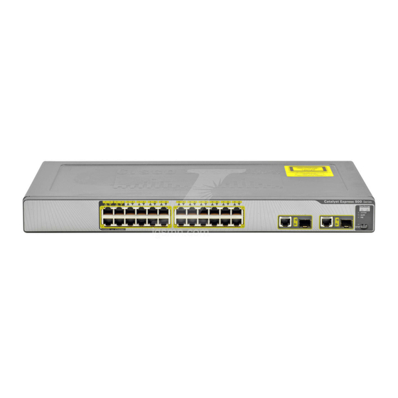
Page 19: Hardware Features
Figure 1-2 (PoE) ports supply up to Dual-purpose uplink ports: Autonegotiate and auto-MDIX OL-8122-01 and the list that follows describe the switch hardware features and the 2-5. Catalyst Express 500 Hardware Overview AC power connector Port LEDs Security cable slot... - Page 20 Port LEDs show port status. From the device manager GUI, port LEDs also show duplex mode, • speed, and PoE status. RPS LED shows status of an installed Cisco redundant power supply (RPS). (Available only on the • Catalyst Express 500-24PC model.) Setup Button •...
-
Page 21: Software Features
Monitoring • Alert LED notifies that one or more problems were detected on the switch. Alert Log lists all problems detected on the switch, including a timestamp of the most recent • detection of each problem. Graphical front panel display, LEDs, gauges, graphs, and animated indicators show switch and port •... -
Page 22: Device Manager Gui
• VLANs for grouping network users according to functions, teams, or applications, and regardless of the physical location of the network users. The switch supports up to 32 VLANs. VLAN support includes these features: Spanning Tree Protocol (STP) prevents network loops from developing and provides a –... - Page 23 Chapter 1 Introduction Features and Benefits Figure 1-3 Device Manager Interface User Guide for the Catalyst Express 500 Switches OL-8122-01...
-
Page 24: System Requirements
System Requirements Figure 1-4 System Requirements Hardware Requirements, page 1-11 • • Software Requirements, page 1-11 User Guide for the Catalyst Express 500 Switches 1-10 Device Manager Online Help Chapter 1 Introduction OL-8122-01... -
Page 25: Hardware Requirements
1. Service Pack 1 or higher is required for Internet Explorer 5.5. Switch Management Options In addition to the device manager GUI, you can also use these tools to manage the switch: Cisco Network Assistant, page 1-12 • Simple Network Management Protocol, page 1-13 •... -
Page 26: Cisco Network Assistant
Security configuration for all the Cisco access points in the network Interactive tools (such as wizards) to simplify configuration of complex • features For more information, see the Cisco Network Assistant Introduction at this URL: http://www.cisco.com/go/networkassistant User Guide for the Catalyst Express 500 Switches 1-12... -
Page 27: Simple Network Management Protocol
1000BASE-SX • When You Are Done If you have not already installed the switch and configured its basic settings, see Chapter 2, “Setup and Installation.” If you already installed and configured the switch with its basic settings, see Chapter 3, “Customization,”... - Page 28 Chapter 1 Introduction When You Are Done User Guide for the Catalyst Express 500 Switches 1-14 OL-8122-01...
-
Page 29: Setup And Installation
Setup and Installation Read this chapter to learn more about the switch setup and installation. This chapter also includes instructions on how to display the device manager in standard and in secure modes. Before You Begin Make sure that you have met the software and hardware requirements, as... -
Page 30: Chapter 2 Setup And Installation
Set Up the Switch for the First Time Prerequisite To set up the switch for the first time, follow the procedure described in the Getting Started Guide for the Catalyst Express 500 Switches. These are the configuration settings that you can set during initial setup: Network Settings, page 2-2 •... - Page 31 Note IP Address The IP address is a unique identifier for the switch in a network. The format is four numbers separated by periods. Each number can be from 0 to 255. This field is enabled only if the IP assignment mode is Static.
- Page 32 Password The password for the switch can have up to 25 alphanumeric characters, can start with a number, is case sensitive, and allows embedded spaces. The password cannot contain a ? or a tab and does not allow spaces at the beginning or end.
-
Page 33: Optional Settings
A name for the switch. The name can have up to 31 alphanumeric characters. The name cannot contain a ?, a space, or a tab. The default is Switch. We recommend entering either the name, location, or IP address of the switch to help identify the switch during monitoring or troubleshooting. -
Page 34: Warnings
Do not stack the chassis on any other equipment. If the chassis falls, it can cause severe bodily injury and equipment damage. Statement 48 Warning Attach only the Cisco RPS (model PWR675-AC-RPS-N1=) to the RPS receptacle. Statement 100C Warning Ethernet cables must be shielded when used in a central office environment. - Page 35 Statement 1017 Warning The plug-socket combination must be accessible at all times, because it serves as the main disconnecting device. Statement 1019 OL-8122-01 User Guide for the Catalyst Express 500 Switches Install the Switch...
- Page 36 Install the Switch This equipment must be grounded. Never defeat the ground conductor or Warning operate the equipment in the absence of a suitably installed ground conductor. Contact the appropriate electrical inspection authority or an electrician if you are uncertain that suitable grounding is available. Statement 1024...
-
Page 37: Installation Guidelines
Chapter 2 Setup and Installation Installation Guidelines When deciding where to place the switch, be sure to observe these requirements: Cabling is away from sources of electrical noise, such as radios, power lines, • and fluorescent lighting fixtures. Clearance to front and rear panels is such that •... -
Page 38: Rack-Mounting
OVER ETH ERN Insert the switch into the 19-inch rack, and align the bracket in the rack. Use either the 10-32 pan-head screws or the 12-24 pan-slotted screws to secure the switch in the rack. Use the supplied black Phillips machine screw to attach the cable guide to either bracket. -
Page 39: Desktop-Mounting
SYST Place the switch upside-down on a flat surface. Attach the four rubber pads to the recessed areas on the bottom of the switch. Place the switch on a desktop near an AC power source. If you are stacking switches, make sure that the mounting feet of the upper switch align with the recesses of the lower switch. -
Page 40: Wall-Mounting
Repeat on the opposite side. Mount the switch on the wall with the front panel facing up. For the best support of the switch and cables, make sure that the switch is attached securely to wall studs or to a firmly attached plywood mounting backboard. -
Page 41: Display The Device Manager
Use the device manager to perform basic switch configuration and monitoring. See the device manager online help for information. For more advanced configuration, download and run the Cisco Network Assistant (see the application. We recommend running the cryptographic software image on the switch and using the option to run a secured session with the switch. -
Page 42: When You Are Done
Chapter 2 Setup and Installation When You Are Done SSL is enabled by default on the switch. It is available only on the cryptographic version of the switch software image. More information about secured sessions is available from the device manager online help. -
Page 43: Customization
Customization Read this chapter to understand the concepts and tasks necessary to customize the switch features to better suit your network needs. The tasks in this chapter are independent, unless otherwise noted, and are listed in no particular order. Before You Begin Before you can customize the switch settings, the switch must first have an IP address. -
Page 44: Chapter 3 Customization
Use Smartports port roles immediately after switch initial setup. The switch ports are then correctly configured before they are connected to devices. The Smartports port roles are Cisco-recommended configurations for the switch ports. These configurations (referred to as port roles) optimize the switch connections and ensure security and transmission quality and reliability to traffic from the switch ports. - Page 45 A desktop device, such as a PC, can be connected to the IP phone. Both the IP phone and connected PC would have access to the network and the Internet through the switch port. This role prioritizes voice traffic over data traffic to ensure clear voice reception on the IP phones.
- Page 46 Optimize Ports through Smartports Port Roles Table 3-1 Smartports Port Roles (continued) Port Role Description Apply this role to ports that will be connected to desktop devices and to access points to provide guest wireless access. This role provides guests and visitors temporary access to the Internet but prevents them from accessing your internal network.
-
Page 47: Recommended Smartports Assignments
These assignments reflect the type of device connections intended for the switch model. If you decide to use most of the switch ports with their intended port roles, accept the recommended port roles, and change only the ports that need a different port role. -
Page 48: Avoid Smartports Mismatches
Avoid Smartports Mismatches A Smartports mismatch is when an attached device does not match the Smartports role applied to the switch port. Mismatches can have adverse effects on devices and your network. For example, mismatches Affect the behavior of the attached device •... -
Page 49: Customize Port Role Attributes
If the switch has only the default VLAN, ports applied with the Guest or IP Phone+Desktop port role can also belong to the default VLAN. However, if additional VLANs have been created: Ports applied with the Guest port role must belong to the Cisco-Guest VLAN. • •... -
Page 50: Change The Server Priorities
Customize Port Role Attributes Use the Smartports Customize window display this window, choose Configure > Smartports from the device manager menu, and then click the Customize button on the Smartports window. See the device manager online help for additional guidelines and procedures. Figure 3-3 Change the Server Priorities For ports applied with the Server port role, you can classify the priority of servers... -
Page 51: Update Basic Port Settings
This server type is for use with a voice-over-IP server. All traffic from this server type receives voice-quality priority as well as the same priority given to critical-type servers. An example of a trusted server is Cisco CallManager. Update Basic Port Settings The basic port settings determine how data is received and sent between the switch and the attached device. - Page 52 (autonegotiation) if the connected device can negotiate the link speed with the switch port. The default is Auto. We recommend using the default so that the speed setting on the switch port automatically matches the setting on the connected device. Change the switch port speed if the connected device requires a specific speed.
-
Page 53: Control Access To The Switch
Customization Whether PoE will be supplied to a connected device. Choose either: • Auto (automatically) to automatically provide power when an IEEE 802.af-compliant or Cisco pre-standard device is connected. • Never from the drop-down list. The default is Auto. Note This setting is available only on PoE ports. -
Page 54: Isolate Traffic And Users Through Vlans
These are the concepts and procedures for configuring VLANs: What Is a VLAN, page 3-12 • • VLAN Types, page 3-14 • Cisco-Guest and Cisco-Voice VLANs, page 3-16 Create, Modify, and Delete VLANs, page 3-16 • • Advanced VLAN Configuration, page 3-17 What Is a VLAN A virtual local area network (VLAN) is a logical segment of network users and resources grouped by function, team, or application. - Page 55 Devices attached to switch ports in different VLANs cannot communicate with each other through the switch. Inter-VLAN communication requires a router or Layer 3 switch. The router or Layer 3 switch must be configured to allow routing across VLANs (inter-VLAN routing), and additional security policies must be set.
-
Page 56: Vlan Types
Isolating data traffic from delay-sensitive traffic, such as voice traffic, ensures the quality of the voice transmission. In phones belong to the Cisco-Voice VLAN, a special VLAN supported on the switches. This VLAN automatically provides Voice over IP (VoIP) services on these connections, meaning priority is given to voice traffic over regular IP data traffic. - Page 57 VLAN. Both the switch port and the attached device port must be in the same native VLAN. A complete discussion about using VLANs is provided in Cisco LAN Switching Fundamentals published by Cisco Press. OL-8122-01...
-
Page 58: Cisco-Guest And Cisco-Voice Vlans
The VLAN names, Cisco-Guest and Cisco-Voice, are case sensitive. Note Only ports with the Guest port role can be assigned to the Cisco-Guest VLAN. Only ports with the IP Phone+Desktop port role can be assigned to the Cisco-Voice VLAN. -
Page 59: Advanced Vlan Configuration
Advanced VLAN Configuration The advanced VLAN options are the Spanning Tree Protocol (STP) and Internet Group Management Protocol (IGMP) snooping features on the switch ports. These options are enabled by default. We recommend that you leave these options enabled for the benefits that they provide: •... -
Page 60: Increase Connection Bandwidth Through Etherchannels
• IGMP snooping reduces duplicate and excess traffic on the network by forwarding IP multicast traffic to specific switch ports rather than by flooding all ports. With IGMP snooping, only ports that are members of specific IP multicast groups receive multicast messages. The result is a more efficient use of bandwidth. -
Page 61: What Is An Etherchannel
What Is an EtherChannel An EtherChannel (or port group) is a group of two or more Fast Ethernet or Gigabit Ethernet switch ports bundled into a single logical link, creating a higher bandwidth link between two switches. The switch supports up to six EtherChannels. -
Page 62: Create, Modify, And Delete An Etherchannel
• and its traffic is transferred to one of the remaining ports in the EtherChannel. All are applied with the Smartports Switch port role and belong to the same • VLAN. For information about port roles and VLAN memberships, see the “Optimize Ports through Smartports Port Roles”... -
Page 63: Update The Switch Ip Information
Existing settings were set during initial setup. You would need to change these settings if you want to move the switch to a different management VLAN or to a different network. Use the Express Setup window (Figure 3-11) to update the switch IP information. - Page 64 Figure 3-11 These are the switch network settings: Management The name and ID of the management VLAN through which the switch will be Interface (VLAN ID) managed. Select an existing VLAN to be the management VLAN. The default name for the management VLAN is default. The management VLAN ID was set during initial set up.
- Page 65 Configuration Protocol (DHCP) server. The default is Static. We recommend that you select Static and manually assign the IP address for the switch. You can then use the same IP address whenever you want to access the device manager. If you select DHCP, the DHCP server automatically assigns an IP address, subnet mask, and default gateway to the switch.
-
Page 66: Update Basic Administrative Settings
The Express Setup optional settings identify and synchronize the switch so that it can be managed properly. Existing settings might have been set during initial setup. Update these settings if you need to change the switch name or its system clock. -
Page 67: Enable The Switch For Remote Management
The agent also responds to manager commands to retrieve values from the MIB and to set values in the MIB. The agent and MIB are on the switch. To configure SNMP on the switch, you define the relationship between the manager and the agent. -
Page 68: Configuring Snmp
Configuring SNMP Enable SNMP if you plan to have the switch managed through another network management application. By default, SNMP is disabled. Other general SNMP settings include the name of the switch or the network administrator and the switch location. - Page 69 Chapter 3 Customization Community strings are forms of passwords to the switch Management Information Base (MIB). You can create community strings that allow a remote manager read-only or read-write access to the switch. The Read-Only community string operates as a password that enables the •...
-
Page 70: Supported Mibs
• • RMON-MIB (statistics, history, alarms, and events groups only) When You Are Done Monitor the performance of your network and the switch, as described in Chapter 4, “Monitoring.” User Guide for the Catalyst Express 500 Switches 3-28 Chapter 3... -
Page 71: Monitoring
Before You Begin: The monitoring features described in this chapter are available if the switch has an IP address. Make sure that the switch has been set up as described in the Getting Started Guide for the Catalyst Express 500 Switches. -
Page 72: Chapter 4 Monitoring
View a history of switch activity. • Check the Front Panel LEDs You can get a quick view of the overall condition of the switch by checking the device manager Front Panel view Figure 4-1 User Guide for the Catalyst Express 500 Switches (Figure 4-1). -
Page 73: System Leds
ALERT The presence of a switch problem. When the switch detects a problem on one or more ports, the Alert LED turns amber. Move the pointer over the Alert LED to display a description of the most recent problem detected, the port on which the problem exists, and the time that it was detected. The Alert LED stays amber until the Alert Log is cleared. -
Page 74: Port Leds
Check the Front Panel LEDs Port LEDs Choose an LED mode from the View list to change the type of information displayed through the port LEDs. Note that changing the modes of the LEDs is available only through the device manager. For the meanings of the port LED colors, see Table 4-2 STATUS... - Page 75 Chapter 4 Monitoring Figure 4-2 Table 4-3 Port LED Colors in Legend Port Mode Color Status Off (dark) Solid green Blinking green Solid brown Solid yellow Blinking green and amber Blinking amber Solid amber OL-8122-01 LED Legend Description No link. Link is up.
- Page 76 Port is disabled due to a fault condition. Description Switch is healthy. Switch is running POST. Switch is faulty, is rebooting, or is in recovery. No switch problem is detected. A switch problem is detected. PoE to the ports is off.
-
Page 77: Check The Status Field
The Status field (hardware issues and misconfigurations) on the switch. If no problems exist, the field shows that the overall switch operation is normal. This field is always visible during the device manager session. It is below the Front Panel view. -
Page 78: Check The Dashboard
Check the Dashboard View the Alert Log for the details of the problems and the most recent time at which the switch detected the problems. For information about the log, see the “Check the Alert Log” section on page Check the Dashboard The Dashboard and performance. -
Page 79: Switch Information
Serial Number The serial number of this switch. This information cannot be changed. Software The Cisco IOS software version that this switch is running. This information is updated when you upgrade the switch software. Contact The name of the person who is the administrative contact for this switch. This information is entered on the SNMP window or through Network Assistant. -
Page 80: Bandwidth Used Gauge
As you monitor utilization on the switch, note whether the percentage of usage is what you expect during that given time of network activity. If utilization is high when you expect it to be low, perhaps a problem exists. -
Page 81: Packet Error Gauge
The Port Statistics window displays some of the types of packet errors collected by the switch. The type of packet error can help you to identify a more precise cause for some network problems. For more information about port statistics, see the These are some types of packet errors. -
Page 82: Poe Gauge
The switch automatically maintains a power budget, monitors and tracks requests for power, and grants power only when it is available. If the switch is powering attached PoE devices, you should expect to see activity on this gauge. -
Page 83: Temperature Status
Bandwidth allocation can also be based on whether the connection is operating in half-duplex or full-duplex mode. Port Errors Graph—This graph displays the total percentage of errors on each • port. These are some of the reasons for errors received on and sent from the switch ports: – – –... -
Page 84: Check The Trends Graphs
If you are using the trends graphs to monitor the switch status over time, do not end your device manager session. Redisplaying the device manager clears the data from the PoE graph. -
Page 85: Bandwidth Utilization Graph
14 days). This graph also marks the highest peak reached. The default is 60 seconds. If you see sharp increases in switch usage, use this graph to determine when unusual peaks in network usage occur. For more information about bandwidth usage, see the “Bandwidth Used Gauge”... -
Page 86: Packet Error Graph
PoE Utilization Graph The PoE Utilization graph is only available if the switch is a PoE switch. This graph shows the same information as the PoE Utilization gauge on the Dashboard. The percentage of power allocated is shown over ten 60-second system refresh cycles. -
Page 87: Check The Port Status
VLAN. If the switch has link issues, such as traffic is not being received on a switch port, use this window to verify that the port settings are correct. You can check switch ports before connecting devices to the port to confirm that the settings of both devices match. -
Page 88: Check The Port Statistics
Check the Port Statistics Use the Port Statistics window to display the statistics for data sent from and received by the switch ports since the switch was last powered on, was restarted, or since the statistics were last cleared. The types of port statistics collected and displayed are grouped under these tabs... -
Page 89: Overview Tab
Chapter 4 Monitoring To display the Port Statistics window, choose Monitor > Port Statistics from the device manager menu. You also can click the View Port Statistics link from Dashboard. To clear the data from the statistics tables, click Clear Counters from the window. -
Page 90: Transmit Detail Tab
Check the Port Statistics devices. Any of these problems can cause slow network performance, data loss, or lack of connectivity. For example, to troubleshoot problems regarding loss of connectivity, clear the statistics for the port in question, and see if the port continues to receive and send packets. -
Page 91: Receive Detail Tab
Chapter 4 Monitoring Table 4-7 Transmit Detail Tab Descriptions Port The number of the port, including the port type (such as Fa for Fast Ethernet and Gi for Gigabit Ethernet) and the port number. Unicast packets The total number of well-formed unicast packets sent by a port. It excludes packets sent with errors or with multicast or broadcast destination addresses. - Page 92 Check the Port Statistics Table 4-8 Receive Detail Tab Descriptions Port The number of the port, including the port type (such as Fa for Fast Ethernet and Gi for Gigabit Ethernet) and the port number. Unicast packets The total number of well-formed unicast packets received by a port. It excludes packets received with errors, with multicast or broadcast destination addresses, or undersize packets, discarded packets, or those without a destination.
-
Page 93: Check The Alert Log
You can also click the Alert Log link in the popup when you move your pointer over the amber Alert LED. Use the Alert Log with the Alert LED on the Front Panel view. When the switch detects a problem, the Alert LED turns amber. -
Page 94: When You Are Done
Critical (2)—The switch has a critical condition. Error (3)—The switch has an error condition. Warning (4)—The switch has a warning condition. Notifications (5)—The switch is operating normally but has a significant condition. Description The description of the problem, including the ports on which the problem was detected. - Page 95 Before You Begin Familiarize yourself with the monitoring features (see from which you can find out the specific problems on the switch and from which you can prevent problems by addressing problematic trends. Chapter Topics •...
-
Page 96: Chapter 5 Troubleshooting
When the switch detects a problem, the Alert LED turns amber, and the Status field lists the detected problem. From the Diagnostics window can run switch and link diagnostic tests to solve the problems that the switch finds. The switch diagnostic test detects system and port problems on the switch. - Page 97 Figure 5-1 After running either or both tests, the window displays a report problems detected by the switch. The report also includes severity levels and recommended actions to help you solve the problems. The diagnostics report includes this information: Severity Level A single-digit code (0 to 5) that reflects the severity of the problem.
-
Page 98: Restart Or Reset The Switch
For example, if the problem exists after you reset the switch to its default settings, it is unlikely that the switch is causing the problem. -
Page 99: Restore Switch Settings
Upgrade the Switch Software Prerequisite You must have access to the Internet to download switch software from Cisco.com to your PC or network drive. Use the Software Upgrade window latest software changes (such as software patches) and features. To display this window, choose Software Upgrade from the device manager menu. - Page 100 When the upgrade process completes, a success message appears, and the switch automatically restarts. It might take a few minutes for the switch to restart with the new software. Check that the latest software version on the switch appears in the Software field in the Switch Information area of the Dashboard.
-
Page 101: Troubleshoot A Failed Software Upgrade
Chapter 5 Troubleshooting Troubleshoot a Failed Software Upgrade If the upgrade process does not complete or if the switch fails to restart after the upgrade process completes, follow these steps: Make sure that you downloaded the correct tar file from Cisco.com. -
Page 102: Recover A Password
Prerequisites • You must have physical access to the switch. Make sure that at least one switch port is enabled and is not connected to a • device. If you have lost or forgotten your username and password to the switch, follow these steps to delete all existing username-and-password pairs: Make sure that the SYSTEM LED is solid green. -
Page 103: Recover The Switch Software
Prerequisites • You must have physical access to the switch. Make sure that at least one switch port is enabled and is not connected to a • device. You might need to recover the switch software if the image is corrupted during an upgrade, if you installed the wrong image on the switch, or if you deleted the image. -
Page 104: Recover The Switch Software
The Software Recovery window appears Figure 5-4 From the Software Recovery window, you can choose: Erase system configuration Use this option to delete all the configuration settings on the switch, including the IP address, usernames, and passwords, but retain the software image. -
Page 105: When You Are Done
Flash image are deleted and the switch returns to using the factory default image. If you select this option, you must set up the switch again, as described in the Getting Started Guide for the Catalyst Express 500 Switches. - Page 106 Chapter 5 Troubleshooting When You Are Done User Guide for the Catalyst Express 500 Switches 5-12 OL-8122-01...
-
Page 107: Appendix
AC input voltage Catalyst Express 500-24TT: 100 to 240 VAC, 1.3–0.8 A (autoranging), 50 to 60 Hz Catalyst Express 500-24LC: 100 to 240 VAC, 2–1 A (autoranging), 50 to 60 Hz Catalyst Express 500-24PC: 100 to 240 VAC, 8–4 A (autoranging), 50 to 60 Hz Catalyst Express 500G-12TC: 100 to 240 VAC, 1.3–0.8 A (autoranging), 50 to 60 Hz... - Page 108 (IEEE 802.3af standard maximum) of power over Category 5 cable, for a total of 370 W of inline power. All 4 PoE ports on Catalyst Express 500-24LC switches can supply up to 15.4 W of power over Category 5 cable, for a total of 62 W of inline power.
-
Page 109: Cabling Guidelines
1.73 x 17.5 x 9.9 in. (4.39 x 44.45 x 25.15 cm) for Catalyst Express (H x W x D) 500-24TT, Catalyst Express 500-24LC, and Catalyst Express 500G-12TC 1.73 x 17.5 x 14.4 in. (4.39 x 44.45 x 36.58 cm) for Catalyst Express... - Page 110 Cabling Guidelines Table A-2 Fiber-Optic SFP Module Port Cabling Specifications Wavelength SFP Module (nanometers) 100BASE-BX-D 1550 TX 1310 RX 100BASE-BX-U 1310 TX 1550 RX 100BASE-FX Min.:1270 Typical: 1300 Max.: 1380 100BASE-LX 1310 1000BASE-LX 1300 1000BASE-SX 1. TX = send 2. RX = receive 3.
- Page 111 SX LC and SX LC-to-SC Multimode Fiber Patch Cables (SFP-to-SFP Connections) Type 10-meter, SX LC multimode fiber patchcord 10-meter, SX LC-to-SC multimode fiber patchcord OL-8122-01 Table A-3 Table A-5. Use the Cisco part Cisco Part Number CAB-CP-LCSC-2M CAB-CP-SCLC-8IN CAB-SMF-SC-10 CAB-SMF-SC-100 CAB-SMF-SC-25...
-
Page 112: Connector Specifications
Connector Specifications Connector Specifications This section describes the connectors used with the Catalyst Express 500 switches. 10/100 and 10/100/1000 Ports The Ethernet ports on the switches use standard RJ-45 connectors and Ethernet pinouts with internal crossovers Figure A-1 User Guide for the Catalyst Express 500 Switches (Figure A-1 10/100 Port Pinouts Label... -
Page 113: Sfp Module Ports
Appendix A Reference Figure A-2 SFP Module Ports The SFP module ports on switches use fiber-optic SFP modules with LC connectors a list of supported SFP modules. Figure A-3 OL-8122-01 10/100/1000 Port Pinouts Label TP0+ TP0- TP1+ TP2+ TP2- TP1- TP3+ TP3- (Figure... - Page 114 Appendix A Reference Connector Specifications User Guide for the Catalyst Express 500 Switches OL-8122-01...
-
Page 115: Appendix
Cisco Support Resources Read this chapter for Cisco support resources if you need assistance or further information about the switch. Before You Begin Use the diagnostic tools (Chapter 5, The other Catalyst Express 500 switch documents might also provide the information that you seek. -
Page 116: Support Links From The Device Manager Online Help
Support Links from the Device Manager Online Help Support Links from the Device Manager Online Help The device manager online help includes a Support window with links to Cisco support resources. To display this window, click Help from the device manager tool bar, and then click Support from the online help menu. -
Page 117: Cisco Networking Professionals Connection
Obtaining Documentation Cisco documentation and additional literature are available on Cisco.com. Cisco also provides several ways to obtain technical assistance and other technical resources. These sections explain how to obtain technical information from Cisco Systems. Cisco.com You can access the most current Cisco documentation at this URL: http://www.cisco.com/techsupport... -
Page 118: Product Documentation Dvd
Cisco products and to view technical documentation in HTML. With the DVD, you have access to the same documentation that is found on the Cisco website without being connected to the Internet. Certain products also have .pdf versions of the documentation available. -
Page 119: Documentation Feedback
• • Register to receive security information from Cisco. A current list of security advisories and notices for Cisco products is available at this URL: http://www.cisco.com/go/psirt If you prefer to see advisories and notices as they are updated in real time, you... -
Page 120: Reporting Security Problems In Cisco Products
Cisco is committed to delivering secure products. We test our products internally before we release them, and we strive to correct all vulnerabilities quickly. If you think that you might have identified a vulnerability in a Cisco product, contact PSIRT: •... -
Page 121: Obtaining Technical Assistance
SMB Support Assistant offers simple-to-use Portal and Client applications, 8 hours a day, 5 days a week TAC support, and Advanced Replacement Next Business Day. If you do not hold a valid Cisco service contract, please contact your reseller. SMB Support Assistant Portal and Client The Cisco SMB Support Assistant Portal and Client applications are management tools designed specifically for SMBs. -
Page 122: Submitting A Service Request
Cisco SMB Technical Assistance Center (Cisco SMB TAC). Requests can be submitted at any time, 24 hours a day, 365 days a year. A Cisco SMB TAC engineer will then respond to the request within 1 business day during normal business hours. - Page 123 You can access Packet magazine at this URL: http://www.cisco.com/packet • iQ Magazine is the quarterly publication from Cisco Systems designed to help growing companies learn how they can use technology to increase revenue, streamline their business, and expand services. The publication...
- Page 124 Appendix B Cisco Support Resources Obtaining Additional Publications and Information User Guide for the Catalyst Express 500 Switches B-10 OL-8122-01...
-
Page 125: I N D E X
Numerics 10/100/1000 ports See ports 10/100 ports See ports access control, customization access VLAN 3-15 acoustic noise A-13 AC power, specifications A-11 administrative settings, customization Alert LED features using Alert Log features using 4-23 Alert Log window displaying 4-23 using 4-23 OL-8122-01 altitude, operating... - Page 126 A-17 LC patch cables A-15 Cisco-Guest VLAN 3-7, 3-16 Cisco Network Assistant See Network Assistant Cisco Redundant Power Supply see RPS Cisco-Voice VLAN 3-7, 3-16 configuration file, restore settings connector specifications A-16 User Guide for the Catalyst Express 500 Switches...
-
Page 127: Cisco.com B
1-7, 5-2 report running switch test Diagnostics window displaying using dimensions, switch A-13 documentation additional sources B-3, B-8 cisco.com feedback networking basics ordering related products switch xiii dual-purpose uplink ports See ports duplex mode default 3-10 setting 3-10... - Page 128 Index EtherChannels benefits 3-19 creating 3-20 customization 3-18 deleting 3-20 features maximum number supported modes LACP 3-20 Static 3-20 modifying 3-20 overview 3-19 EtherChannels window displaying 3-20 using 3-21 Express Setup See initial setup Express Setup window displaying 3-21 using 3-22 fan status 4-12...
- Page 129 host name customization 3-24 default initial setup humidity, relative 2-9, A-12 IEEE 802.3ad (LACP) mode 3-20 IGMP snooping changing 3-17 features 1-8, 3-18 initial setup daylight saving time default gateway features host name IP address IP assignment mode management interface (VLAN ID) management VLAN network settings optional settings...
- Page 130 3-22 customization 3-22 default ID default name initial setup MIBs, supported 3-28 mismatch prevention, Smartports port roles models, switch recommended assignments (Smartports port roles) User Guide for the Catalyst Express 500 Switches IN-6 monitoring Alert Log 4-23 bandwidth used gauge...
- Page 131 system LEDs 4-3, 4-6 temperature status 4-13 trends bandwidth utilization 4-15 overview 4-14 packet error 4-16 per-port utilization and per-port error PoE utilization 4-16 why use 4-14 mounting desktop-mounting 2-11 rack-mounting 2-10 wall-mounting 2-12 mounting brackets See rack-mounting native VLAN 3-15 Network Assistant, features 1-12...
- Page 132 Index PoE gauge 4-12 PoE graph 4-16 PoE ports See PoE and ports pop-up blockers 1-11 port error graph 4-13 port LEDs 4-4, 4-5 port roles See Smartports port roles ports 10/100 cable lengths A-13 connecting to described pinouts A-16 recommended cables 10/100/1000 cable lengths...
- Page 133 2-10 procedure 2-10 recommended assignments, Smartports port roles requirements, system 1-10 hardware 1-11 software 1-11 reset switch Restart / Reset window displaying using restart switch restore settings features supported 1-13 OL-8122-01 safety warnings secured sessions See SSL...
- Page 134 See SNMP small form-factor pluggable modules See SFP modules Smartports Customize window displaying using Smartports port roles applying changing server priorities changing VLAN memberships Cisco-Guest VLAN Cisco-Voice VLAN customization optimize ports definitions features mismatch prevention overview recommended assignments Smartports window...
- Page 135 password recovery restart/reset software recovery software upgrade software recovery Software Recovery window displaying using 5-10 software upgrade cryptographic considerations troubleshooting Software Upgrade window displaying using Spanning Tree Protocol See STP specifications A-11 speed, setting 3-10 features using with device manager stacking switches 2-11 Static mode, EtherChannels...
- Page 136 See ports username customization initial setup 4-15 Users and Passwords window displaying using View list VLAN memberships changing Cisco-Guest VLAN Cisco-Voice VLAN prerequisite VLANs access VLAN advanced settings benefits Cisco-Guest Cisco-Voice creating 3-11 3-11 3-12 3-15...
- Page 137 VLANs 3-16 types of 3-14 VLANs Advanced window 3-18 displaying 3-18 using 3-18 VLANs window displaying 3-17 using 3-17 wall-mounting, procedure 2-12 warnings defined installation weight, switch A-12 OL-8122-01 3-16 User Guide for the Catalyst Express 500 Switches Index IN-13...
- Page 138 Index User Guide for the Catalyst Express 500 Switches IN-14 OL-8122-01...
Need help?
Do you have a question about the Catalyst Express 500-24LC and is the answer not in the manual?
Questions and answers