Table of Contents
Advertisement
Quick Links
Advertisement
Table of Contents

Related Manuals for Sunell Security SN-TPC4201VT


Summary of Contents for Sunell Security SN-TPC4201VT
- Page 1 Thermal Imaging Integrated Network Camera User Manual Issue V1.0 Date 2020-10-28...
- Page 3 Thermal Imaging Box Network Camera User Manual Precautions Precautions Precautions Fully understand this document before using this device, and strictly observe rules in this document when using this device. If you install this device in public places, provide the tip "You have entered the area of electronic surveillance" in an eye- catching place.
- Page 4 Thermal Imaging Box Network Camera Precautions User Manual ⚫ Strictly conform to local electrical safety standards and use power adapters that are marked with the LPS standard when installing and using this device. Otherwise, this device may be damaged. ⚫ Use accessories delivered with this device.
- Page 5 Thermal Imaging Box Network Camera User Manual Precautions ⚫ Use a soft and dry cloth to clean the device body. In case that the dirt is hard to remove, use a dry cloth dipped in a small amount of mild detergent and gently wipe the device, and then dry it again.
-
Page 6: Table Of Contents
Thermal Imaging Box Network Camera Contents User Manual Contents 1 Product Overview ....................1 1.1 Thermal Imaging Principles and Advantages ..............1 1.2 Device Structure ......................1 1.3 Functions and Features ....................5 2 Quick Configuration ....................6 2.1 Login and Logout ......................6 2.2 Main Page layout ...................... - Page 7 Thermal Imaging Box Network Camera User Manual Contents A Troubleshooting....................47 B Common Emission Rate ..................49 Issue V1.0 (2020-10-28)...
-
Page 9: Product Overview
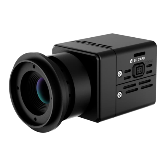
Thermal Imaging Box Network Camera Product Overview User Manual Product Overview 1.1 Thermal Imaging Principles and Advantages For any object, as long as its temperature is above the absolute zero (-273.15°C), although the object does not give out light, it can radiate infrared. The infrared is also known as thermal radiation. - Page 10 Thermal Imaging Box Network Camera Product Overview User Manual Figure 1-1 Appearance and interfaces of device Issue V1.0 (2020-10-28)...
- Page 11 Thermal Imaging Box Network Camera Product Overview User Manual Figure 1-2 Port of device Issue V1.0 (2020-10-28)...
- Page 12 Thermal Imaging Box Network Camera Product Overview User Manual Table 1-1 Interfaces Char Physical Interface Connection Audio input/audio Inputs the audio signal and receives the analog output audio signals from the sound pick-up device. Audio Connects to the external alarm out device, such as alarm light.
-
Page 13: Functions And Features
Thermal Imaging Box Network Camera Product Overview User Manual Char Physical Interface Connection Network interface Connects to the standard Ethernet cable. DC 12V Power interface Connects to the 12 V DC power supply. Ground SD card slot Plug the SD card to save the video recording. CARD Zoom port Connect to zoom control cable of motorized... -
Page 14: Quick Configuration
Thermal Imaging Box Network Camera Quick Configuration User Manual Quick Configuration 2.1 Login and Logout You must use Internet Explorer 8 or a later version to access the web management system; otherwise, some functions may be unavailable. Login system Step 1 Open the Internet Explorer, enter the IP address of IP camera (default value: 192.168.0.121) in the address box, and press Enter. -
Page 15: Main
Thermal Imaging Box Network Camera Quick Configuration User Manual ⚫ The default name and password are both admin. Modify the password when you login the system for first time to ensure system security. After modifying password, you need to wait at least three minutes then power off to make sure modifying successfully . Or login the Web again to test the new password. - Page 16 Thermal Imaging Box Network Camera Quick Configuration User Manual Figure 2-2 Main page layout 7 8 9 10 11 12 13 Table 2-1 Elements on the main page Element Description Real-time video Real-time videos are played in this area. You can also set area sensor parameters.
-
Page 17: Change The Password
Thermal Imaging Box Network Camera Quick Configuration User Manual Element Description Stream Three are three streams. Choose one type from drop-down list. Pause/Start Close live video or play live video. Live/Smooth Switch image quality. Audio Open or close audio. Interphone Open or close interphone. -
Page 18: Browse Video
Thermal Imaging Box Network Camera Quick Configuration User Manual Figure 2-3 Modify Password dialog box The change password page will be displayed if you don’t change the default password when you login the system for the first time. User need to wait at least three minutes after changing password, and then restart the device. - Page 19 Thermal Imaging Box Network Camera Quick Configuration User Manual In the display dialog box, click Add, as shown in Figure 2-4. Figure 2-4 Add the a trusted site Step 2 In the Internet Explorer, choose Tool > Internet Options > Security > Customer level, and set Download unsigned ActiveX control and initialize and script ActiveX controls not marked as safe for scripting under ActiveX controls and plug-ins to Enable, as shown in Figure 2-5.
-
Page 20: Install Plugins
Thermal Imaging Box Network Camera Quick Configuration User Manual The login page is display when the control is loaded. 2.4.1 Install Plugins You will be prompted with a message “Download and install the new plugin” will show as in Figure 2-6, when you login to the web management system for the first time. Figure 2-6 Install plugin Procedure Step 1... - Page 21 Thermal Imaging Box Network Camera Quick Configuration User Manual Figure 2-7 Local Network page Step 2 Set the parameters according to Table 2-2. Table 2-2 Local network parameters Parameter Description Setting IP Protocol IPv 4 is the IP protocol that uses [Setting method] an address length of 32 bits.
- Page 22 Thermal Imaging Box Network Camera Quick Configuration User Manual Parameter Description Setting IP Address Device IP address that can be [Setting method] set as required. Enter a value manually. [Default value] 192.168.0.121 Subnet Mask Subnet mask of the network [Setting method] adapter.
- Page 23 Thermal Imaging Box Network Camera Quick Configuration User Manual ⚫ If you set only the Subnet Mask, Default Gateway, Preferred DNS Server, and Alternate DNS Server parameters, you do not need to login to the system again. ⚫ You can click Reset to set the parameters again if required. ----End Issue V1.0 (2020-10-28)...
-
Page 24: Thermal Setting
Thermal Imaging Box Network Camera Thermal Setting User Manual Thermal Setting 3.1 Temperature Parameters Temperature parameters include temperature unit, ambient type, ambient temperature, cavity temperature, correctional coefficient, area temperature display mode, area temperature type, measure mode, and area alarm interval. Operation Procedure Step 1 Choose Configuration >Thermal >Temperature Parameters. - Page 25 Thermal Imaging Box Network Camera Thermal Setting User Manual Figure 3-1 Temperature Parameters interface Step 2 Set the parameters according to Table 3-1. Table 3-1 Temperature parameters Parameter Description Setting Temperature Unit Celsius and Fahrenheit [Setting method] temperature units are available. Select a value from the drop-down list box.
- Page 26 Thermal Imaging Box Network Camera Thermal Setting User Manual Parameter Description Setting Correction Correction coefficient is refer to [Setting method] Coefficient the deviation of measured Enter a value manually. object temperature and [Default value] actual temperature, is offset 0.00 value. For example: 1.
- Page 27 Thermal Imaging Box Network Camera Thermal Setting User Manual Parameter Description Setting Measure Mode There are two types of measure [Setting method] modes. Select a value from the drop-down list box. [Default value] General Display Alarm [Setting method] Area Enable or disable [Default value] Disable Area Alarm...
- Page 28 Thermal Imaging Box Network Camera Thermal Setting User Manual Figure 3-2 Advanced interface Table 3-2 Advance parameters Parameter Description Setting Dimming Mode There are auto and manual [Setting method] modes. It will show on Select a value from the temperature item. drop-down list box.
-
Page 29: Ambient Temperature
Thermal Imaging Box Network Camera Thermal Setting User Manual Parameter Description Setting Raw Data Upload Interval of Uploading the raw [Setting method] Interval(F/S) data. Select a value from the drop-down list box. [Default value] Mix Stream Mode This function is used for [Default value] thermal and visible image to Close... -
Page 30: Temperature Area
Thermal Imaging Box Network Camera Thermal Setting User Manual 3.3 Temperature Area Operation Procedure Step 1 Choose Configuration >Thermal >Temperature Area. The Temperature Area page is displayed, as shown in Figure 3-3. Figure 3-3 Temperature area and alarm configuration Step 2 Set the parameters according to Table 3-4. - Page 31 Thermal Imaging Box Network Camera Thermal Setting User Manual Table 3-4 Temperature area and alarm configuration Parameter Description Setting Channel [Setting method] Select a value from the drop-down list box. [Default value] Measure Mode Set at temperature parameter interface. Name Area name of temperature area.
- Page 32 Thermal Imaging Box Network Camera Thermal Setting User Manual Parameter Description Setting Emission Rate The emission rate is the [Setting method] capability of an object to emit Enter a value manually. or absorb energy. [Default value] The emission rate should be set 0.95 only when the target is special material.
- Page 33 Thermal Imaging Box Network Camera Thermal Setting User Manual Parameter Description Setting Group ID The ID can be chosen into one [Setting method] of six groups, or no group. The Select a value from the group will be alarm following drop-down list box.
- Page 34 Thermal Imaging Box Network Camera Thermal Setting User Manual Figure 3-4 Temperature Area Setting Interface Step 3. Click Apply, the message “Apply success” is displayed, the temperature area is set successfully. NOTE ID 0 is the full screen, the area cannot be changed. : the lowest temperature of the full screen.
-
Page 35: Shield Area
Thermal Imaging Box Network Camera Thermal Setting User Manual ----End 3.4 Shield Area Shield area is meaning that the camera will do not detect the temperature of that area. The shield areas can be set up to four areas. Operation Procedure Step 1 Choose Configuration >Thermal >... - Page 36 Thermal Imaging Box Network Camera Thermal Setting User Manual The Schedule Linkage page is displayed, as shown in Figure 3-6. Tick the output channel if user connects the external alarm device. It can also enable alarm record, SMTP, FTP upload and audio alarm. Figure 3-6 Schedule Linkage Step 2 Tick the output channel.
- Page 37 Thermal Imaging Box Network Camera Thermal Setting User Manual Figure 3-7 Sound alarm output User can set the audio file manually. Click to upload the audio file(the type should be WAV), as shown in Figure 3-8. Figure 3-8 Upload audio file Step 3 Set schedule linkage.
-
Page 38: Bad Point Check
Thermal Imaging Box Network Camera Thermal Setting User Manual When you select time by dragging the cursor, the cursor cannot be moved out of the time area. Otherwise, no time can be selected. Method 3:Click in the alarm time page to select the whole day or whole week. Deleting alarm time: Click again or inverse selection to delete the selected alarm time. - Page 39 Thermal Imaging Box Network Camera Thermal Setting User Manual Figure 3-9 Bad Point Check Step 2 Click the white point at image, click Test to recover the bad point, as shown in Figure 3-10 Issue V1.0 (2020-10-28)...
-
Page 40: Version Information
Thermal Imaging Box Network Camera Thermal Setting User Manual Figure 3-10 Recover bad point Step 3 Click Apply. The message "Apply success" is displayed, the system saves the settings. ----End 3.7 Version Information Choose Configuration >Thermal > Version Information. User can view the version information as shown in Figure 3-11. -
Page 41: Parameter Setting
Thermal Imaging Box Network Camera Parameter Setting User Manual Parameter Setting 4.1 Sensor Setting Interface Operation Procedure Step 1 On the Internet Explorer interface or the client software interface, select and right-click the surveillance image to the set, as shown in Figure 4-1. Figure 4-1 Sensor Setting Table 4-1 Right-click setting parameters Parameter... -
Page 42: Mode Setting
Thermal Imaging Box Network Camera Parameter Setting User Manual Step 2 Choose Sensor. The Sensor Configuration dialog box is displayed, as shown in Figure 4-2. ----End 4.2 Mode Setting Figure 4-2 shows the time segment interface. Figure 4-2 Time segment interface Operation Procedure Step 1 Click... -
Page 43: Scene
Thermal Imaging Box Network Camera Parameter Setting User Manual Figure 4-3 Image interface Table 4-2 lists the image setting parameters. Table 4-2 Image setting parameters Parameter Description Setting Brightness It indicates the total brightness of an image. As [Setting the value increases, the image becomes brighter. method] Drag the slider. -
Page 44: Set Pseud Ocolor
Thermal Imaging Box Network Camera Parameter Setting User Manual Figure 4-4 Scene interface Provide the selection of image pixel locations. Normal: the image is not flipped. Horizontal: the image is flipped left and right. Vertical: the image is flipped up and down. Horizontal + Vertical: the image upside-down and reversal. -
Page 45: Ffc Control
Thermal Imaging Box Network Camera Parameter Setting User Manual ranging from 0 to 255. Different polarity modes can be converted to different display images. The most common setting is white hot (a hotter object is displayed brighter than a colder object) or black hot (a hotter object is displayed darker than a colder object). - Page 46 Thermal Imaging Box Network Camera Parameter Setting User Manual Parameter Description Setting of the sensor can collect uniform temperature fields (flat field). By means of FFC, the camera can update the correction coefficients to output more uniform images. Throughout the FFC process, the video image is frozen for two seconds and a static-frame image is displayed.
-
Page 47: Noise Reduction
Thermal Imaging Box Network Camera Parameter Setting User Manual Parameter Description Setting Adjust Click the icon and adjust the image by covering Background the camera’s lens, finish the image adjustment by Adjust removing the shelter. ----End 4.7 Noise Reduction Figure 4-7 shows the Noise Reduction interface. Figure 4-7 Noise reduction interface Table 4-4 lists the Noise reduction parameters. -
Page 48: Enhance Image
Thermal Imaging Box Network Camera Parameter Setting User Manual Parameter Description Setting Auto ----End 4.8 Enhance Image Figure 4-8 shows the Enhance Image interface. Figure 4-8 Enhance image interface Tick defog, and drag the slider to adjust. The default value is 50. ----End 4.9 Lens Control The lens control is useful for motorized lens, please refer to actual products. - Page 49 Thermal Imaging Box Network Camera Parameter Setting User Manual Figure 4-9 Lens control interface Click the to do near focus/ far focus. Click to do auto focus, the focusing charter will show on live video. Click to initialize the lens. ----End Issue V1.0 (2020-10-28)...
-
Page 50: Technical Specifications
Thermal Imaging Box Network Camera Technical Specifications User Manual Technical Specifications Table 5-1 lists the specifications of the thermal imaging box camera. Table 5-1 Technical specifications Type Parameter Description Detector type Uncooled infrared focal plane sensor Sensing mode Micro bolometer Pixel 400x300 Detector... - Page 51 Thermal Imaging Box Network Camera Technical Specifications User Manual Type Parameter Description Black hot / white hot / rainbow / iron Polarity LUT bow (up to 17define optional) 2D/3D Contrast Support Imaging Horizontal, Vertical, Horizontal + features Mirror Vertical Outdoor, Indoor, Sky/Earth, Sea/Sky, Screen interface mode Linear, Common, Custom OSD display...
- Page 52 Thermal Imaging Box Network Camera Technical Specifications User Manual Type Parameter Description accuracy temperature, etc.) Multiple temperature area Support. Temperature response Less than 30 millisecond time Effective range of working -30℃~+60℃ temperature Temperature range -20℃~+150℃ IPv4/IPv6, RTSP/RTP/RTCP, TCP/UDP, HTTP, DHCP, DNS, Network protocol FTP, DDNS, PPPOE, SMTP, and Heartbeat mechanism...
- Page 53 Thermal Imaging Box Network Camera Technical Specifications User Manual Type Parameter Description features Defog Support Time segment Support IO alarm detection Support Privacy mask 5 areas with configurable size Temperature, time, date, channel Character display name and user-defined characters. Password protection, multi-level user group management, user-define Security permissions, and one-key reset.
- Page 54 Thermal Imaging Box Network Camera Technical Specifications User Manual Type Parameter Description Weight About 300 g (no lens) Issue V1.0 (2020-10-28)...
- Page 55 Thermal Imaging Box Network Camera A Troubleshooting User Manual Troubleshooting Common Possible Cause Solution Trouble ⚫ Unable to Network is not Connect the network cable of the camera to access the connected. the PC to check whether the network cable is in good contact.
- Page 56 Thermal Imaging Box Network Camera A Troubleshooting User Manual Common Possible Cause Solution Trouble An error The data in the Delete the cache of the Internet Explorer. The occurs in cache of browser is steps are as follows (taking IE9 as an example): accessing not updated in time.
- Page 57 Thermal Imaging Box Network Camera B Common Emission Rate User Manual Common Emission Rate Emission Rate The emission rate is the capability of an object to emit or absorb energy. An ideal transmitter provides an emission rate of emitting 100% of intake energy. An object with an emission rate of 0.8 can absorb 80% of intake energy, and reflect the remaining 20%.
- Page 58 Thermal Imaging Box Network Camera B Common Emission Rate User Manual Lead (99.9% purity, No 127/260 0.06 oxidized) Copper 0.18 Cobalt 599/111 0.19 199/390 0.52 Steel 599/1110 0.57 Tinned iron sheet (Light) 28/82 0.23 Brass(High-polish) 247/476 0.03 Brass (Tough rolled, polished 21/70 0.04 metal wire)
- Page 59 Thermal Imaging Box Network Camera B Common Emission Rate User Manual Brick (Red, rough) 21/70 0.93 Brick (Unglazed, rough) 1000/1832 Carbon (T - carbon 0.9% ash) 127/260 0.81 Concrete 0.94 Glass (Glossy) 22/72 0.94 Granite (Surfaced) 21/70 0.85 0/32 0.97 Marble (I Polished, grey) 22/72 0.93...
Need help?
Do you have a question about the SN-TPC4201VT and is the answer not in the manual?
Questions and answers