Advertisement
Quick Links
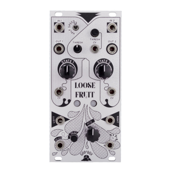
God's Box – Loose Fruit
Eurorack DIY Kit
Version 1.1
Instructions
OVERVIEW
For the most recent version of this
document please visit
https://www.thonk.co.uk/documents/gbox
This document has hi-res images. ZOOM
IN for a closer look
All
Thonk kits are sold under our standard Terms and Conditions -
http://www.thonk.co.uk/faq/
DIY INSTRUCTIONS
This document gives detailed instructions that assume you have purchased a
complete kit from www.thonk.co.uk. It also assumes no previous knowledge
of electronics. To learn to solder try
http://youtu.be/I_NU2ruzyc4
and the
Adafruit guide to excellent soldering –
http://bit.ly/1l77tF4
Watch and understand that whole YouTube video! If you're not achieving the
results shown in the video then you need to buy new tools or seek advice.
You will not end up with a working module otherwise.
TOOLS REQUIRED
Soldering iron, snipe nose pliers, wire strippers, small flat head screwdriver
and diagonal cutters AKA snips AKA side-cutters. A Digital Multimeter is
always helpful for checking for bad solder joints and continuity. Thonk sell a
range of inexpensive tools here -
http://bit.ly/1jxqF3n
Jan 9th 2019
www.thonk.co.uk
1
Advertisement

Related Manuals for Thonk Loose Fruit


Summary of Contents for Thonk Loose Fruit
- Page 1 Soldering iron, snipe nose pliers, wire strippers, small flat head screwdriver and diagonal cutters AKA snips AKA side-cutters. A Digital Multimeter is always helpful for checking for bad solder joints and continuity. Thonk sell a range of inexpensive tools here - http://bit.ly/1jxqF3n...
-
Page 2: Solder Joints
God’s Box – Loose Fruit Eurorack DIY Kit Version 1.1 Instructions SOLDER JOINTS Your solder joints should look like those shown as ‘OK’ below, they should have that neat conical shape on BOTH sides of the PCB. If they don’t look the same on both sides then stop! Work out why from the soldering guides linked and don’t continue until you are getting those results. - Page 3 God’s Box – Loose Fruit Eurorack DIY Kit Version 1.1 Instructions LOOSE FRUIT BUILD INSTRUCTIONS There are two PCBs used in this build - they are referred to as the top board and the bottom board. They can be identified by locating the text on each PCB as shown.
- Page 4 God’s Box – Loose Fruit Eurorack DIY Kit Version 1.1 Instructions Next solder in the six 1N4148 diodes. These are labelled on the PCB as: ’48 Do not confuse these with the zener diodes which are also coloured orange and black.
- Page 5 God’s Box – Loose Fruit Eurorack DIY Kit Version 1.1 Instructions Now take the top board and solder the two 150pF ceramic capacitors. Now move to the bottom board and solder the three 22pF ceramic capacitors. Next solder four 470pF ceramic capacitors.
- Page 6 God’s Box – Loose Fruit Eurorack DIY Kit Version 1.1 Instructions Next solder in the IC sockets on both PCBs. Make sure these sockets are soldered flush and perpendicular to the PCB surface. The notch on each socket should match the PCB silkscreen as shown in the pictures.
- Page 7 God’s Box – Loose Fruit Eurorack DIY Kit Version 1.1 Instructions Next solder in the double standing ferrite bead. Orientation does not matter for this part. Bottom Board Next take one of the 2x5 male headers and one of the 2x3 male headers.
- Page 8 God’s Box – Loose Fruit Eurorack DIY Kit Version 1.1 Instructions Next solder four 22uF Electrolytic Capacitors - there are two on each PCB. NOTE! Orientation is vital on this part. The grey stripe and shorter leg signify the negative side of the...
- Page 9 God’s Box – Loose Fruit Eurorack DIY Kit Version 1.1 Instructions Now solder the two J105 JFETs as shown. NOTE! Orientation matters – be sure to match the curve of the body to the PCB silkscreen. Bottom Board Next place...
- Page 10 God’s Box – Loose Fruit Eurorack DIY Kit Version 1.1 Instructions TL052 V2164D Firmware Now disconnect the PCBs and fit TL072 all the ICs into their sockets as shown. TL052 NOTE! Orientation is vital for all ICs For the TL052 and TL072 ICs make...
- Page 11 God’s Box – Loose Fruit Eurorack DIY Kit Version 1.1 Instructions SWITCH NUT SHORT TALL Next place but DO NOT SOLDER the pots, jacks and switch. Screw just one of the hex nuts onto the switch - do not use the switch washer.
- Page 12 The red stripe should always be facing the PCB text label ‘RED’ The module is now complete. No calibration is required for the Loose Fruit More info on God’s Box modules can be found at http://godsbox.co.uk Jan 9th 2019 www.thonk.co.uk...
Need help?
Do you have a question about the Loose Fruit and is the answer not in the manual?
Questions and answers