Table of Contents
Advertisement
Quick Links
Advertisement
Table of Contents

Related Manuals for ARDESTO ACM-09CRN7


Summary of Contents for ARDESTO ACM-09CRN7
- Page 2 Дякуємо за придбання нашого мобільного кондиціонера. Перед використанням кондиціонера уважно прочитайте цей посібник та зберігайте його для подальшого використання. ПРОЧИТАЙТЕ І ЗБЕРІГАЙТЕ ЦЕЙ ПОСІБНИК! З МІСТ Підготовка ......................... Заходи безпеки......................... Застереження ........................Встановлення ......................... Робота ..........................Технічне обслуговування ..................... Діагностика...
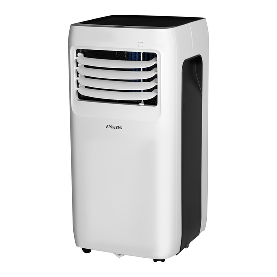
- Page 3 П ІДГОТОВКА Вигляд спереду Вигляд ззаду...
- Page 4 ПІДГОТОВКА ПРИМІТКА. Придбаний пристрій може виглядати наступним чином:...
- Page 5 З АХОДИ БЕЗПЕКИ Цей символ вказує на те, що недотримання інструкції може призвести до смерті або важкої травми. ПОПЕРЕДЖЕННЯ. Дотримуйтеся цієї інструкції для запобігання смертельних випадків, травмування або пошкодження майна. Неправильна експлуатація приладу через недотримання цієї інструкції може призвести його власника та інших людей до смертельної загрози...
- Page 6 З АСТЕРЕЖЕННЯ Застереження Цей прилад може використовуватися дітьми у віці не менше 8 років і особами з обмеженими фізичними, сенсорними або розумовими можливостями, а також особами без достатнього досвіду та знань, за умови нагляду або надання їм вказівок щодо безпечного користування пристроєм та пояснення небезпек, пов'язаних з йог о використанням.
- Page 16 В СТАНОВЛЕННЯ Правильний вибір місця розташування Місце розташування має відповідати наступним вимогам: Щоб мінімізувати шум та вібрацію, пристрій необхідно встановлювати на рівну поверхню. Встановлюйте пристрій поблизу заземленої розетки та забезпечте вільний доступ до лотка для зливу води (ззаду пристрою). Щоб забезпечити належне кондиціонування повітря, пристрій повинен знаходитися на відстані...
- Page 17 Пилка (опціонально, для скорочення віконного перехідника для вузьких вікон). Приладдя Ваш комплект призначений для встановлення у вікна розміром 67,5-123 см або для менших вікон. Перелік приладдя, що може постачатися разом з мобільним кондиціонером, вказано в таблиці нижче. Деталь Опис Кількість Перехідник...
- Page 18 2. Якщо довжина вікна вимагає встановлення двох ковзких елементів, за допомогою гвинта скріпіть ковзкі елементи віконної засувки для досягнення відповідної довжини. Гвинт Ковзкий елемент віконної засувки А Ковзкий елемент віконної засувки В Примітка. Після підготовки випускного рукава та регульованої віконної засувки, виберіть один з...
- Page 19 4) При необхідності, встановіть кронштейн кріплення за допомогою 2 гвинтів, як показано на малюнку 5) Вставте перехідник віконної засувки в отвір віконної засувки. Варіант 2: Встановлення у розсувне вікно (за вибором) 1) Виріжте з клейкого ущільнювача стрічки А і В необхідної...
- Page 20 3) Виріжте з неклейкого губчастого ущільнювача стрічку С необхідної довжини. Всуньте стрічку губчастого ущільнювача між склом та віконною рамою, щоб запобігти потраплянню в кімнату повітря та комах. 4) При необхідності, встановіть кронштейн кріплення за допомогою 2 гвинтів, як показано на малюнку.
- Page 21 Примітка. Якщо отвір не використовується, закрийте його кришкою перехідника. Примітка. Для забезпечення належного функціонування, НЕ витягуйте та не згинайте рукав. Для правильної роботи випускної системи перевірте, щоб навколо отвору випускного рукава (на відстані 500 мм) не було перешкод. Всі ілюстрації в цьому посібнику призначені лише для пояснення. Ваш кондиціонер може дещо...
- Page 22 ПРИМІТКА. На панелі управління відображається температура в градусах за Фаренгейтом або в градусах за Цельсієм. Для переходу з одних значень на інші натисніть одночасно та тримайте протягом 3 секунд кнопки «Вгору та Вниз». Кнопка увімкнення живлення Цією кнопкою вмикається або вимикається живлення. Світлодіодний...
- Page 23 - Натисніть на кнопку ШВИДКІСТЬ ВЕНТИЛЯТОРА на пульті дистанційного керування та налаштуйте швидкість вентилятора. Температуру в цьому режимі не можна налаштувати. - Не вставляйте рукав у вікно. Інші особливості Режим СОН / ЕКО (SLEEP / ECO) Цю функцію можна активувати лише з пульта дистанційного керування. При активації функції СОН, задана...
- Page 24 ФУНКЦІЯ РЕГУЛЮВАННЯ ПОТУЖНОСТІ (за вибором) Якщо температура навколишнього середовища буде нижче встановленої температури протягом певного періоду часу, пристрій буде автоматично регулювати живлення. Двигун компресора та вентилятора припинить свою роботу. Коли температура навколишнього середовища буде вище встановленої температури, пристрій автоматично вийде з функції керування...
- Page 25 кондиціювання / осушення. Однак двигун вентилятора продовжуватиме працювати (це нормально). Обережно перемістіть пристрій у місце зливу, зніміть нижню дренажну заглушку та злийте воду. Встановіть на місце заглушку нижнього отвору для зливу води та перезапустіть пристрій. Позначка «P1» повинна зникнути. Якщо помилка буде повторюватися, зателефонуйте...
- Page 26 - Вимкніть прилад та відключіть його від мережі. - Очистіть повітряний фільтр відповідно до інструкцій, наведених у попередньому розділі. Перед зберіганням перевстановіть чистий та сухий фільтр. - Вийміть батарейки з пульта дистанційного керування. Обов'язково зберігайте пристрій у прохолодному темному місці. Вплив прямого сонячного...
- Page 27 Енергетичні параметри даного пристрою ґрунтуються на установці з використанням не подовженого випускного рукава без перехідника віконної засувки або перехідника «А» для настінної витяжки (як показано в розділі «Встановлення» цього посібника). Поряд з цим пристрій повинен налаштовуватися у режимі ОХОЛОДЖЕННЯ та ВИСОКА ШВИДКІСТЬ ВЕНТИЛЯТОРА...
-
Page 28: Table Of Contents
CONTENTS Handling the remote controller ............Remote controller Specifications........... Function buttons ................Indicators on LCD ................How to use the buttons ..............Auto operation................. Cooling/Heating/Fan operation............Dehumidifying operation ............... Adjusting air flow direction............Timer operation................ - Page 38 Contents S a f e t y P r e c a u t i o n s - - - - - - - - - - - - - C a u t i o n s - - - - - - - - - - - - - - - - - - - W a r n i n g s - - - - - ( f o r u s i n g R 2 9 0 / R 3 2 r e f r i g e r a n t o n l y )
- Page 39 Safety Precautions Safety Precautions This symbol indicates that ignoring instructions may cause death or serious injury. Read Safety Precautions Before Operation and Installation WARNING: To prevent death or injury to the user or other people and property damage, To prevent death or injury to the user or other people and property damage, the the following instructions must be followed.
- Page 40 Cautions Cautions In a thunderstorm, the power must be cut off to avoid damage to the machine due to lightning. • -This appliance can be used by children aged from 8 years and above and person with Your air conditioner should be used in such a way that it is protected from moisture. •...
- Page 41 Disconnect the power if strange sounds, smell, or smoke comes from it. • Do not press the buttons on the control panel with anything other than your fingers. • • Do not remove any fixed covers. Never use this appliance if it is not working properly, or if it has been dropped or damaged.
-
Page 42: S A F E T Y P R E C A U T I O N S
WARNING for Using R32/R290 Refrigerant Do not use means to accelerate the defrosting process or to clean, other than those recommended by the manufacturer. The appliance shall be stored in a room without continuously operating ignition sources (for example: open flames, an operating gas appliance or an operating electric heater). Do not pierce or burn. - Page 43 1.Transport of equipment containing flammable refrigerants See transport regulations 2.Marking of equipment using signs See local regulations 3.Disposal of equipment using flammable refrigerants See national regulations. 4.Storage of equipment/appliances The storage of equipment should be in accordance with the manufacturer's instructions. 5.Storage of packed (unsold) equipment Storage package protection should be constructed such that mechanical damage to the equipment inside the package will not cause a leak of the refrigerant charge.
- Page 44 8)Checks to the refrigeration equipment Where electrical components are being changed, they shall be fit for the purpose and to the correct specification. At all times the manufacturer's maintenance and service guidelines shall be followed. If in doubt consult the manufacturer's technical department for assistance. The following checks shall be applied to installations using flammable refrigerants: The charge size is in accordance with the room size within which the refrigerant containing parts are installed;...
- Page 45 9.Cabling Check that cabling will not be subject to wear, corrosion, excessive pressure, vibration, sharp edges or any other adverse environmental effects. The check shall also take into account the effects of aging or continual vibration from sources such as compressors or fans. 10.Detection of flammable refrigerants Under no circumstances shall potential sources of ignition be used in the searching for or detection of refrigerant leaks.
- Page 46 14.Decommissioning Before carrying out this procedure, it is essential that the technician is completely familiar with the equipment and all its detail. It is recommended good practice that all refrigerants are recovered safely. Prior to the task being carried out, an oil and refrigerant sample shall be taken in case analysis is required prior to re-use of reclaimed refrigerant.
- Page 47 Preparation control panel handle horizontal louver control (both sides) lever(adjust manually) air filter NOTE: PHA can not be adjusted. (behind the grille) vertical louver control upper air intake lever(adjust manually) NOTE: PHA can not be adjusted. drain outlet air outlet panel lower air intake bottom tray...
-
Page 48: Installation
Installation Choosing The Right Location Your installation location should meet the following requirements: -Make sure that you install your unit on an even surface to minimize noise and vibration. -The unit must be installed near a grounded plug, and the Collection Tray Drain (found on the back of the unit) must be accessible. - Page 49 Installation Other Regions Part Description Quantity Part Description Quantity Unit Adaptor 1 pc 1 pc Bolt Security Bracket and Screw 1 pc Exhaust Hose 1 set 1 pc Drain Hose 1 pc Window Slider Adaptor Wall Exhaust Adaptor A 1 pc Foam Seal C (Non-adhesive) 1 pc (only for wall installation)
- Page 50 Installation Note: Once the Exhaust Hose assembly and Adjustable Window Slider Type 2: Wall Installation(optional) are prepared, choose from one of the following installation methods. 1.Cut a 125mm (4.9inch) hole into the wall for the Wall Type 1: Hung Window or Sliding Window Installation(optional) Exhaust Adaptor B.
-
Page 51: O P E R A T I O
Operation Control panel NOTE: The unit you purchased may be look like one of the followings:... - Page 52 Operation Exhaust hose installation MODE button The exhaust hose and adaptor must be installed or Selects the appropriate operating mode. removed in accordance with the usage mode. Each time you press the button, a mode For COOL mode must be installed exhaust hose. is selected in a sequence that goes from For FAN or DRY mode must be removed exhaust COOL, FAN and DRY .The mode indicator...
- Page 53 Operation Water drainage Other features -During dehumidifying modes, remove the drain SLEEP/ECO operation plug from the back of the unit, install the drain This feature can be activated from the remote control connector(5/8" universal female mender) with 3/4" ONLY. To activate SLEEP feature, the set temperature hose(locally purchased).
-
Page 54: M A I N T E N A N C
Maintenance Clean the Unit WARNING: Clean the unit using a damp, lint-free cloth and mild detergent. Dry the unit with a dry, lint-free cloth. -Always unplug the unit before cleaning or servicing. Store the unit when not in use -DO NOT use flammable liquids or chemicals to clean the unit. -DO NOT wash the unit under running water. -
Page 55: F A U L T S D I A G N O S I
Faults Diagnosis Please check the machine according to the following form before asking for maintenance: Problem Troubleshooting Possible Cause The Water Collection Tray is full. Turn off the unit, drain the water P1 Error Code from the Water Collection Tray Unit does not turn and restart the unit. -
Page 56: D E S I G N A N D C O M P L I A N C E N O T E
Design and Compliance Notes Design Notice The design and specifications are subject to change without prior notice for product improvement. Consult with the sales agency or manufacturer for details. Any updates to the manual will be uploaded to the service website, please check for the latest version. -
Page 57: S O C I A B L E R E M A R
Sociable Remark When using this unit in the European countries, the following information must be followed: DISPOSAL: Do not dispose this product as unsorted municipal waste. Collection of such waste separately for special treatment is necessary. It is prohibited to dispose of this appliance in domestic household waste. For disposal, there are several possibilities: A) The municipality has established collection systems, where electronic waste can be disposed of at least free of charge to the user. - Page 58 CONTENTS AIR CONDITIONER AIR CONDITIONER Handling the remote controller ............REMOTE CONTROLLER ILLUSTRATION REMOTE CONTROLLER ILLUSTRATION Remote controller Specifications........... Function buttons ................Indicators on LCD ................How to use the buttons ..............Auto operation................. Cooling/Heating/Fan operation............Dehumidifying operation ............... Adjusting air flow direction............
-
Page 59: Handling The Remote Controller
Handling the remote controller Location of the remote controller. Use the remote controller within a distance of 8 meters from the appliance, pointing it towards the receiver. Reception is confirmed by a beep. CAUTIONS The air conditioner will not operate if curtains, doors or other materials block the signals from the remote controller to the indoor unit. -
Page 60: Remote Controller Specifications
Remote Controller Specifications RG52A/(C)EF, RG52B/(C)E, RG52C/(C)E, RG52D/(C)E, RG52A1/BG(C)EF, RG52B3/BG(C)E Model RG52A/BG(C)EF, RG52B/BG(C)E, RG52B1/EF, RG52C/BG(C)E, RG52D/BG(C)E. 3.0V(Dry batteries R03/LR03×2) Rated Voltage Signal Receiving Range Environment -5 C~60 C Performance Feature 1. Operating Mode: AUTO, COOL, DRY, HEAT(Cooling only model without), and FAN. 2. - Page 61 RG52D/BG(C)E, RG52D/(C)E RG52B1/EF RG52C/BG(C)E, RG52C/(C)E ON/OFF SHORT ON/OFF ON/OFF SHORT SHORT MODE TIMER ON MODE MODE TIMER ON TIMER ON TEMP TEMP TEMP TIMER OFF TIMER OFF TIMER OFF SLEEP SWING DIRECT SLEEP SWING DIRECT SWING DIRECT SLEEP FRESH TURBO LED FOLLOW ME TURBO NOTE:...
-
Page 62: Function Buttons
Function buttons ON/OFF Button Operation starts when this button is pressed and stops when this button is pressed again. MODE Button Each time the button is pressed, the operation mode is selected in a sequence of following: AUTO COOL HEAT NOTE:Please do not select HEAT mode if the machine you purchased is cooling only type. - Page 63 UP Button( Push this button to increase the indoor temperature setting in 1 C increments to 30 C. DOWN Button( Push this button to decrease the indoor temperature setting in 1 C increments to 17 C. SHORTCUT Button Used to restore the current settings or resume previous settings. On the first time connecting to the power, if push the SHORTCUT button, the unit will operate on AUTO mode, 26 C, and fan speed is Auto.
-
Page 64: Indicators On Lcd
Indicators on LCD Mode display Displays the current operation mode. Including auto( ), cool( ), dry( ), heat( ) (Not applicable to cooling only models), fan( and back to auto( Transmission Indicator This transmission indicator lights when remote controller transmits signals to the indoor unit. ON/OFF display Displayed by pressing the ON/OFF button. -
Page 65: How To Use The Buttons
How to use the buttons Auto operation Ensure the unit is plugged in and power is available. The OPERATION indicator on the display panel of the indoor unit starts flashing. 1. Press the MODE button to select Auto. 2. Press the UP/DOWN button to set the desired temperature. -
Page 66: Dehumidifying Operation
Dehumidifying operation Ensure the unit is plugged in and power is available. The OPERATION indicator on the display panel of the indoor unit starts flashing. 1. Press the MODE button to select DRY mode. 2. Press the UP/DOWN buttons to set the desired temperature. -
Page 67: Timer Operation
Timer operation Press the TIMER ON button can set the auto-on time of the unit. Press the TIMER OFF button can set the auto-off time of the unit. To set the Auto-on time. 1. Press the TIMER ON button. The remote controller shows TIMER ON, the last Auto-on setting time and the signal "H"... - Page 68 CAUTION The effective operation time set by the remote controller for the timer function is limited to the following settings: 0.5, 1.0, 1.5, 2.0, 2.5, 3.0, 3.5, 4.0, 4.5, 5.0, 5.5, 6.0, 6.5, 7.0, 7.5, 8.0, 8.5, 9.0, 9.5, 10, 11, 12, 13, 14, 15,16,17, 18, 19, 20, 21, 22, 23 and 24.
- Page 69 TIMER OFF (Auto-off Operation) The TIMER OFF feature is useful when you want the unit to turn off automatically after you go to bed. The air conditioner will stop automatically at the set time. Example: Stop To stop the air conditioner in 10 hours. 1.
- Page 70 TIMER ON → TIMER OFF (Off → Start → Stop operation) This feature is useful when you want to start the air conditioner before you wake up and stop it after you leave the house. Example: Start To start the air conditioner 2 hours after setting, and stop it 5 hours after setting.
- Page 71 NOTE: -Buttons design is based on typical model and might be slightly different from the actual one you purchased, the actual shape shall prevail. -All the functions described are accomplished by the unit, if the unit has no this feature, there is no corresponding operation happened when press the relative button on the remote controller.
Need help?
Do you have a question about the ACM-09CRN7 and is the answer not in the manual?
Questions and answers