Table of Contents
Advertisement
Advertisement
Table of Contents

Subscribe to Our Youtube Channel
Related Manuals for Hantek HDM3000


Summary of Contents for Hantek HDM3000
- Page 1 User’s Guide HDM3000 Digital Multimeter Version: 1.02...
-
Page 2: Table Of Contents
Contents Guaranty and Declaration ..................1 Safety Requirement ....................1 General Safety Summary ........................1 Safety Terms and Symbols ......................... 5 Maintenance and Cleaning ......................... 5 Environmental Matters Need Attention ..................... 6 Chapter 1 Quick Start ....................6 General inspection ..........................7 Adjust the handle. - Page 3 Chapter 4 Calibration and adjustment steps ............76 The calibration process ........................77 The calibration procedure ......................... 80 Chapter 5 Appendix ....................87 Appendix A: HDM3000 Digital Multimeter Annex ................87 Appendix B: Warranty Summary ...................... 88...
-
Page 4: Guaranty And Declaration
The information in this publication supersede all information provided by any materials previously published. Qingdao Hantek Electronic Co., Ltd shall not be liable for all possible errors in this manual, or for any information provided in this manual, or for any incidental or consequential loss arising from the use of this manual. - Page 5 If you suspect there is something wrong with the product, please contact maintenance personnel authorized by Hantek for testing. Any maintenance, adjustment or replacement of components must be performed by repairmen authorized by Hantek. Maintain good ventilation. Poor ventilation may cause the temperature of the instrument rising and then lead to damage to it.
- Page 6 instrument in anti-static area. Before connecting the cable to the instrument, the inner and outer conductors should be grounded briefly to release the static electricity. Pay attention to carrying safety. To avoid the instrument sliding in the process of carrying, causing damage to the keys on the panel, the knobs or interfaces, please pay attention to carrying safety.
- Page 7 These devices include most small appliances, test equipment, and other devices plugged into branch sockets. The HDM3000 can be used to make measurements where the HI and LO input terminals are connected to power mains (up to 300 VAC) in these devices, or to branch sockets themselves.
-
Page 8: Safety Terms And Symbols
Safety Terms and Symbols Terms used in this manual. The following terms may appear in this manual: Warning A warning statement indicates conditions and actions that may endanger the operator. Attention The attention statement indicates conditions and actions that may cause damage to or loss of data. -
Page 9: Environmental Matters Need Attention
Maintenance Do not place the instrument in a place exposed to sunlight for a long time. Cleaning Please clean the instrument frequently according to the condition of the instrument. To clean the exterior surface, perform the following steps: Turn off the power. Wipe the dust outside the instrument with a soft cloth that is damp but not dripping (can use a mild detergent or water). -
Page 10: General Inspection
Format conventions in the document: Keys: For functional keys on the front panel of the instrument, a key icon is used in this book. For example: The DC voltage measurement function key is represented by This chapter guides the user to quickly know the basic information of the multimeter such as the front and rear panels, the user interface and measuring connections. -
Page 11: Adjust The Handle
If the instrument is damaged due to transportation, the consigner or carrier shall be liable for the damage to the instrument. Qingdao Hantek Electronic Co., LTD. will not carry out free repair or replacement. -
Page 12: The Front Panel
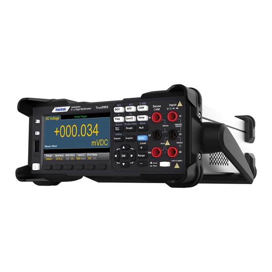
To adjust the handle of the digital multimeter, hold the handles on both sides and pull them outward. Then rotate the handle to the desired position. The operation is shown in the following picture. Fig. 1-1 Adjusting the handle Fig. 1-2 Placing the instrument The front panel... - Page 13 HDM3000 front panel sketch map Attachments Descriptions USB port Help key Preset/Default key Display Measuring configuration and operation key Connecting terminal Front/Rear switch Soft key Power key Note: Text is provided on some front panel keys. This indicates that the key has a function that you can access by pressing and releasing [Shift] before pressing the key.
- Page 14 The front panel menu references The following table summarizes the front panel keys and menu structure. Keys Application Configure DC voltage measurement, including DCV ratio measurement: Range: Automatically adjust range (default), 100 mV, 1 V, 10 V, 100 V or 1000V Aperture PLC: 0.02, 0.2, 1, 10, 100.
- Page 15 Aperture PLC: 0.02, 0.2, 1, 10, 100. Default value: 10 Auto Zero: Off or On (default) Keys Application Configure 4 wire resistance measurement. Range: 100 Ω, 1 kΩ, 10 kΩ, 100 kΩ, 1 MΩ, 10 MΩ or 100 MΩ. Note: The approximate current sourced for each range (for example, ~1mA) is shown on each range softkey.
- Page 16 Settings of RTD 2W or RTD 4W: R0: R0 is an RTD nominal resistor at 0 ℃. The default value is 100 Ω Aperture PLC: 0.02, 0.2, 1, 10, 100. Default value: 10 Units: °C, °F, or K Settings of Thermis2W and Thermis4W: Aperture PLC: 0.02, 0.2, 1, 10, 100.
- Page 17 Store and invoke instrument state and preferences. Configure the I/O interface Perform system administration tasks, including calibration. Configure user preferences. Perform file management activities Learn about the instrument, see the most recent error message, or clear the error message. Select manual or Auto range. Press to manually increase the range, press to manually reduce the range.
- Page 18 [Math] Key The availability of Math soft keys varies by measurement function. Soft keys Description Null Enable/disable use of null values and specify null value to use. dB / dBm Configure dB,dBm. Statistical information Enable, disable, and clear statistics. Limiting value Enables or disables upper and lower limits.
- Page 19 Soft keys Description Store/Recall Store and recall status and preference files, set boot default values. Manage Files Perform basic file management tasks and screen capture. I/O Config Configure LAN. Test/Admin Perform self – test, calibration, firmware update tasks System Setup Set user preferences, date, and time.
-
Page 20: The Rear Panel
The rear panel Connect the terminals and the current input fuse. The multimeter uses two types of fuses to provide input protection for small and large current ranges. The internal fuse provides the maximum protection limit of 10.5A for the input of large current range. The fuse will be blown when the input current exceeds 10.5A. - Page 21 If needing replacement, please contact Qingdao Hantek Electronic Co., Ltd. The fan The GPIB interface (non-standard) This interface can be configured using the Keysight IO Libraries Connection Expert utility. Power jack This multimeter can input two specifications of AC power supply. Connect alternating current to the multimeter through the socket using the power cord provided in the attachment.
-
Page 22: Models And Options
4) Replace the specified specification of the fuse. 5) Put the fuse holder into the card slot. Attention To avoid electric shock or fire, use the specified fuse and ensure that the fuse bracket is not short-circuited. 11. Voltage selector Select the correct voltage range according to the AC specification you are using. -
Page 23: First Use Of The Multimeter
If the instrument is still not started after checking without error, please check whether the power fuse has been blown. If necessary, please replace the fuse. If the instrumentis still not started after the above check, please contact Qingdao Hantek Electronic Co., Ltd. -
Page 24: Measuring Connection
Measuring connection This multimeter provides a variety of measuring functions. After selecting the required measuring function, connect the measured signal (device) to the multimeter as shown in the following figure. In the process of measurement, do not switch the measuring function at will, otherwise it may damage the multimeter. - Page 25 Resistance Measurement (2-wire) Resistance Measurement (4-wire) Capacitance Measurement Frequency/Period Measurement Continuity Measurement Diode Measurement...
-
Page 26: Chapter 2 Features And Functions
Chapter 2 Features and Functions This section contains detailed information about instrument features. This chapter outline: Measurement Triggering and Readings Probe hold Mathematics introduction Display introduction Utility Menu Introduction ... -
Page 27: Measurement
Step 1: Configure the test leads, as shown below. Step 2: Press [DCV] on the front panel. Step 3: For HDM3000, Press Aperture and select the number of power line cycle (PLC) for measurement. Only 1, 10 and 100 PLCs provide normal mode (line frequency... - Page 28 Choose 100 PLC to provide the best noise suppression, but the slowest measurement speed: For the HDM3000, by default Aperture NPLC=10PLC, use the Up/Down arrow keys to specify the integration time in the Power Line Cyclings (PLC) for measurement.
- Page 29 DCV Ratio The DCV Ratio key enables or disables DCV Ratio measurement. Note that the Auto Zero soft key will disappear when DCV proportional measurement is enabled. This is because Auto Zero cannot be disabled during DCV Ratio. This ratio is the ratio of the voltage at the input terminal to the reference voltage. The reference voltage is the difference between two separate measurements.
- Page 30 The AC voltage This section describes how to configure AC voltage measurement from the front panel. Select the default delay to give the correct first reading for most measurements. For the most accurate measurements, the input that prevents the RC time constant must be stabilized to 1/50 of the AC signal level.
- Page 31 manually selected range, auto range adjustment is more convenient but can lead to slower measurement. Auto range adjustment can turn the range up to 120% of the current range and down to less than 10% of the current range. Step 4: Press AC Filter and select Filter for measurement. The instrument uses three different AC filters, allowing you to optimize low frequency accuracy.The three filters are 3 Hz, 20 Hz, and 200 Hz, and in general, you should choose the highest frequency filter whose frequency is less than the frequency of the signal you are measuring, because a...
- Page 32 Step 1: Configure the test leads, as shown below. On the HDM3000, you can also configure the measurement using the 10A terminal, which is recommended when measuring currents greater than 3A: Step 2: Press [DCI] on the front panel.
- Page 33 measurement range automatically changes to 10 A. Step 5: Press Range to choose a range for measurement. You can also use the [+], [-] keys on the front panel to select the range. Auto (auto range adjustment) automatically select range for measurement based on input. Compared with manually adjusted range, automatic range adjustment is more convenient but can lead to slower measurement.
- Page 34 This section describes how to configure AC current measurement from the front panel. Step 1: Configure the test leads, as shown below. On the HDM3000, you can also configure the measurement using the 10A terminal, which is recommended when measuring currents greater than 3.0A: Step 2: Press [ACI] on the front panel.
- Page 35 manually adjusted range, automatic range adjustment is more convenient but can lead to slower measurement. Auto range adjustment can turn the range up to 120% of the current range and down to less than 10% of the current range. Press More to toggle between the two pages of settings.
- Page 36 Step 2: press the front panel [Ω 2 w] or [Ω 4 w]. The following menu appears. (Ω 4Wmenu does not include Auto Zero) Step 3: For the HDM3000, use the Up/Down arrow keys to specify the integration time in the Power Line Cycle Number (PLC) for measurement with Aperture NPLC=10PLC...
- Page 37 suppression. Choose 100 PLC to provide the best noise suppression but the slowest measurement speed: 4: Press Range to choose a range for measurement. You can also use the [+], [-] keys on the front panel to select the range. Auto (auto range adjustment) automatically select range for measurement based on input.
- Page 38 Measurements of connection changes after null operation The temperature This section describes how to configure 2 and 4-wire temperature measurements on the front panel. Step 1: Configure the test leads, as shown below. 2-wire temperature: 4-wire temperature: Step 2: Press [Temp] on the front panel. The following menu will appear. Step 3: Press Probe to select the probe type.
- Page 39 Step 4: For 2-line measurements, the Auto Zero soft key is available. Auto Zero: Auto Zero: Auto Zero provides the most accurate measured value but requires additional time to perform the reset-to-zero measurement. With Auto Zero enabled (ON), the DMM makes an internal measurement of the offset after each measurement and then the offset value is subtracted from the previous reading.
- Page 40 Step 2: Press the one on the front panel Step 3: To remove the test lead capacitance, do the following operations: Disconnect the probe end of the positive and negative test leads from the test circuit and leave it open. Press Null.
- Page 41 The continuous measurement method is as follows: ≤ 10 Ω Display measured resistance and buzzer (if buzzer is enabled.) 10 Ω to 1.2 k Display measured resistance, no buzzing > 1.2 k Ω Display OPEN, no buzzing The diode This section describes how to configure diode tests on the front panel. Step 1: Configure the test leads, as shown below.
- Page 42 This section describes how to configure frequency and period measurements from the front panel. Step 1: Configure the test leads, as shown below. Step 2: Press [Freq] on the front panel, then use the first soft key to select a frequency or period measurement.
- Page 43 Step 5: Press Gate Time and select a measurement gap of 10 ms, 100 ms(default), or 1 s(integral Time). Step 6: Timeout can be used to control the frequency or period that the instrument waits before the Timeout when there is no signal to measure the time. If it sets to 1 s, the instrument will wait 1 second before time-out.
- Page 44 To select Auxiliary measurements from the front panel, first select the primary measurement function and then press Display: Press 2nd Meas and select Auxiliary Measurement. The main measurement functions of each digital multimeter model and their related auxiliary measurements include: Main measurement function HDM3000 Auxiliary Measuring function frequency frequency frequency cycle...
-
Page 45: Triggers And Reading
Triggers and Reading The trigger mode and large reading memory on HDM3000 series digital multimeters provide a wide range of applications for them. Instrument trigger mode The result of the trigger is that the measurement results are collected on a digital multimeter. - Page 46 Both Single and Ext modes can be buffered to a trigger, which means that if you press [Single] or receive an external trigger while making a series of measurements, the instrument will complete the series of measurements and then immediately start a new series of measurements based on the trigger. If multiple [Single] or external triggers are emitted during a series of measurements, all of them will be received after the first trigger is dropped.
- Page 47 Store and erase readings You can store up to 1,000 measurements in the HDM3000 reading memory. The readings are stored in a first-in, first-out (FIFO) buffer. If the reading memory is full, the data stored the longest will be lost when new readings are taken.
-
Page 48: Probe Hold
Clear reading memory The following operations can clear the reading memory: Change the measurement function Press any Clear Readings soft key Turn in or turn out of Probe Hold Change of temperature unit Change any dB/dBm parameter ... -
Page 49: Mathematics - Introduction
readings without looking at the display.You can generate up to eight readings and keep them on the display for later review. These readings may be of different measurement types, and you can clear the readings displayed at any time. In the Probe Hold mode, the measuring settings can be optimized in order to reliably detect stable signal (when exiting Probe Hold, these settings will restore to their original values). - Page 50 The following mathematical functions are available for the HDM3000: Null DB/dBm scaling statistics limit Mathematics - Null function A null reading is a value that is subtracted from all subsequent measurements. This value is specific to the current function, even when you exit the function and return to use it.
- Page 51 DB and DBM functions can be accessed through the second soft key in the [Math] menu. When the first soft key in the dB/dBm menu is enabled (as shown below), you will see one of the following menus: When the function is dB: When the function is dBm: The dB scaling Each dB measurement is the difference between the input signal and the stored...
- Page 52 Note: To accurately display statistics for AC measurements in front panel mode, you must use the default manual trigger Delay ([Acquire] >Delay Man). The first soft key on this menu (shown below) can hide or show statistics below the data display. If DB or DBM scaling is used, the mean and standard deviation are not shown.
- Page 53 The first soft key enables or disables the limit. The second and third soft keys specify the limits to be high and low values, or as a range at either end of the middle value. For example, a Low limit value of -4 V and a High limit value of +7 V correspond to a Center value of 1.5 V and a Span value of 11 V.
- Page 54 Even when the trend line moves out of the limit area, the boundary remains red. When the trend line is within the limit, you can reset the boundary to green by pressing Clear Condition. Also note that the newly displayed measured number (under +09.994 VDC) indicates whether the measurement is within the limit.
- Page 55 The bar meter The bar meter (below) uses the same color scheme. The green limit boundary on the left indicates that the lower limit has not been exceeded, while the red limit boundary on the right indicates that the upper limit has been exceeded. The numbers 0 to 259 below the pale red limit area indicate the number of times each limit has been exceeded, and the word FAIL indicates that the limit has been exceeded.
-
Page 56: Display - Introduction
Display - Introduction By default, the instrument displays the reading in digital form. You can also select bar meter, trend chart or histogram display: For "digital" and "bar meter" displays, many of the main measurement functions allow the display of auxiliary measurement results. Select Display Press the Key, and then press the Display soft key to select the Display... - Page 57 measured the display Potential) or histogram. results on screen. The accurate the display measured value cannot screen. be obtained on the front panel. The number By default, the instrument displays readings in digital form: Add tables You can use the Label soft key to add a large text label to the screen. For example, you can use it to represent measurements being made using the DMM.
- Page 58 Enter the text, and then press Label Text, after that use the soft keys and the arrow keys on the front panel to modify the label (as shown in the figure below). Then press Done. Label fonts will automatically shrink to accommodate longer labels. Select an auxiliary measurement Press 2nd Meas to select and display auxiliary measurements.For example, for the DCV measurement function, you can choose ACV as the auxiliary measurement...
- Page 59 For more information about auxiliary measurements that can be used in each measurement function, see Auxiliary measurements. The display digit soft key can select the digits displayed by the multimeter. For example, the figure below shows 6½ bits. By comparison, this figure shows 4½ bits.
- Page 60 The AUTO soft key specifies that the number of bits to be displayed is based on other specific function settings, such as measurement aperture, NPLC Settings. The measurement will be rounded, not truncated. The bar meter The bar meter (shown below) adds a move bar below the standard digital. The Display and Digit Mask soft keys work just as they do in a digital display.
- Page 61 The Scale soft key specifies the horizontal scale: Default sets the scale equal to the measurement range. Manual allows you to configure demarcations, either as High and Low values, or as Span values around the Center value. For example, a scale of -500 Ω Low value and 1000 Ω...
- Page 62 Trend Chart (Continuous Measurement Mode) To select a trend chart, press [DISPLAY] and then the DISPLAY soft key: In continuous measurement mode, the trend chart shows the trend of the data over a period of time: The data will be collected and displayed in a pixel bars, as shown below. Recent/All The Recent/ALL softkey can display all data in the trend chart (ALL) or only the recent data (Recent).
- Page 63 If you have enabled Limits, the (Limits) soft key will also appear. This sets the vertical scaling to match the limit value. Histogram Histogram shows the measurement data in the form of a graphical representation of the distribution of the measurement data. In a histogram display, data is grouped in barss represented by vertical bars.
-
Page 64: Utility Menu - Introduction
factors so that the new bars range covers the new reading. The number of bars shown is a function of the number of readings received: 0 to 100 readings = 10 bars, 101 to 500 readings = 20 bars, 501 to 1000 readings = 40 bars, 1001 to 5000 readings = 100 bars, 5001 to 10000 readings = 200 bars, >10000 readings = 400 bars. - Page 65 Utility provides the following functions: Utility – Store and recall the status and preference files. The "Utility" menu is shown below. Press Store/Recall to store and recall the status and preference files. In general, the status file stores volatile Settings associated with the measurement. Preferences are instrument-related non-volatile parameters, but not any particular measurement value.
- Page 66 Recall Settings You can use Recall Settings to browse to the file to be recalled. Use the arrow keys to navigate to the desired status file (*.sta) or preference file (*.prf). Power On Power On selects the loaded state when powered On. This may be the state when the power is switched off (Last), or the state selected by the User(User Defined), or the Factory Defaults.
- Page 67 folder or file you want to Delete. Press Select >Perform Delete >Done Folder - To create a folder, press Browse to browse to the internal or external location of the Folder, press File Name to enter the folder name, then press Done.
- Page 68 Press [Done] or [Cancel] to end the input. Utility menu - I/O configuration I/O Config is used to configure the I/O parameters for remote operation over a LAN, GPIB(optional) interfaces. LAN RESET resets the LAN with its current settings and enables DHCP and MDNs.
- Page 69 Self-Test verifies that the instrument is running normally. The calibration Calibrate provides access to the instrument calibration process. The firmware update Firmware Update allows you to update the instrument's firmware to a new version. Utility menu - System Settings System Setup allows you to configure user preferences and set the date and time.
-
Page 70: Chapter 3 Measurement Guidance
You can enable or disable the display and adjust the brightness (10 to 100%). If you turn off the display, press any of the keys on the front panel to turn it on again. By default, after eight hours of inactivity, the screensaver turns off and the display does not display. -
Page 71: Precautions For Dc Measurement
Precautions for DC measurement Thermoelectric EMF error Thermoelectric voltage is the most common error source in low level DC voltage measurement. Thermal voltages are generated by connecting circuits using heterogeneous metals at different temperatures. Each connection between the metals will form a thermocouple which will generate a voltage proportional to the connection temperature as shown in the table below. -
Page 72: Noise Rejection
significant proportion of the input resistance of the multimeter itself. The following figure is a schematic diagram of this error source. 理想 万用表 VS = ideal DUT voltage RS = DUT source resistance Ri = multimeter input resistance (10MΩ or >10GΩ) If you want to reduce the load error effect and reduce the noise interference, for 100 mVDC, 1VDC and 10 VDC range, the input impedance of a multimeter can be set to ">... - Page 73 Common Mode Rejection (CMR) Ideally, the multimeter is completely isolated from the ground - based circuit. However, there is some resistance between the multimeter input LO terminal and the ground, as shown in the figure below. This creates an error in measuring the low voltage floating with respect to the ground.
-
Page 74: Precautions For Resistance Measurement
not grounding the input terminals. If the multimeter must be ground-based, connect it to a common ground point with the device under test. If possible, also connect the multimeter and the device under test to the same power outlet. Precautions for resistance measurement The multimeter provides two resistance measurements: 2-wire and 4-wire resistance measurement. -
Page 75: True Rms Ac Measurement
If the energy outside the effective bandwidth of the multimeter is negligible in the voltage or current waveform, the HDM3000 can accurately measure its RMS. HDM3000 has an effective AC voltage bandwidth of 300 kHz and an effective AC current bandwidth of 10 kHz. - Page 76 Asymmetric waveforms, such as pulse trains, contain DC components that are filtered out by AC-coupled true RMS measurements. AC coupled true RMS measurements are ideal for measuring small AC signals with DC offset, such as AC ripple measurements in DC power supply output. However, in some cases it is necessary to measure AC+DC RMS values.
-
Page 77: Capacitance
band width (200 μs); The other has narrow bandwidth (including 6.7 μs). The bandwidth of ACV path in digital multimeter is 300 kHz. Therefore, frequency components above 300 kHz cannot be measured. Note that the spectrum sine (πfT)/πfT of the narrow pulse is clearly beyond the effective bandwidth of the instrument. - Page 78 The response curve during charging is shown as follows: The capacitance is calculated by measuring the voltage change (DV) that occurs during the "short aperture" period (Dt). The measurement was repeated at two different time periods during which the exponential rise occurred. The algorithm extracts data from these four points and calculates the exact capacitance value by linearizing the exponential rise that occurs during the "short aperture"...
-
Page 79: Chapter 4 Calibration And Adjustment Steps
Capacitors with high power factor or other non-ideal characteristics can affect capacitance measurements. Capacitors with a high power factor can make a difference in the measurement when using a multimeter and some other single-frequency methods of LCR meters. The single-frequency method can also be used to detect additional variations in different frequencies. -
Page 80: The Calibration Process
accurate measurement results. This chapter is as follows The calibration process The calibration procedure The calibration process This section covers the procedure for adjusting (calibrating) the performance of the instrument. - Page 81 Note: It is not possible to calibrate the diode or continuity separately because these functions are based on calibrated resistance measurements. In addition, there is no way to calibrate the gate timing because this function is controlled by digital logic. Capacitance gain cannot be calibrated.
- Page 82 The AC Fluke5720A voltage The AC Fluke5720A current frequency Fluke5720A High current Fluke5725A Capacitance Sca-1uf capacitor standard (optional) Gain and flatness calibration adjustment overview The instrument will store the new flatness correction constant whenever this procedure is executed. The flatness constant adjusts the digital multimeter for AC voltage and AC current measurements over the entire available input frequency band.
-
Page 83: The Calibration Procedure
2Vrms ~ 11Vrms/9.5kHz ~ FREQ 25kHz The calibration procedure The following calibration procedure applies to HDM3000 DMM. Perform the calibration procedure in the order listed in this document. SelfTest and reset-to-zero calibration DC voltage gain calibration DC current gain calibration... - Page 84 This process uses a low-heat short circuit block mounted on the input connector. For HDM3000, two short circuit blocks are recommended. One is on the front panel and one is on the back panel. Short-circuit is suitable for DCV, DCI, RES, FRES, ACV,ACI zero calibration.
- Page 85 Calibration value and repeat the Calibration Step. Repeat steps 1 through 3 for each gain calibration point shown in the table. The calibration points of HDM3000 are as follows: gear Calibration...
- Page 86 Calibration Step Failed, check the input value, range, function, and the input calibration value and repeat the calibration steps. Repeat steps 1 to 3 for each gain calibration point shown in the table. The calibration points of HDM3000 FRES are as follows: gear Calibration point 1 100 Ω...
- Page 87 AC voltage gain and flatness calibration Configuration: AC voltage Configure the ranges shown in the following table. Apply the input signal shown in the Input column. Input the input voltage range for the actual application. The message Calibration Step Succeeded indicates success. If the display shows Calibration Step Failed, check the input value, range, function, and the input calibration value and repeat the calibration steps.
- Page 88 AC Current Gain and Flatness Calibration Configuration: AC current Configure the ranges shown in the following table. Apply the input signal shown in the Input column. Input the input current range for the actual application. The message Calibration Step Succeeded indicates success. If the display shows Calibration Step Failed, check the input value, range, function, and the input calibration value and repeat the calibration steps.
- Page 89 Repeat steps 5 through 7 for each frequency shown in the table. The HDM3000 CAP calibration points are as follows: gear Calibration point 1...
-
Page 90: Chapter 5 Appendix
10uF 10uF 100uF 100uF Chapter 5 Appendix Appendix A: HDM3000 Digital Multimeter Annex... -
Page 91: Appendix B: Warranty Summary
Appendix B: Warranty Summary Qingdao Hantek Electronic Co., LTD. commits that its instrument host is without any material and process defects in the product warranty period. During the warranty period, if the product is proved to be defective, Qingdao Hantek Electronic... - Page 92 Qingdao Hantek Electronic Co., Ltd. Other than the warranties provided by this summary or any other applicable warranty card, Qingdao Hantek Electronic Co., Ltd. does not provide any other warranties, express or implied, including, but not limited to, any implied warranties of merchantability and fitness for special purposes of the products.
Need help?
Do you have a question about the HDM3000 and is the answer not in the manual?
Questions and answers