Table of Contents
Advertisement
Quick Links
Advertisement
Table of Contents

Related Manuals for Hantek HDM3000


Summary of Contents for Hantek HDM3000
- Page 1 Quick Guide HDM3000 Digital Multimeter Version: 1.0...
-
Page 2: Guaranty And Declaration
Qingdao Hantek Electronic Co., Ltd shall not be liable for all possible errors in this manual, or for any information provided in this manual, or for any incidental or consequential loss arising from the use of this manual. - Page 3 If you suspect there is something wrong with the product, please contact maintenance personnel authorized by Hantek for testing. Any maintenance, adjustment or replacement of components must be performed by repairmen authorized by Hantek. Maintain good ventilation. Poor ventilation may cause the temperature of the instrument rising and then lead to damage to it.
- Page 4 instrument in anti-static area. Before connecting the cable to the instrument, the inner and outer conductors should be grounded briefly to release the static electricity. Pay attention to carrying safety. To avoid the instrument sliding in the process of carrying, causing damage to the keys on the panel, the knobs or interfaces, please pay attention to carrying safety.
- Page 5 These devices include most small appliances, test equipment, and other devices plugged into branch sockets. The HDM3000 can be used to make measurements where the HI and LO input terminals are connected to power mains (up to 300 VAC) in these devices, or to branch sockets themselves.
-
Page 6: Safety Terms And Symbols
Safety Terms and Symbols Terms used in this manual. The following terms may appear in this manual: Warning A warning statement indicates conditions and actions that may endanger the operator. Attention The attention statement indicates conditions and actions that may cause damage to or loss of data. -
Page 7: Maintenance And Cleaning
Maintenance and Cleaning Maintenance Do not place the instrument in a place exposed to sunlight for a long time. Cleaning Please clean the instrument frequently according to the condition of the instrument. To clean the exterior surface, perform the following steps: Turn off the power. -
Page 8: Chapter 1 Quick Start
Chapter 1 Quick Start Format conventions in the document: Keys: For functional keys on the front panel of the instrument, a key icon is used in this book. For example: The DC voltage measurement function key is represented by This chapter guides the user to quickly know the basic information of the multimeter such as the front and rear panels, the user interface and measuring connections. -
Page 9: General Inspection
If the instrument is damaged due to transportation, the consigner or carrier shall be liable for the damage to the instrument. Qingdao Hantek Electronic Co., LTD. will not carry out free repair or replacement. -
Page 10: Adjust The Handle
Adjust the handle. To adjust the handle of the digital multimeter, hold the handles on both sides and pull them outward. Then rotate the handle to the desired position. The operation is shown in the following picture. Fig. 1-1 Adjusting the handle Fig. -
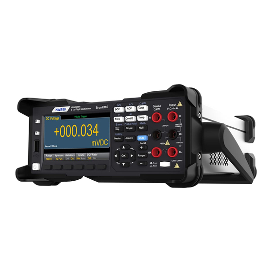
Page 11: The Front Panel
The front panel HDM3000 front panel sketch map Attachments Descriptions USB port Help key Preset/Default key Display Measuring configuration and operation key Connecting terminal Front/Rear switch Soft key Power key Note: Text is provided on some front panel keys. This indicates that the key has a function that you can access by pressing and releasing [Shift] before pressing the key. - Page 12 The front panel menu references The following table summarizes the front panel keys and menu structure. Keys Application Configure DC voltage measurement, including DCV ratio measurement: Range: Automatically adjust range (default), 100 mV, 1 V, 10 V, 100 V or 1000V Aperture PLC: 0.02, 0.2, 1, 10, 100.
- Page 13 Aperture PLC: 0.02, 0.2, 1, 10, 100. Default value: 10 Auto Zero: Off or On (default) Keys Application Configure 4 wire resistance measurement. Range: 100 Ω, 1 kΩ, 10 kΩ, 100 kΩ, 1 MΩ, 10 MΩ or 100 MΩ. Note: The approximate current sourced for each range (for example, ~1mA) is shown on each range softkey.
- Page 14 Settings of RTD 2W or RTD 4W: R0: R0 is an RTD nominal resistor at 0 ℃. The default value is 100 Ω Aperture PLC: 0.02, 0.2, 1, 10, 100. Default value: 10 Units: °C, °F, or K Settings of Thermis2W and Thermis4W: Aperture PLC: 0.02, 0.2, 1, 10, 100.
- Page 15 Store and invoke instrument state and preferences. Configure the I/O interface Perform system administration tasks, including calibration. Configure user preferences. Perform file management activities Learn about the instrument, see the most recent error message, or clear the error message. Select manual or Auto range. Press to manually increase the range, press to manually reduce the range.
- Page 16 [Math] Key The availability of Math soft keys varies by measurement function. Soft keys Description Null Enable/disable use of null values and specify null value to use. dB / dBm Configure dB,dBm. Statistical information Enable, disable, and clear statistics. Limiting value Enables or disables upper and lower limits.
- Page 17 Soft keys Description Store/Recall Store and recall status and preference files, set boot default values. Manage Files Perform basic file management tasks and screen capture. I/O Config Configure LAN. Test/Admin Perform self – test, calibration, firmware update tasks System Setup Set user preferences, date, and time.
-
Page 18: The Rear Panel
The rear panel Connect the terminals and the current input fuse. The multimeter uses two types of fuses to provide input protection for small and large current ranges. The internal fuse provides the maximum protection limit of 10.5A for the input of large current range. The fuse will be blown when the input current exceeds 10.5A. - Page 19 If needing replacement, please contact Qingdao Hantek Electronic Co., Ltd. The fan The GPIB interface (non-standard) This interface can be configured using the Keysight IO Libraries Connection Expert utility. Power jack This multimeter can input two specifications of AC power supply. Connect alternating current to the multimeter through the socket using the power cord provided in the attachment.
-
Page 20: Models And Options
4) Replace the specified specification of the fuse. 5) Put the fuse holder into the card slot. Attention To avoid electric shock or fire, use the specified fuse and ensure that the fuse bracket is not short-circuited. 11. Voltage selector Select the correct voltage range according to the AC specification you are using. - Page 21 If the instrument is still not started after checking without error, please check whether the power fuse has been blown. If necessary, please replace the fuse. If the instrumentis still not started after the above check, please contact Qingdao Hantek Electronic Co., Ltd.
- Page 22 Measuring connection This multimeter provides a variety of measuring functions. After selecting the required measuring function, connect the measured signal (device) to the multimeter as shown in the following figure. In the process of measurement, do not switch the measuring function at will, otherwise it may damage the multimeter.
- Page 23 Resistance Measurement (2-wire) Resistance Measurement (4-wire) Capacitance Measurement Frequency/Period Measurement Continuity Measurement Diode Measurement...
Need help?
Do you have a question about the HDM3000 and is the answer not in the manual?
Questions and answers