
Related Manuals for herdstar BINTRAC HouseLink HL-10C


Summary of Contents for herdstar BINTRAC HouseLink HL-10C
- Page 1 Installation and Operation Manual Installation and Operation Manual HouseLink HL-10C HL-10C Installation Manual Rev 2.0 Part Number MAN-000015...
-
Page 2: Table Of Contents
CAN Classic Setup .................................. 7 Operational Specifications ..............................8 Wiring Diagram ..................................9 is a registered trademark of HerdStar, LLC. Copyright © 2021 HerdStar, LLC. All rights reserved. Printed in the USA 1400 Madison Avenue, Suite 504, Mankato, MN 56001 PH: 507-344-8005 FAX: 507-344-8009 www.herdstar.com... -
Page 3: Description
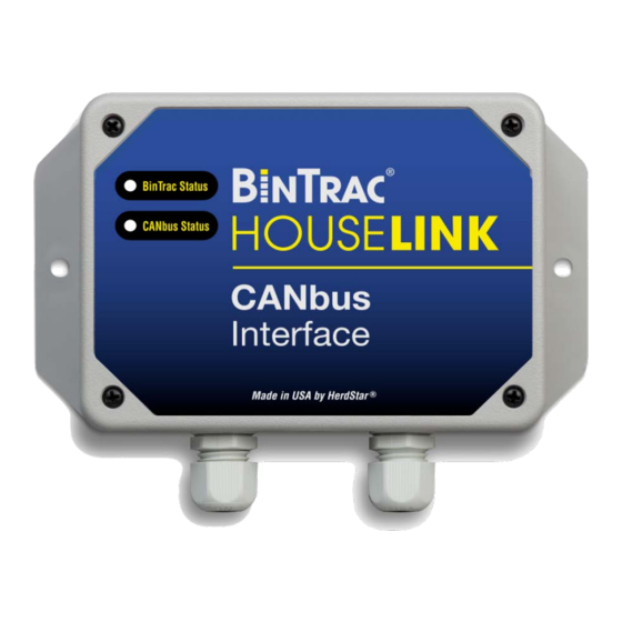
Installation and Operation Manual Description The HouseLink HL-10C provides a CAN bus interface to the CAN bus controller. The HouseLink HL-10C is designed to be used with the BinTrac Bin Weighing system. One HouseLink HL-10C can be connected to one BinTrac indicator and can connect with a maximum of four bins. Installation 1. -
Page 4: Bintrac Indicator Setup
Installation and Operation Manual 5. The unit has an 8-position dip switch that needs to be set up for configuration. Switches 1, 7, and 8 are set to ON from the factory. See Table 2 for dip switch identification. Lower bit of 0x40 offset CANopen device address. This DIP is set if the CANopen DIP 1 address should be 0x40 + 0x01 Upper bit of 0x40 offset CANopen device address. -
Page 5: Testing And Calibration
Installation and Operation Manual Testing and Calibration Reset/Test button: Once the unit is wired up properly, the unit can be put into one of five test modes. These modes are useful when setting up and testing with the CAN bus controller. Test 1 –... - Page 6 Installation and Operation Manual Here you see the CAN bus address (CAN ID) and if it is connected. Utilize address 41 for bins 1-4 and address 42 for bins 5-8. | Technical | Installation | Manual installation | Silo weighing boxes Select the number of BinTrac bins enabled.
-
Page 7: Can Classic Setup
Installation and Operation Manual For correct connection of silo load cells, see menu | Technical | Installation | Show connection CAN Classic Setup The following two settings must be configured when using properly on the CAN bus controller to allow for accurate weight communication with the BinTrac system. -
Page 8: Operational Specifications
Installation and Operation Manual Operational Specifications CAN Bus version: Compatible with ISO 11898 STANDARDS Operating Temperature Range: -40°C to +60°C (-40°F to +140°F) Operating Voltage Range: 10.5 VDC to 27.0 VDC Humidity: 5% to 95% (non-condensing) Environmental Air: No corrosive gasses permitted Enclosure Type: Non-Sealed Wiring Type:... -
Page 9: Wiring Diagram
Installation and Operation Manual Wiring Diagram HL-10C Installation Manual Rev 2.0 Part Number MAN-000015...
Need help?
Do you have a question about the BINTRAC HouseLink HL-10C and is the answer not in the manual?
Questions and answers