
Related Manuals for Fervi 0054/10

Summary of Contents for Fervi 0054/10
- Page 1 OPERATION AND MAINTENANCE MANUAL Hydraulic body frame repair kit Art. 0054/10 ORIGINAL INSTRUCTIONS...
- Page 2 Manual on the date of issuance and listed herein; On the other hand, the machine may also be subject to important technical changes in the future, without the manual being updated. Therefore, see FERVI for information about modifications that could be implemented. REV. 2 November 2013...
-
Page 3: Table Of Contents
MACHINES AND ACCESSORIES CONTENTS GENERAL INFORMATION................4 GENERAL SAFETY WARNINGS ..............5 Technical support......................5 Other provisions ......................5 DESCRIPTION OF THE HYDRAULIC UNIT ..........6 Identification Plate and Pictograms ................7 Safety devices .......................7 TECHNICAL SPECIFICATIONS ..............8 IMPROPER USE AND CONTRAINDICATIONS..........8 TRANSPORTING, LIFTING AND MOVING ........... -
Page 4: General Information
The purpose of this manual is to provide the knowledge necessary for the use and maintenance of the Hydraulic body frame repair kit Art. 0054/10, and create a sense of responsibility and a knowledge of the possibilities and limitations of the tool entrusted to the operator. -
Page 5: General Safety Warnings
MACHINES AND ACCESSORIES 2 GENERAL SAFETY WARNINGS Even if you are already familiar with the Hydraulic Pump, you must read this manual carefully to acquire full knowledge of the machine and general precautions to be observed during operation. Risks related to Using the Machine ... -
Page 6: Description Of The Hydraulic Unit
MACHINES AND ACCESSORIES 3 DESCRIPTION OF THE HYDRAULIC UNIT The hydraulic unit Art. 0054/10 is designed to provide pressure to cylinders or single-acting hydraulic tools. The pump must be used on surfaces that are supportive, flat, smooth, and adequately strong and hard. -
Page 7: Identification Plate And Pictograms
MACHINES AND ACCESSORIES 3.1 Identification Plate and Pictograms The identification plate is affixed to the hydraulic cylinder. Figure 2 – Identification plate. AXIMUM NOMINAL CAPACITY The plate indicates the maximum thrust capacity, that the pump in combination with the supplied hydraulic piston can produce in standard conditions, i.e. when: ... -
Page 8: Technical Specifications
MACHINES AND ACCESSORIES 4 TECHNICAL SPECIFICATIONS Description Unit of measurement Art. 0054/10 Lifting capacity 10,000 Pressure 63.7 Piston Height Piston stroke Kit weight 5 IMPROPER USE AND CONTRAINDICATIONS THE FOLLOW ARE STRICTLY PROHIBITED!: Using the hydraulic body frame repair kit to lift persons and/or animals that could fall. -
Page 9: Transporting, Lifting And Moving
MACHINES AND ACCESSORIES 6 TRANSPORTING, LIFTING AND MOVING The operator may manually lift the pump for transporting. Make sure the drain valve screw is fully tightened. The operator should grasp the pump with both hands, using the lever and the base of the hydraulic cylinder as lifting points. -
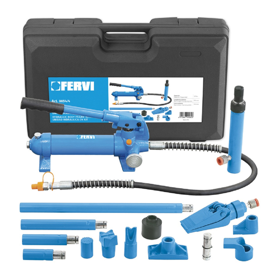
Page 10: Commissioning
MACHINES AND ACCESSORIES 7.1 Commissioning To commission the hydraulic body frame repair kit for use, it is necessary to do the following: 1. Take out all the necessary components from the case. Verify the presence of all the components. igure 5 - Mould case 2. -
Page 11: Pressure Release
MACHINES AND ACCESSORIES 7.2 Pressure Release To lower the piston rod on the hydraulic cylinder, decrease the pressure inside the circuit by opening the vent valve and slowly turning the knob anti-clockwise (Figure 8) Figure 8 – Control knob. 8 MAINTENANCE The purpose of this chapter is to provide the timing and maintenance procedures required to maintain the Hydraulic Pump. - Page 12 MACHINES AND ACCESSORIES completely release the pressure by turning the knob anti-clockwise; as shown in Figure 8; unscrew the oil filler cap (see Figure 9), with a screwdriver; add hydraulic mineral oil (fill up to the bottom edge of the opening); ...
-
Page 13: Troubleshooting
MACHINES AND ACCESSORIES 9 TROUBLESHOOTING The following table shows the type of defect / problem, possible causes, and possible remedies for the malfunction. The table is a useful aid for the maintenance technician when looking for problems with the machine. Fault Cause Solution... -
Page 14: Replacement Parts
Part No. Description Part No. Description 0054/10/01 Mould case 0054/10/06 Wedge head 0054/10/02 Extension cord 0054/10/07 V-shaped head 0054/10/03 Base plate 0054/10/08 Male connector 0054/10/04 Piston base 0054/10/09 Knurled saddle piston 0054/10/05 Piston foot 0054/10/10 Rubber saddle Page 14 of 17... -
Page 15: Hydraulic Cylinder
MACHINES AND ACCESSORIES 12.2Hydraulic cylinder Part No. Description Part No. Description 0054/10/R01 Protective plastic caps 0054/10/R09 Nut 0054/10/R02 Elastic ring 0054/10/R10 Spring 0054/10/R03 Piston 0054/10/R11 Screw 0054/10/R04 Elastic ring 0054/10/R12 Protective cap 0054/10/R05 Plain bearing 0054/10/R13 Ring 0054/10/R06 Nylon Washer... -
Page 16: Pump
MACHINES AND ACCESSORIES 12.3 Pump Page 16 of 17... - Page 17 0054/10/P27 Nylon ring 0054/10/P04 Tank 0054/10/P28 Sealing ring 0054/10/P05 Coupling shaft 0054/10/P29 O-Ring 0054/10/P06 Nylon ring 0054/10/P30 Nylon ring 0054/10/P07 Oil filter screw 0054/10/P31 Screw 0054/10/P08 Locking ring 0054/10/P32 O-Ring 0054/10/P09 Vent valve 0054/10/P33 Nylon ring 0054/10/P10 Screw 0054/10/P34 Piston...
Need help?
Do you have a question about the 0054/10 and is the answer not in the manual?
Questions and answers