Advertisement
Quick Links
Advertisement

Related Manuals for jbc XL Preheater Set


Summary of Contents for jbc XL Preheater Set
- Page 1 INSTRUCTION MANUAL XL Preheater Set Ref. PHXLE-KA...
-
Page 2: Table Of Contents
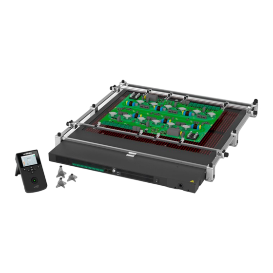
Packing List The following items are included: Heater Unit Console XL Preheater ......1 unit XL Preheater PCB Support ....1 unit Ref. PHXLE-1A (120V) Ref. PHXL-SA PHXLE-2A (230V) PHXLE-9A (100V) RJ45 Cable ....1 unit Kapton Tape ....1 unit Metallic Supports for PCB Ref. - Page 3 w w w.jbctools.com Features Heater Unit Heating Areas Fixing brackets for Zone A Zone B Thermocouple PHXL-SA Preheater Connectors x8 PCB Support (Type K) RJ45 Connector Main Switch to Console USB-B Connector RJ12 Connector to Robot Pedal Connector Button for foot Console folding and unfolding 2,8”...
- Page 4 Connections RJ45 Cable Ref. 0019914 Connection to electrical Network PHXLE-A can be connected to single-phase or three-phase networks. A power supply cable is required. Use the following table to determine the cable size and connection: Peak Current Cable Connection Wire Section Single-phase Three-phase Single-phase...
- Page 5 E 1:1 w w w.jbctools.com To conect your power supply cable to the Heater Unit do as follows: MONOPHASIC TRIPHASIC (100V to 230V) (173V to 400V) Cable grommet 1. Unscrew the four screws and remove the 2. Insert the cable through the cable grommet cover.
-
Page 6: Ref. Ph201
Height Adjustment PHXL-SA allows adjustment to 3 heights between the PCB and the heating area of the PHXLE-A heater unit. Select the adequate PH201, PH202, PH203 for your working level. Arrange the selected supports between the PCB and the Preheater to stabilize the PCB so as to avoid PCB deformatiion. Ref. - Page 7 w w w.jbctools.com Fast PCB Replacement The support lets you replace PCBs of the same batch fast and easily. Use the sliding guides to change the PCBs. Removing the PCB Loosen one sliding guide, pull back and lift out the PCB. Sliding guide Sliding guide knobs Placing another PCB...
-
Page 8: Thermocouple
Work Screen The Console offers an intuitive user interface which provides quick access to station parameters. Status bar 14:15 Status indicator Instant power º TC1 current supplied to and selected heater Temperature º Selected 150 º º º Thermocouple º current temp. -
Page 9: Kapton Tape
w w w.jbctools.com Setting Thermocouples Function Select Thermocouples from the Work mode menu to set them up. The thermocouples (TC) can work in three diferent ways depending on what is needed. · Control: the unit mantains the selected temperature. · Protection: the Heater Unit stops if the TC reaches the selected temperature. ·... - Page 10 Work Mode Temperature Mode Select Temp. mode from the Work mode menu. In this mode the heater unit maintains the selected temperature for the TC1 thermocouple as long as the other TC’s do not reach the control/protection temperature limit. Status bar 14:15 Status indicator...
- Page 11 w w w.jbctools.com Profiles Mode Select Profile Mode from the Work Mode Menu. In this mode the heater unit regulates the temperature of the TC1 thermocouple according to the selected profile as long as the other TCs do not reach the control/protection temperature limit. 14:15 PROFILE1 Stop...
- Page 12 JBC Set Profiles There are 3 profiles predefined by JBC: A, B and C. The difference between them is the number of steps: 2, 3 or 4. The thicker your PCB is and the more layers it contains, the more steps are needed to obtain a gradual warming.
- Page 13 w w w.jbctools.com Process Analysis By pressing Graphics in the main MENU, temperature of TC1 thermocouple and power figures in real time are displayed. Graphics 14:15 Power (%) Temperature Power[%] Ext.Temp[ºC] Switch Y axis between power and temperature System Notifications The following icons will be displayed on the screen’s status bar.
- Page 14 Insert a USB flash drive into the USB-A connector to export / import profiles. Update the Station Software 1. Download the JBC Update File from 2. Insert the USB flash drive to the console. www.jbctools.com/software.html and save The icon is diplayed while updating.
- Page 15 - Only if it is absolutely necessary and if cleaning with isopropyl alcohol (IPA) is not enough, it is recommended to use a scraper to remove dirt in the glass area. - Replace any defective or damaged parts. Use original JBC spare parts only. - Repairs should only be performed by a JBC authorized technical service.
- Page 16 Safety It is imperative to follow safety guidelines to protect health and prevent electric shock, injury, fire or explosions. - Do not use the units for any purpose other than PCB preheating. Incorrect use may cause fire. - The mains cable must be plugged into approved bases. Make sure that it is properly grounded before use.
- Page 17 w w w.jbctools.com Notes...
- Page 18 Notes...
- Page 19 Specifications XL Preheater Set PHXLE-1KA / PHXLE-2KA / PHXLE-9KA PHXLE-1A 120V. Input 120V 50/60Hz Fuse T20A PHXLE-2A 230V. Input 230V 50/60Hz Fuse T10A PHXLE-9A 100V. Input 100V 50/60Hz Fuse T20A - Maximum Power: 5400W - Heating Area (L x W): Zone A 510 x 200 mm / 20 x 7.9 in...
- Page 20 In order for the warranty to be valid, equipment must be returned, postage paid, to the dealer where it was purchased. Get 1 extra year JBC warranty by registering here: https://www.jbctools.com/productregistration/ within 30 days of purchase. This product should not be thrown in the garbage.
Need help?
Do you have a question about the XL Preheater Set and is the answer not in the manual?
Questions and answers