
Related Manuals for Tense RGT-12SVC


Summary of Contents for Tense RGT-12SVC
- Page 1 ELEKTRİK - ELEKTRONİK SAN.TİC.A.Ş. RGT-12SVC USER MANUAL Main Usage Areas ₺ Banks Hotels Oil Stations Schools Malls Factories www.tense.com.tr www.tenseenerji.com...
- Page 2 Index About RGT-12SVC What is the SVC (TCR)? Features Warnings Matters to be Considered in Power Factor Correction Points to Consider in Current Transformer Selection and Connection Maintenance of the Device Quick Installation Guide Measuring Screens Menu Screens 3P4W Connection Scheme...
- Page 3 Index Settings Current Transformer Menu Current Transformer Test Current Transformer Value Step Menu Step Values Step Measurement Step Time Settings Power Factor Correction Settings Step Control Manual Step Value Set Automatic Step Measurement Period Advanced Settings Menu Power Factor Correction Power Analysis Samples ModBus RS485 (Communication Settings) Operating Power...
- Page 4 Thus it endeavors to reduce the inductive/active and capacitive/active rates of the system. It is designed to make more sensible compensation at the unbalanced inductive and capacitive systems with RGT-12SVC TCR(SVC) step. What is the SVC (TCR) ? SVC is a new generation compensation system that works to minimize the capacitive power in the system by activating the reactors connected to the TCR (Thyristor Controlled Reactor) unit as much as necessary against the instantaneous capacitive power in the system.
- Page 5 Warnings Use the device according to our instructions. Avoid direct sun light in order not to harm the LCD screen. Leave at least 10 cm of space behind the device after mounting. Fix the device with apparatus which comes within the device by avoiding any kind of shake on the front cover of the board.
-
Page 6: Maintenance Of The Device
It is recommended that class of the current transformers (it can be also mentioned class, klas, kl, cl ) should be 0,5 which will be used at the compensations. Only X5A current transformers can be connected to the RGT-12SVC. Be careful about the absence of any load before the current transformers. Otherwise there can be differences between reactive and counter. -
Page 7: Enter Password
Quick Installation Guide Warning! Three-phase capacitor equivalent to 1/40 of current transformer ratio must be connected in the first three steps for current transformer test to be performed. Also, the current transformer connected to the device and the phase order of the voltages must be the same. Otherwise, the device will give phase inverse or step low warning. - Page 8 When current transformer test is successful, this page will be displayed on During the step measurement, this the screen. page will be displayed on the screen, all steps will be measured in order and If the operation is confirmed by pressing their values will be displayed on the the SET button, the device will automatically screen.
- Page 9 Measuring Screens Ratios(%) Ind. Cap. 1.000 Ind(%) Cosinus(Cos) 0.000kW Instant: L1: -1.000 Offset 0.000kVar Hourly : 0.000kVar Cap(%) 1.000 Daily 0.000kVA L3: -1.000 Off: 0.0kVar Energy : _____________________ _____________________ _____________________ TCR % R:23 S:23 T:23 TCR % R:23 S:23 T:23 TCR % R:23 S:23 T:23 Figure-1...
- Page 10 Menu Screens 1.000 Ind(%) 0.000kW 0.000kVar Enter Password! 0.000kVar Cap(%) PASS : 0000 0.000kVA Off: 0.0kVar _____________________ TCR % R:23 S:23 T:23 Figure-1 Figure-2 Menu.1.0 CURRENT TRANSFORMER MENU Menu.4.0 Menu.2.0 Figure-3 STEP MENU DEVICE SETTINGS MENU Menu.3.0 Figure-4 Figure-6 ADVANCED SETTINGS MENU Figure-5 Entering Settings: When SET button is pressed on any measurement page, the PASSWORD...
- Page 11 3P4W Connection Scheme...
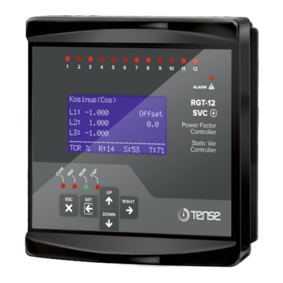
- Page 12 Screen Description 1- Stage Leds: The LEDs are lit when the steps are active. 2- Alarm Led: It is the LED that lights to alert the user in case of alarm. 3- Graphic LCD: It is the screen where all measurements, settings and notifications related to the device are transferred to the user.
- Page 13 How to Install the Device? Three-phase capacitor equivalent to 1/40 of current transformer ratio must be connected in the first three steps for current transformer test to be performed. Also, the Enter Password! current transformer connected to the device and the phase order of the voltages must be the same.
- Page 14 During the step measurement, this page will be displayed Step Measure. (kVAr) on the screen, all steps will be measured in order and their Please Wait! values will be displayed on the screen. L1:-3.333 Capacitor values are shown with a “-” sign and shunt 1.Step L2:-3.333 reactors are unsigned.
- Page 15 While in this page, press the SET button to enter the Menu.1.2.1 Current Transformer Value in the system. Current Trans. Value Current Transformer Value Entry page will be displayed on the screen. CTR: 1500 / 5A While on this page, use the UP and DOWN buttons to enter the Current Transformer Value in the system and then press the SET button to save.
- Page 16 How is the Current Transformer Test Performed? Three-phase capacitor equivalent to 1/40 of current transformer ratio must be connected in the first three steps for current transformer test to be performed. Also, the Enter Password! current transformer connected to the device and the phase order of the voltages must be the same.
-
Page 17: Step Measurement
How is Step Measurement? When SET button is pressed on any measurement page, the PASSWORD page is displayed for entering the menu. Enter Password! While on this page, press the SET button to enter the menu. PASS : 0000 (The password value is “0000” by default. If the password has been changed by the user, the password determined by the user must be used to enter the menu.) After passing the password page, Current Transformer... - Page 18 How to Enter the Step Value Manually? When SET button is pressed on any measurement page, the PASSWORD page is displayed for entering the menu. Enter Password! While on this page, press the SET button to enter the menu. PASS : 0000 (The password value is “0000”...
-
Page 19: Step Control
How is Step Control Done? It is a menu designed to control the connections and robustness of the shunt reactors, capacitors and contactors connected to the stages. Enter Password! When SET button is pressed on any measurement page, PASS : 0000 the PASSWORD page is displayed for entering the menu. - Page 20 Measurements E Total Powers Page This page shows the total instantaneous powers (power 1.000 Ind(%) factor, active power, capacitive power, inductive power, 0.000kW apparent power) values, the offset value defined in the device 0.000kVar and the reactive ratios. 0.000kVar Cap(%) 0.000kVA When RIGHT or UP button is pressed on this page, Cosinus Off:...
- Page 21 Measurements E Instant Powers Page This page shows the Instantaneous Power (Active and Active P Reactive Q Reactive) values f or each phase. kVAr L1:500.0 L1:-005.0 When RIGHT button is pressed on this page, Apparent Powers page is displayed. When UP button is pressed, Total Energy page L2:500.0 L2: 002.0 is displayed.
- Page 22 Settings Current Transformer Menu Current Transformer Test Menu.1.1 Menu.1.1.1 Current Trans.Test(A) Current Trans.Test Contact Learned! k1-l1:(-) CURRENT TRANSFORMER k2-l2:(+) : [*] TEST k3-l3:(+) : [ ] Esc:Cancel Set:OK It is the first of two different setting parameters in the current transformer menu. To start the current transformer test, press the SET button with the Current Transformer Test page on the screen, then select Yes and press the SET button again.
- Page 23 Settings Step Menu It is the second menu that appears when you proceed by Menu.2.0 pressing the UP button after entering the settings page. In this menu, you can see Step Values, take Step Measurement, STEP MENU change Step Time Settings, make PFC settings, Make Step Control, Manually Enter Step Value and set Auto Step Measurement Period.
- Page 24 Settings Step Menu Step Time Settings Menu.2.2 Menu.2.3 Menu.2.3.1 Step Times KADEME OLCUMU STEP TIME >Drive sec. SETTINGS Relase sec. Discharge: 15 sec. Settling : 400 msec. It is the third of 7 different setting parameters in the step menu. To change the Step Time Settings, press the SET button while the Step Time Settings page is on the screen.
- Page 25 Offset: It is the value used for reactive powers between the electricity meter and the reactive relay that the reactive relay cannot measure. This value that the device cannot measure is calculated software and intervened accordingly. Example: If offset is entered as -10kVAr, it means that there is a three-phase 10kVAr capacitive power that the reactive relay cannot measure.
-
Page 26: Advanced Settings Menu
Settings Step Menu Automatic Step Measurement Period Menu.2.2 Menu.2.7 Menu.2.7.1 Step Measure. Period KADEME OLCUMU AUTOMATIC STEP MEASUREMENT PERIOD Period 0 Week Period Passive The capacitors connected at the stages experience a decrease in their capacities depending on the frequency of use and time. With this parameter, it is aimed that the current values of the capacitors can be learned by the device at certain time intervals and the device can intervene more precisely. - Page 27 Set: The targeted compensation set value is entered here. Inductive or Capacitive set can be entered. The Cosinus value that will occur as a result of the entered set value appears at the bottom of the screen. Tolerance: It is the movement area that will be given to the device in an inductive and capacitive direction in order to ensure less activation / passivation to extend the lifetime of the contactors, capacitors and reactors in the stages.
- Page 28 Settings Advanced Settings Menu Operating Voltage Voltage(V) Curr.(A) Menu.3.4 Menu.3.4.1 Operating Voltage L1:220.0 L1:380.0 OPERATING VOLTAGE >Control Active L2:220.0 L2:380.0 High 260 V L3:220.0 L3:380.0 150 V _____________________ Delay 5sec ALR! Low Voltage It is the fourth of the 8 different setting parameters in the advanced settings menu. To change the Operating Voltage Settings, press the SET button while the Operating Voltage page is on the screen.
-
Page 29: Delete Logs
Settings Advanced Settings Menu Delete Logs Menu.3.6 Menu.3.6.1 Delete Logs DELETE LOGS Del/Undel >Energy Value : Undel Power Analys.: Undel Ratios : Undel It is the sixth of the 8 different setting parameters in the advanced settings menu. To enter the Delete Records menu, press the SET button while the Delete Records page is on the screen. -
Page 30: Device Settings
Settings Advanced Settings Menu PF Correction Alarm Menu.3.8 Menu.3.8.1 PF Correction Alarm PF CORRECTION ALARM >Control :Active Induct. Set :20% Capacit. Set:15% Delay :5 min It is the last of the 8 different setting parameters in the advanced settings menu. To change the PF Correction Alarm Settings, press the SET button while the PF Correction Alarm page is on the screen. -
Page 31: Change Password
Settings Device Settings Menu Change Password Menu.4.2 Menu.4.2.1 New Password CHANGE PASSWORD PASS : 0000 It is the second of the 4 different setting parameters in the device settings menu. To change the password, press the SET button while the Change Password page is on the screen. In this page, you can navigate between the digits with the RIGHT button and change the value in the selected digit with the UP / DOWN buttons. -
Page 32: Backlight Settings
ings Sett Device Settings Menu Backlight Settings Menu.4.4 Menu.4.4.1 Shutdown Time BACKLIGHT SETTINGS Time : 5 min. B.light Time Active It is used to reduce energy consumption and extend LCD life. If the device is not interfered by the user during the set time (if buttons are not pressed), the LCD screen light will be turned off until the next user intervention at the end of the set time. - Page 33 Capacitor Calculation Table by Connection Type 2 Phase Phase-Neutral 3 Phase 2 Phase Phase-Neutral Capacitor Connection Bridge Connection Connection Connection Powers Bridge Connection (Q/3) (Q/4) (Q/6) (Q/3) (2xQ/9) 0,5 KVAR 0,16 KVAR 0,16 KVAR 0,12 KVAR 0,11 KVAR 0,08 KVAR 0,33 KVAR 0,33 KVAR 0,25 KVAR...
- Page 34 Step Value Determination According to Power Analysis Samples Table1 Table2 3 Phase Single phase Single phase Single phase Time Capacitor (L1) Capacitor (L2) Capacitor (L3) Capacitor (min.) (kvar) (kvar) (kvar) (kvar) 0.00 0.00 1.50 1.50 1. Sample 0.00 1.00 1.50 1.00 1.50 2.
-
Page 35: Factory Defaults
Factory Defaults Factory Min. Max. Menu Name Parameter Name Unit Value Value Value Current Trans. Menu Current Transformer Value 5000/5 Step Drive Time sec. Step Time Step Release Time sec. Settings Step Discharge Time sec. Step Settling Time 3000 msec. PFC ( / ) Active Active... - Page 36 Dimensions Left Side View Front View 22mm 43mm 147mm Screw fixing apparatus 45mm 34mm Back View Fixing apparatus 114.5mm 138mm 147mm...
-
Page 37: Technicial Specifications
IP41 (Front Panel), IP20 (Body) Protection Class Panel Hole Sizes 140mm x 140mm Contact Informations Web: www.tense.com.tr Muratpaşa Mh., Uluyol Cd., İşkent Sanayii Sitesi, E Blok, 1. Kat, Mail: info@tense.com.tr Bayrampaşa / İstanbul / TURKEY Tel: 0212 578 04 38 - 48... - Page 38 QUALITY SOLUTIONS MADE IN TURKEY ELEKTRİK - ELEKTRONİK SAN.TİC.A.Ş. Energy and Compensation Tracking System Rev:1.10_200317 www.tenseenerji.com Document Number: DK-094-2...
Need help?
Do you have a question about the RGT-12SVC and is the answer not in the manual?
Questions and answers