
Related Manuals for Chauvet DMX-50A


Summary of Contents for Chauvet DMX-50A
- Page 1 DMX-50A DMX Controller USER MANUAL Chauvet, 3000 N 29 Ct, Hollywood, FL 33020 U.S.A (800) 762-1084 – (954) 929-1115 FAX (954) 929-5560 www.chauvetlighting.com...
-
Page 2: Table Of Contents
APPENDIX ... 20 DMX P ... 20 RIMER Fixture Linking ... 20 ... 21 ETURNS ROCEDURE ... 21 LAIMS DMX D ... 22 IPSWITCH UICK EFERENCE HART ... 23 ENERAL ROUBLESHOOTING ... 24 ECHNICAL PECIFICATIONS DMX-50A User Manual Revised: 2006-04-24 15:26:16... -
Page 3: Before You Begin
Do not operate this device under 113° F ambient temperature conditions. Caution! There are no user serviceable parts inside the unit. Do not open the housing or attempt any repairs yourself. In the unlikely event your unit may require service, please contact CHAUVET. DMX-50A User Manual Revised: 2006-04-24 15:26:16... -
Page 4: Introduction
Midi compatible General Overview The DMX-50A is a universal intelligent lighting controller. It allows the control of 12 fixtures composed of 20 channels each and up to 240 programmable scenes. Six chase banks can contain up to 240 steps composed of the saved scenes and in any order. Programs can be triggered by music, midi, automatically or manually. -
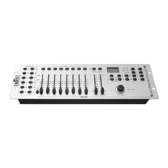
Page 5: Product Overview (Front)
Pile Up / Chase LED Joystick Generally used to control the pan and tilt movement of a fixture Mode button DMX-50A User Manual 22 23 Introduction Revised: 2006-04-24 15:26:16... -
Page 6: Product Overview (Rear Panel)
May be used to correct signal polarity DMX output connector DMX control signal DMX input connector Used to transfer programmed data between 2 controllers DC Input jack Main power feed ON/OFF power switch Turns the controller on and off DMX-50A User Manual Introduction Revised: 2006-04-24 15:26:16... -
Page 7: Common Terms
Shutter is a mechanical device in the lighting fixture that allows you to block the lights path. It is often used to lessen the intensity of the light output and to strobe. Patching refers to the process of assigning fixtures a DMX channel or.. DMX-50A User Manual Revised: 2006-04-24 15:26:16 Introduction... -
Page 8: Operating Instructions
FI XT UR E AD D R E S S IN G The DMX-50A is programmed to control 20 channels of DMX per fixture, therefore the fixtures you wish to control with the corresponding “SCANNER” buttons on the unit, must be spaced 20 channels apart. -
Page 9: Physical Fader Assignment
# 2. Release SCANNER button # 1 first before releasing SCANNER button # 2. All SCANNER LED indicators will flash to confirm successful copy. DMX-50A User Manual Operating Instructions You can re-assign the DMX channel to all controller fader channels. Notes All physical faders can be re-assigned to output on a different DMX channel. -
Page 10: Reverse Channel Output
Either ALL CH (all channels) or ONLY X/Y (Pan & Tilt only) Press MODE and TAP DISPLAY to save settings. All LEDS will blink to confirm. DMX-50A User Manual Operating Instructions Notes You can permanently reverse the output of any given channel on the controller. -
Page 11: Operation
Press the TAP DISPLAY button to view the step number on the display. Press the BANK UP/DOWN buttons review all scenes in the chase. DMX-50A User Manual Operating Instructions Notes All changes made while in Manual Mode are temporary and will not be recorded. -
Page 12: Programming
CR E AT E A S C E N E A scene is a static lighting state. Scenes are stored in banks. There are 30 bank memories on the controller and each bank can hold 8 scene memories. The DMX-50A can save 240 scenes total. Action Press the PROGRAM button until the LED blinks. -
Page 13: Check Program
Use BANK UP/DOWN buttons to select the destination PROGRAM bank. Press the MUSIC BANK COPY button to execute the copy. All LEDs on the controller will blink. DMX-50A User Manual Operating Instructions Notes Notes Deselect Blackout if LED is lit. -
Page 14: Chase Programming
Press the TAP DISPLAY button to switch the LCD display to steps. Review each scene/step individually by using the BANK UP/DOWN buttons. DMX-50A User Manual Operating Instructions Notes Notes The time between 2 taps will set the chase speed (up... -
Page 15: Edit Chase (Copy Bank Into Chase)
SCENE. Press the SCENE button that corresponds to the scene to be inserted. Press MIDI/REC button to insert the scene. All LEDs will blink. DMX-50A User Manual Operating Instructions Notes Notes Notes I.e. To insert a scene between Steps 05 and 06 navigate using BANK buttons until the display reads STEP05. -
Page 16: Delete A Scene In A Chase
Action Turn OFF controller. Press and hold the BANK DOWN button and the AUTO DEL button while turning ON the controller. All LEDs will blink. DMX-50A User Manual Operating Instructions Notes Remember that we use scene and steps interchangeably. Notes... -
Page 17: Scene Programming (Steps)
Press and hold the AUTO DEL button. Press the SCENE button that corresponds to the scene you want to delete. All LEDs will blink. DMX-50A User Manual Operating Instructions Notes I.e. To insert a scene between Steps 05 and 06 navigate using BANK buttons until the display reads STEP05. -
Page 18: Delete All Scenes
CHASE you would like to run simultaneously. BL AC KO UT The Blackout button brings all lighting output to 0 or off. DMX-50A User Manual Operating Instructions Notes CAUTION! This process is irreversible. All scenes with data will be set to 0. -
Page 19: Midi Operation
Chase 6 BLACKOUT Data Transfer It is possible to transfer the programs stored in one DMX-50A controller to another. Connect from the DMX output of the programmed controller to the DMX input of the other. Action Source unit: Turn unit Off, press and hold SCANNER buttons 2, 3 and SCENE button 1 then turn unit back On. -
Page 20: Appendix
XLR male to female connectors. The shield connection is pin 1, while pin 2 is Data Negative (S-) and pin 3 is Data positive (S+). CHAUVET carries 3-pin XLR DMX compliant cables, DMX-10 (33’), DMX-4.5 (15’) and DMX-1.5 (5’) -
Page 21: Returns Procedure
Package must be clearly labeled with a Return Merchandise Authorization Number (RA #). Products returned without an RA # will be refused. Call CHAUVET and request RA # prior to shipping the fixture. Be prepared to provide the model number, serial number and a brief description of the cause for the return. -
Page 22: Dmx Dipswitch Quick Reference Chart
27 59 91 123 28 60 92 124 29 61 93 125 30 62 94 126 31 63 95 127 Dip Switch Position DMX-50A User Manual DMX Address Quick Reference Chart Dip Switch Position DMX Address Appendix Revised: 2006-04-24 15:26:16... -
Page 23: General Troubleshooting
Remote does not work Make sure connector is firmly connected to device Stand alone mode All Chauvet lighting fixtures featuring stand-alone functions do not require additional settings, simply power the fixture and it will automatically enter into this mode DMX-50A User Manual... -
Page 24: Technical Specifications
Data pin configuration ...pin 1 shield, pin 2 (-), pin 3 (+) Protocols...DMX-512 USITT ORDERING INFORMATION DMX-50A Controller ... DMX-50A EC DECLARATION OF CONFORMITY We declare that our products (lighting equipments) comply with the following specification and bears CE mark in accordance with the provision of the Electromagnetic Compatibility (EMC) Directive 89/336/EEC.
Need help?
Do you have a question about the DMX-50A and is the answer not in the manual?
Questions and answers