
Related Manuals for Chauvet DMX-55 DMX


Summary of Contents for Chauvet DMX-55 DMX
-
Page 1: User Manual
DMX-55 DMX Controller USER MANUAL Chauvet, 3000 N 29 Ct, Hollywood, FL 33020 U.S.A (800) 762-1084 – (954) 929-1115 FAX (954) 929-5560 www.chauvetlighting.com... -
Page 2: Table Of Contents
ABLE OF ONTENT BEFORE YOU BEGIN ... 3 ... 3 HAT IS INCLUDED ... 3 NPACKING NSTRUCTIONS ... 3 AFETY NSTRUCTIONS INTRODUCTION... 4 ... 4 EATURES ... 4 ENERAL VERVIEW ) ... 5 RODUCT VERVIEW FRONT ) ... 6 ONNECTION IAGRAM REAR LCD D... -
Page 3: Before You Begin
Do not operate this device under 113° F ambient temperature conditions. Caution! There are no user serviceable parts inside the unit. Do not open the housing or attempt any repairs yourself. In the unlikely event your unit may require service, please contact CHAUVET. DMX-55 User Manual 2006-01-11 11:59:07... -
Page 4: Introduction
NTRODUCTION Features Universal DMX-512 Controller 240 scene memory 192 DMX channels of control Polarity selector Fog control button Strobe 3 space 19" rack or table top mount Removable rubber edge guard Midi compatible ... -
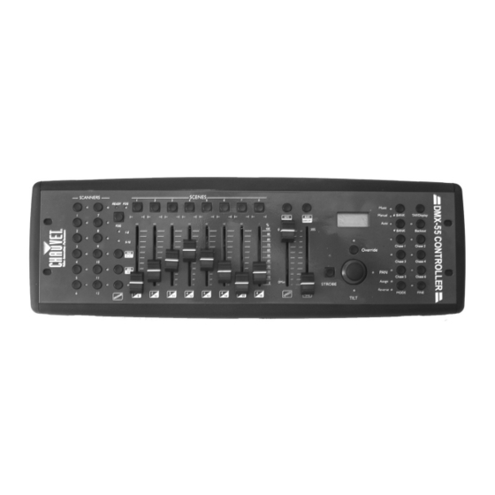
Page 5: Product Overview (Front)
This will adjust the hold time of a scene or a step within a chase Fade-Time fader Also considered a cross-fade, sets the interval time between two scenes in a chase Fog button Built in Chauvet fog controller Strobe button Built in Chauvet strobe controller Override button... -
Page 6: Connection Diagram (Rear)
DMX output connector DMX control signal DC Input jack Main power feed Strobe connector Chauvet Mono Strobe ¼” connector for built in strobe controller ON/OFF power switch Turns the controller on and off Fog connector Chauvet fog controller IEC connector... -
Page 7: Common Terms
Common Terms The following are common terms used in intelligent light programming. Blackout is a state by where all lighting fixtures light output are set to 0 or off, usually on a temporary basis. DMX-512 is an industry standard digital communication protocol used in entertainment lighting equipment. -
Page 8: Operating Instructions
Plug in a compatible Chauvet Fogger to the AC Fog Machine Remote Controller connector. Plug in any Chauvet MONO strobes in a daisy like fashion using a ¼” mono phone cable. FI XT UR E P AT CH The DMX-55 is programmed to control 16 channels of DMX per fixture, therefore the fixtures you wish to control with the corresponding “SCANNER”... -
Page 9: Joystick Setup
FINE. The Assign LED will light. Use BANK and BANK buttons to select either Pan or Tilt. Use the TAP/Display button to switch between the first 8 available channels (8CH) and the second 8 (16CH). Press the button corresponding to the SCANNER button you wish to assign. -
Page 10: Deleting A Scanner's Dmx Channel Settings
DE L ET ING A S C AN N E R’ S DM X CH AN N E L S ET T ING S Action Press the Program button until the LED blinks. Hold the MODE button and press FINE. The Reverse LED will light. -
Page 11: Scene Programming
SC E N E P RO G R AM M ING ENT ER ING PRO G R AM M ING M O DE Press the Program button until the LED blinks. CR E AT E A S C E N E A scene is a static lighting state. -
Page 12: Copy Scanner Settings
CO PY SC AN N E R S ET T ING S This operation allows the user to copy the programming state of one scanner to another. This is especially useful when both scanners are of the same type. Action Hold and maintain the Scanner button to copy. -
Page 13: Chase Programming
Tap the MIDI/Rec button. Use BANK and BANK buttons to select the bank to copy to. Tap the Music/Bankcopy button to execute the copy. To exit programming mode press the Program button until the LED turns off. Chase Programming A chase is created by using previously created scenes. -
Page 14: Add A Step
AD D A ST E P Action Press the Program button until the LED blinks. Press the corresponding button to the chase you wish to add a step to. Press the TAP/Display button so that the LCD display shows the current step. Use the ... -
Page 15: Delete All Chases
DE L ET E AL L C H AS E S Action With the power off, press and hold the AUTO/Del and BANK buttons. Turn controller back on and all chases will be cleared. Playback (Scenes) M ANU AL R UN SC EN E When power is first turned ON, the controller will be in manual scene mode. -
Page 16: Playback (Chases)
Playback (Chases) M ANU AL R UN C H AS E S This function allows the user to manually step through each individual step in a chase. Action When the power is first turned on the controller enters manual mode automatically. -
Page 17: Midi Operation
Midi Operation The controller will only respond to MIDI commands on the MIDI channel which it is set to full stop. All MIDI control is performed using Note on commands. All other MIDI instructions are ignored. To stop a chase, send the blackout on note. Action ... -
Page 18: Appendix
XLR male to female connectors. The shield connection is pin 1, while pin 2 is Data Negative (S-) and pin 3 is Data positive (S+). CHAUVET carries 3-pin XLR DMX compliant cables, DMX-10 (33’), DMX-4.5 (15’) and DMX-1.5 (5’) -
Page 19: Maintenance
Package must be clearly labeled with a Return Merchandise Authorization Number (RA #). Products returned without an RA # will be refused. Call CHAUVET and request RA # prior to shipping the fixture. Be prepared to provide the model number, serial number and a brief description of the cause for the return. -
Page 20: General Troubleshooting
Remote does not work Make sure connector is firmly connected to device Stand alone mode All Chauvet lighting fixtures featuring stand-alone functions do not require additional settings, simply power the fixture and it will automatically enter into this mode DMX-55 User Manual... -
Page 21: Technical Specifications
Data pin configuration ...pin 1 shield, pin 2 (-), pin 3 (+) Protocols...DMX-512 USITT ORDERING INFORMATION DMX-55 DMX Controller...DMX-55 EC DECLARATION OF CONFORMITY We declare that our products (lighting equipments) comply with the following specification and bears CE mark in accordance with the provision of the Electromagnetic Compatibility (EMC) Directive 89/336/EEC.
Need help?
Do you have a question about the DMX-55 DMX and is the answer not in the manual?
Questions and answers