Table of Contents
Advertisement
Quick Links
Startup
Operations
Maintenance
Accessories
Made in
Germany
OPERATING MANUAL
Read through this operating manual carefully be-
fore starting the machine.
HYDRAULIC LOG
SPLITTER
HS 71
Südharzer Maschinenbau GmbH
Helmestraße 94 ∙ 99734 Nordhausen/Harz
Zentrale:
Internet: www.bgu-maschinen.de
e-mail: info@bgu-maschinen.de
49(0)3631/6297-0 ∙ -111
+
Advertisement
Table of Contents

Related Manuals for BGU HS 71


Summary of Contents for BGU HS 71
- Page 1 OPERATING MANUAL Read through this operating manual carefully be- fore starting the machine. HYDRAULIC LOG SPLITTER Startup Operations Maintenance HS 71 Accessories Made in Germany Südharzer Maschinenbau GmbH Helmestraße 94 ∙ 99734 Nordhausen/Harz Zentrale: 49(0)3631/6297-0 ∙ -111 + Internet: www.bgu-maschinen.de...
-
Page 2: Table Of Contents
10.1 Noise emissions 11. Circuit diagram 12. Overview of residual risk 12.1 Prevention of mechanical dangers 12.2 Prevention of electrical dangers 13. Problems, causes and solutions 14. Warranty 15. Guarantee 16. HS 71 parts list 17. EC declaration of conformity... -
Page 3: Introduction
The hydraulic log splitter is available in the following variants: HS 71 (400V), splitting force 7 t HS 71 (230V), splitting force 6 t The log splitters are equipped with mechanical two-handed controls. - Page 4 It is also essential that the carrier (driver) countersign. If the carrier refuses to confirm the transport damages, the best course of action is to refuse receipt as a whole and notify us about it immedia- tely. Without a direct note on the bill of lading, any subsequent claims will not be recognized by the carrier nor the insurer of the transport.
-
Page 5: Product Overview
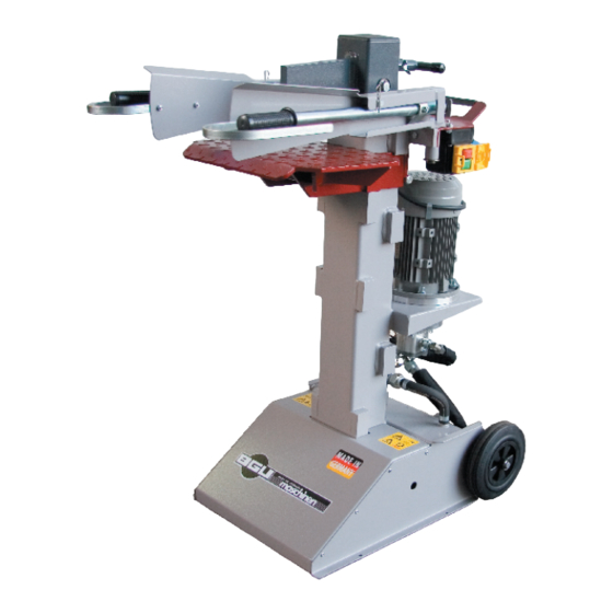
PRODUCT OVERVIEW Cross splitter Cross splitter Transport handle Guard bracket uard bracket Operating arms Table Switches- Motor Splitting column Wheels Stand... -
Page 6: Warning And Safety Pictograms
WARNING AND SAFETY LABELS 4. "pmax 200 bar" label for 230V "pmax 220 bar" label for 400V This label displays the max. operating pressure. -
Page 8: Safety Instructions
SAFETY INSTRUCTIONS Servicing, setup, maintenance and cleaning as well as trans- porting the machine may only be performed with the motor turned off and machine parts at a standstill. In order to minimize hazards and avoid damage, it is essential that the instructions regarding operation, assembly, maintenance, repair, malfunctions and similar are complied with. -
Page 9: Intended Use
4.1 Intended use The log splitter is designed for operation by 1 person. One machi- ne may never be operated by two or more persons. The „HS 71“ log splitter is intended solely for splitting firewood into smaller pieces in the direction of the grain. -
Page 10: Operation
BEDIENUNG 5.1 Mounting guard brackets Before using the log splitter the first time, the guard brackets (1) must be mounted onto the operating arms (see Fig. 1). For transport reasons these are only pre-mounted to the operating arm with one screw (2). -
Page 11: Checking The Two-Handed Controls
The control valve is set at the manufacturing plant; further ad- justments may not be attempted. 5.4 Checking the two-handed controls Log splitters are equipped with mechanical two-handed controls. The purpose of this is to ensure that the operator has no way to reach in- to the splitting area when working with the machine (see Fig.4). -
Page 12: Safety Instructions
5.6 Remarks concerning safety The log splitter must be set up on a firm and even surface. The work site must be kept free of wood scraps and obstacles (trip- ping hazards). Grit/sand is to be strewn on slippery and slick areas. -
Page 13: Adjusting The Table
5.8 Adjusting the table Logs ranging from 550 mm to 1065 mm can be easily split by adjus- ting the splitting table. The table can be adjusted to three heights, wi- thout the need for tools. To adjust the table, unscrew the wing nut (9; Fig.7) on the table mount/column and remove the bolt from the hole. -
Page 14: Working With The Wood Clamps
5.9 Working with the wood clamps Wood clamps (12) are attached to the operating arms to hold wood in place during the splitting operation (see Fig. 10). Because of the attached pressure springs (13), the wood clamps can adapt variably to logs of any size (see Fig. 10). The log must be aligned centrally in the wood clamps to ensure opti- mum functionality and proper splitting. -
Page 15: Transporting The Machine
TRANSPORTING THE MACHINE On electrically-powered machines, always remove the power plug before changing locations. It is very easy to transport the log splitter. An axle with two wheels is attached at the back. To transport the log splitter, tip it backward slightly until the wheels are touching the ground (see Fig.11). -
Page 16: Cross Splitter And Splitting Wedge Expander As Accessories
7. CROSS SPLITTER AND SPLITTING WEDGE EXPANDER AS ACCESSORIES Available as accessories* for our log splitters are a cross splitter and a splitting wedge expander (as additional purchases). The cross splitter splits the firewood into 4 parts in one operation. The splitting wedge expander allows improved and faster splitting of the wood. -
Page 17: Maintenance And Servicing Work
MAINTENANCE AND SERVICING WORK Please perform maintenance, servicing and cleaning only after the machine has been turned off (pull plug out of so- cket) and machine parts are at a standstill. 8.1 Regular maintenance tasks The following tasks are to be performed as necessary and/or on a re- gular basis: •... -
Page 18: Guides In The Splitting Column
8.3 Guides in the splitting column If squeaking sounds can be heard while running the log splitter, it is necessary to grease the polyamide guides in the splitting column tracks. A standard commercially-available grease can be used for this. The squeaking sounds should cease after doing this. After the polyamide guides have worn out, if the splitting column be- gins showing signs of excessive play to the column tracks, the polya- mide guides must be replaced. -
Page 19: Decommissioning And Disposal
9. DECOMMISSIONING AND DISPOSAL When the machine has reached a condition that it cannot be used anymore and must be scrapped, it is necessary to deactivate and dis- mantle it. This means that it must be converted into a state in which it cannot be used anymore for the purpose for which it was constructed. -
Page 20: Technical Specifications
10. TECHNICAL SPECIFICATIONS Technical specifications Unit 230 V 400 V Splitting height 550/750/1065 550/750/1065 Ram stroke Min. wood diameter Max. wood diameter Splitting force* Max. operating pressure Motor power rating P1 Nominal current 13,1 Speed 2660 2840 Rated voltage Backup fuse Total height, extendet 1570 1570... -
Page 21: Circuit Diagram
11. CIRCUIT DIAGRAM Work on the electrical system of the machine may only be car- ried out by a qualified electrician. For electrically-operated splitter machines use a portable residual cur- rent device (PRCD) if the residual current device (RCD) in the power supply does not have a nominal residual current of a max. -
Page 22: Overview Of Residual Risk
12. OVERVIEW OF RESIDUAL RISK 12.1 Prevention of mechanical dangers All dangers stemming from moving parts (splitting wedge) are mi- nimized by the two-handed controls. It is impossible to operate the machine when one operating arm is constantly clamped in the lower position. -
Page 23: Problems,Causes And Solutions
13. PROBLEMS,CAUSES AND SOLUTIONS Fault Cause Solution Splitting wedge does - The direction of rotation of the motor - Check rotation direction not travel out - Insufficient hydraulic oil - Fill up Splitting wedge does - See above - See above not retract Splitting wedge has - Insufficient hydraulic oil... -
Page 24: Guarantee
15. GARANTIE The guarantee period for SÜMA (Südharzer Maschinenbau GmbH) products in cases of exclusively private use is 24 months and, in ca- ses of commercial or professional use or use as rental equipment, 12 months from the shipment date. The statutory warranty is unaffected by this guarantee. -
Page 25: Hs 71 Parts List
16. PARTS LIST HS 71 Product overview, cpl. 5 Splitting column, cpl. 2 Activation rod, cpl. 3 Hydraulic cylinder, cpl. 1 Control arm, 4 Motor and pump, cpl. 7 Table cpl. 6 Stand, cpl. - Page 27 Item Name Part. No. Dimensions Control arm, cpl. Handle 52110 32302 Hex nut, self-locking 51607 Clamp 18854 Pressure spring 54413 Spring receptacle 51202 Clamp rod, g. 13657 Washer 51648 Hex screw 51398 M 8x45 Spring washer 51234 20x36,6x3 Control arm, left, g. 32329 Guard bracket 18282...
- Page 28 HS 71 2 Activation rod, Betätigungsrohr, kpl. cpl.
- Page 29 Item Name Part No. Dimensions Activation rod, cpl. Hex screw 51444 M 8x20 Spring washer 51706 Washer 51648 Control rocker 32298 Activation rod, g.. 32297 Hex nut 51591 Hex nut, self-locking 51606 Cap nut 11977 Spring washer 51193 Hex screw 51437 M 6x55 Cable sleeve...
- Page 30 HS 71 3 Hydraulic cylinder, Hydraulikzylinder, kpl. cpl.
- Page 31 Item Name Part No. Dimensions Hydraulic cylinder, cpl. Hydraulic cylinder 53019 Spring washer 51234 20x36,6x3 Upper fastening bolt 13561 Lower fastening bolt 11959 Item Name Part Dimensions Hydraulic hose and valve Hydraulic hose 54544 1SN 16-175 lg Hydraulic hose 52737 2SN 10-390lg Hydraulic hose 55124...
- Page 33 Item Name Part No. Dimensions Motor with pump, cpl. Motor 50751 230 V Motor 52028 400 V Cylinder head screw 51365 M 10x30 Spring washer 51707 Washer 51649 10,5 Clutch 53007 Cylinder head screw 51363 M 10x25 Pump bearer 50580 Hex nut, self-locking 51608 M 10...
- Page 34 HS 71 Spaltsäule, kpl. 5 Splitting column, cpl.
- Page 35 Item Name Part No. Dimensions Splitting column, cpl. Splitting column, g. 16016 Wing bolt 51263 M 8x20 Dip-molded cap 51041 19x25 Lamellar plug 50206 100x100x4 Threaded rod 51412 M 8x16 Bottom guide 53058...
- Page 36 6 Stand, cpl.
- Page 37 Item Name Part No Dimensions Stand, cpl. Stand, g. 32285 Wheel 52565 Washer 51652 Spring washer 51233 16x28,2x2,3 Axle 18864 Fillister head screw 53109 7380 M 8x10 Top guide 16070 Hex nut 51592 Hex screw 51449 M 8x28 Washer 51648 Hex nut, self-locking 51607 Cylinder head screw...
- Page 38 HS 71 7 Table, Tisch, kpl. cpl. Item Name Part No Dimensions Table, cpl. Table, g. 32295 Wing nut 54194 M 12 Hex screw 54317 M 12x160...
-
Page 39: Ec Declaration Of Conformity
This declaration will become invalid if any changes are made to the machine which were not agreed to by us. Hydraulic log splitter Name of the machine: HS 71 (400V) Type: HS 71 (230V) Hersteller-Nr.: Refer to type plate... - Page 40 Subject to changes Südharzer Maschinenbau GmbH Helmestraße 94 ∙ 99734 Nordhausen/Harz Service-Tel. 03631/6297-104 ∙ Fax 03631/6297-111 Form: 2432 01.07.2016 - Rev. A Internet: www.bgu-maschinen.de Form: 2438 01.07.2016 - Rev. A e-mail: info@bgu-maschinen.de...
Need help?
Do you have a question about the HS 71 and is the answer not in the manual?
Questions and answers