Table of Contents
Advertisement
Quick Links
Advertisement
Table of Contents

Related Manuals for Smart Storm USM UV254


Summary of Contents for Smart Storm USM UV254
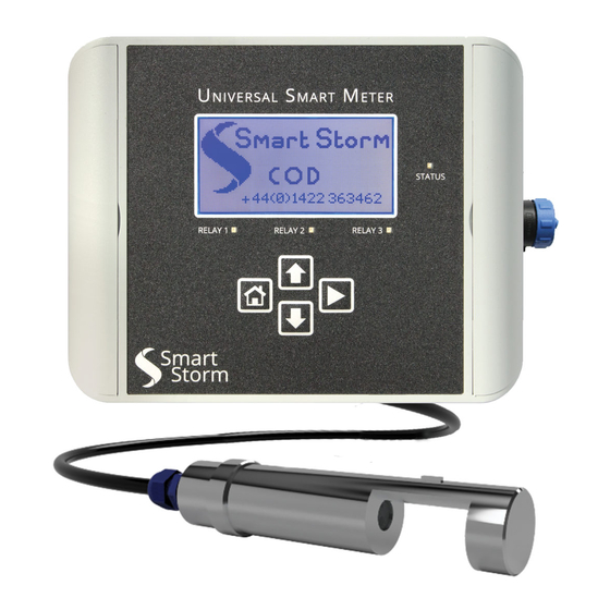
- Page 1 V 2.0 USM UV254 METER INSTRUCTION MANUAL 1 Lon Cae Darbi Cibyn Industrial Estate Llanberis Rd, Caernarfon Gwynedd, LL55 2BD Tel: +44 (0)1422 363462 Enquiries@smartstormgroup.com Web: www.smartstormgroup.com UNIVERSAL SMART METER COD METER USER MANUAL v2.0.docx page 1 of 50...
-
Page 2: Table Of Contents
Contents 1. Specification......................5 2. General Information..................... 6 2.1. Safety information ..................6 2.2. Use of hazard information ................7 2.3. Precautionary labels ..................7 2.4. Wiring and Handling Precautions ..............8 3. Turning ON the Environmental USM..............9 3.1. - Page 3 4.12. Set Date and Time................... 34 4.13. Screen Save Mode.................. 34 4.14. Logger Interval..................35 4.15. Engineer Menu..................36 4.16. WHAT IS UVA AND UVT? ............... 37 5. Pathlength and UVA/UVT .................. 37 5.1. UVA CALIBRATION..................38 5.1.1.
- Page 4 List of Figures Figure 3-1 Relay Board Connections ............... 11 Figure 3-2 Smart Storm Screen ................12 Figure 3-3 Home Screen ..................12 Figure 4-1 USM ......................13 Figure 4-2 Password Screen..................14 Figure 4-3 Configuration Menu Screen ..............14 Figure 4-22 Digital Probe Detect.
-
Page 5: Specification
Specification. Universal Smart Meter – level Meter Specifications Inputs UV254 probe. -5 - 50 °C Temperature Range Graphic LCD 124x64 dots Negative Display Blue 3 SPDT, 5A Relays 4 – 20 mA galvanic isolated Current Output 100 – 240 VAC 50/60Hz. Switched- Mains Supply mode power supply 12V or 24V... -
Page 6: General Information
However, Smart Storm assumes no responsibility for any inaccuracies that may be contained in this manual. In no event will the Smart Storm be liable for direct, indirect, special, incidental, or consequential damages resulting from any defect or omission in this manual, even if advised of the possibility of such damages. -
Page 7: Use Of Hazard Information
2.2. Use of hazard information DANGER Indicates a potentially or imminently hazardous situation which, if not avoided, could result in death or serious injury. WARNING Indicates a potentially or imminently hazardous situation which, if not avoided, could result in death or serious injury. CAUTION Indicates a potentially hazardous situation that may result in minor or moderate injury. -
Page 8: Wiring And Handling Precautions
NOTICE Delicate internal electronic components can be damaged by static electricity, resulting in indeterminate instrument performance or eventual failure. Smart Storm recommends taking the following steps to prevent ESD damage to your instrument: • Before touching any instrument electronic components (such as printed circuit cards and the components on them) discharge static electricity from your body. -
Page 9: Turning On The Environmental Usm
The instrument is designed to read a range of environmental measurements associated with the wastewater industry with an optional on-board data logger for recording and downloading to the Smart Storm Inquisitor data viewing platform. Three relays (with LED indication) and two 4-20mA outputs are provided to control ancillary equipment and the meter can be interrogated remotely using Modbus RTU (RS485) communication. - Page 10 ➢ CONN6 - bottom row provides the RS485 connections for the connection of a digital probe. The power connections for the probes are also available. ➢ CONN7 – provides the connection for the ISE probe including a PT100 temperature input and a connection for grounded probes. UNIVERSAL SMART METER COD METER USER MANUAL v2.0.docx page 10 of 50...
-
Page 11: Figure 3-1 Relay Board Connections
Figure 3-1 PCB Board Connections UNIVERSAL SMART METER COD METER USER MANUAL v2.0.docx page 11 of 50... -
Page 12: Turn On
3.3. Turn On. When the unit is turned on a splash screen (Figure 1) will be shown detailing the contact details of Smart Storm. Figure 3-2 Smart Storm Screen This will be followed automatically by the Home Screen (Figure 2). -
Page 13: Configuring The Usm
Configuring the USM. Figure 4-1 USM The USM is configured using the four push buttons. Button Action Scroll Right or Enter Scroll up, Increment Numbers Scroll down, Decrement Numbers Return to previous menu level or to Home Screen and Abort Table 4-1 Key Functionality UNIVERSAL SMART METER COD METER USER MANUAL v2.0.docx page 13 of 50... -
Page 14: Configuration Menu Access
4.1. Configuration menu access. The unit is configured through the MENU page which is password protected. From the Home Screen, press button to access the PASSWORD page. Figure 4-2 Password Screen. buttons to select the desired digit at each location and press button to select the next digit. -
Page 15: Configuration Menu
USM to the Home Screen. The ENGINEERING menu contains settings which should only be changed by Smart Storm and requires an additional password. N.B. When the Configuration Menu is entered, the status of the relays and the 4-20mA output are not updated. -
Page 16: Digital Probe Set Up For Uv254
4.3. Digital Probe SET UP for UV254. Use the buttons to select the DIGITAL PROBE and press confirm the selection. 4.3.1. Detect Probe. Before the probe can be configured or calibrated it must first be detected. Use the buttons to select the DETECT PROBE and press to confirm the selection. -
Page 17: Display Parameters
4.3.2. Display Parameters. The main Digital Probe Display Screen shows two of up to four parameters measured by the probe in large font. The default settings after a probe is detected are the first two registers of the probe. Probe Param 1 Param 2 Param 3... -
Page 18: What Is Cod
If the COD is too high, then the receiving waters can be stripped of their oxygen levels and damage aquatic life. The figure below shows the correlation of UV254 absorption and COD as measured with the smart storm UV254 probe. COD Measurements COD mg/L Figure 4-7 COD diagram measurements. -
Page 19: Cod Calibration
4.3.2. COD Calibration. • Been in the DIGITAL PROBE settings as below, scroll down to “PROBE CALIBRATION” and validate with the follow key icon Use the key to scroll down to the probe calibration option and validate your button. Scroll down to UVA – Parameters to calibrate selection using the COD/BOD/TOC/DOC. - Page 20 First select the high point by using the button. Now enter you value by using the buttons and validate your input to start the high point calibration process with your probe into the COD solution. This is where the maximum concentration is stored. After the completion of the high point calibration, restart the above step again but with the low point calibration option to enable two points calibration.
- Page 21 The main advantage the UV254 surrogate measurement has over the above is speed of measurement. The Smart Storm online UV254 can take an input from these analysers, allowing the combine system to provide real time calibrated measurements. The calibration procedure on the USM is the same as the COD calibration on the previous page.
-
Page 22: Digital Probe Calibration
The main advantage the UV254 surrogate measurement has over the above is speed of measurement and operational cost. The Smart Storm online UV254 can be purchased with a filter before the flow cell to remove the suspended organic material, and allow for better surrogate measurements of DOC. - Page 23 Figure 4-8 Probe Calibration Mode Select the parameter your reading before making any modification. Use the Up and Down key to browse the selection. Figure 4-9 Gain Correction Probe Selection From the screen below, use the up and down keys to enter the value for option. USM value is the actual reading of the USM and the lab value is the result from the lab if any laboratory measurement were used.
-
Page 24: Message Set Up
Figure 4-10 Gain Correction Mode SAVE your new gain factor for the result to the displayed both in the logger and on the screen. 4.4. Message SET UP. The USM can be set to compensate for changes in temperature of the measured liquid. -
Page 25: Modbus Bms Set Up
Figure 4-11 Temperature Mode Use the buttons to select the Temperature Mode (MANUAL, AUTO, OFF), press to enter and confirm that a change of Mode is to be save. If a Digital probe is detected an additional option is available (DIGITAL). This does not provide any compensation but displays the digital temperature on the Home Screen. -
Page 26: 4-20Ma Set Up
Parity: Even, Odd, None. Protocol: RTU, ASCII (ASCII is not implemented on the current software release – Please contact Smart Storm if it is a requirement). After configuring all the parameters press Home key and confirm the data is to be saved. -
Page 27: Figure 4-28 4-20Ma Status Screen
Figure 4-14 4-20mA Status Screen. Use the buttons to select Output channel to be configured and press to confirm the selection. Figure 4-15 4-20mA Set UP Screen. With the cursor pointing at Status, the button can be used to toggle the channel between ENABLED and DISABLED. -
Page 28: Typical 4-20Ma Set Up For Uv254 Balancing
Figure 4-16 4-20mA Parameter Selection. The cursor will change from to a solid triangle ►. The buttons are now used to change the value of the selected parameter. When the correct button and the cursor will return to a ˃ and the value is entered press the buttons will return to parameter select. -
Page 29: 4-20Ma Test
Similarly, if the pH goes above 7.9 Channel 2 will turn on the Acid dosing with the maximum dosing at pH 8.5. 4.7. 4-20mA Test. The 4-20mA outputs can be controlled directly using the 4-20mA Test screen. This can be used to check the outputs are working correctly or to directly control the outputs independently of the parameter they are monitoring. -
Page 30: Figure 4-33 Change The Ma Output
A solid triangle ► will appear beside the mA value. The buttons are now used to change output in 1mA steps. Figure 4-19 Change the mA Output. After testing the channel press to return to the output select. The 4-20mA output can be tested directly using a multi-meter with a mA current input or by connecting a resistor across the output and measuring voltage (with a 100 ohm resistor 4mA will give a reading of 100 * 0.004 = 400mV and 20mA will give a reading of 100 * 0.02 = 2V). -
Page 31: Relay Set Up
4.8. Relay Set up. The USM provides 3 relay outputs which can be wired as Normally Open or Normally Closed. The relay is active in the configured position. The relays can be controlled by the Analogue (ISE) probe or either of the two enabled Digital probe measurements. -
Page 32: Figure 4-36 Relay Set Up Parameter Change
• The Mode is only selectable if a Digital Probe is connected and configured. • The Param is only selectable when Mode is set to DIGITAL. • The values of Param are limited to the parameters selected when configuring the DIGITAL probe. To change a parameter, move the cursor to the parameter to be changed and press the button. -
Page 33: Relay Cleaning Cycle
4.9. Relay Cleaning Cycle: Relay 3 of the USM UV254 is used for the cleaning cycle where the reading will be ignored on the data sheet during that time. Setting up the Cleaning cycle involves frequency, duration, settle. The frequency is measured in hour with max as 24hours. -
Page 34: New User Password
4.11. New User Password. The default password on the USM is set to 0000. This can be changed by selecting the NEW USER PASSWORD and following the on-screen instructions. The new password will come into immediate operation once the it is saved, and the configuration menu exited. -
Page 35: Logger Interval
4.14. Logger Interval. Some versions of the USM are available with a build in Data Logger. The measurements can be recorded and displayed using Smart Storm’s Inquisitor Software. The interval at which the measurements are logged can be set on the Logger Interval Screen. -
Page 36: Engineer Menu
4.15. Engineer Menu. The ENGINNERING MENU is used for the setting of factory calibrated parameters and should not be accessed unless the user knows exactly what he/she is doing. From the Menu Screen, Use the buttons to step through the available interval options known as ENGINNERING MENU and press button to access the PASSWORD page. -
Page 37: What Is Uva And Uvt
This can be set to other values if necessary, such as abs/m. Smart Storm UV254 systems come in with different optical paths. The measurement of the absorption is converted to abs/cm no matter what size the optical path. Also,... -
Page 38: Uva Calibration
5.1. UVA CALIBRATION. Figure 5-42 ENGINEERING MENU. Use the buttons to select the UVA CALIBRATION and press confirm the selection. 5.1.1. UVA CALIBRATION SET UP. Before the probe can be configured or calibrated it must first be detected and insert into distilled water. Use the buttons to select the UVA CALIBRATION and press to confirm the selection. -
Page 39: Usm Display Screens
Figure 5-44 UVA CALIBRATION. Press to confirm the selection. The USM will save the data automatically after a few seconds before the probe sampling time starts. Figure 5-45 SAMPLING SCREEN Now, wait for the sampling time to reach 0 for the calibration to be successful. -
Page 40: Home Screen
6.1. HOME SCREEN. Figure 6-1 Home Screen. If an Analogue/ISE Probe is selected the Home Screen shows the probe type and the current measurement from the UV254 probe. The current date and time are displayed along with bar graphs to indicate the percentage output of the two 4-20mA channels. -
Page 41: Figure 4-45 Sampling Screen
RELAY2 & 3 STATUS SCREEN 4-20mA CHANNEL 1 STATUS SCREEN 4-20mA CHANNEL 2 STATUS SCREEN DATE AND TIME SCREEN COMMS CONFIGURATION SCREEN ABOUT USM SCREEN SMART STORM SPLASH SCREEN HOME UNIVERSAL SMART METER COD METER USER MANUAL v2.0.docx page 41 of 50... -
Page 42: Digital Probe Screen 1
6.2. Digital Probe Screen 1. The first Digital Probe Screen shows the values of the two parameters selected from the Digital Probe Display Params setting. Figure 6-4 Digital Probe Screen 1. If no probe is detected an error message (“Probe not detected”) will appear on the screen. - Page 43 Figure 6-6 Digital Probe Screen 3. If no probe is detected an error message (“Probe not detected”) will appear on the screen. UNIVERSAL SMART METER COD METER USER MANUAL v2.0.docx page 43 of 50...
-
Page 44: Relay Status Screens
6.4. Relay Status Screens. The USM has two relay screens which show the Set Up and state of the three relays. Relay Page 1 covers Relay 1 and Relay 2, whilst Relay Page 2 repeats Relay 2 and additional shows Relay 3. Figure 6-6 Relay Page 1. -
Page 45: 4-20Ma Screens
6.5. 4-20mA Screens. Figure 6-8 4-20mA Screen. The USM 4-20mA screen shows the current Set Up of the 4-20mA along with the current value (CUR) of the selected measurement and the mA output for the value of that measurement. A similar page is available for 4-20mA OUT2. 6.6. -
Page 46: Date And Time Screen
6.7. Date and Time Screen. The current date and time are displayed. Please ensure these values are correct as these settings are used by the logger. 6.8. Modbus Set Up Screen. Figure 6-10 Modbus Set Up Screen. The current setting for the Modbus BMS (Building Management System) are displayed on this screen. -
Page 47: Fault Finding
Accuracy for the UV254 Probe: 1mm path 2mm path 5mm path 10mm path 20mm path 50mm path Parameter length in length in length in length in length in length in mg/L mg/L mg/L mg/L mg/L mg/L 0.08 0.04 0.04 0.04 Table 6-2 Accuracy Reading for UV254. -
Page 48: Appendices
Appendices. 8.1. APPENDIX A. ISE PROBES PROBE TYPE LIMITS NOMINAL NOMINAL SLOPE VALUE pH 0 – -59.16 mV/pH 0mV @ pH1 4 pH 7 -1000mV – REDOX 1000mV 0.02 ppm – 17000 Ammonia +59.16 mV/dec 0.9 ppm – Ammonium +59.16 mV/dec 350mV @ 9000 ppm 1000 ppm... -
Page 49: Appendix B. Modbus Registers
8.2. APPENDIX B. Modbus Registers The Modbus RTU uses the following format: SEND COMMAND START ADDRESS NUMBER OF BYTES CRC16 XXXX XXXX XXXX 01 – 240 0000 – 0018 READ 0004 or 0008 CRC16 REPLY COMMAND NUMBER OF BYTES VALUE CRC16 XXXXXXXX OR XXXX... -
Page 50: Declaration Of Conformity
BS EN61010-1 Low Voltage 1993 We also declare that the products: Named above are of UK origin and are manufactured and tested to Smart Storm internal quality standards defined in the company’s formal ISO9001:2015 quality manual. Dr John Duffy Managing Director UNIVERSAL SMART METER COD METER USER MANUAL v2.0.docx...
Need help?
Do you have a question about the USM UV254 and is the answer not in the manual?
Questions and answers