Sign In
Upload
Manuals
Brands
Smart Storm Manuals
Measuring Instruments
USM UV254
Smart Storm USM UV254 Manuals
Manuals and User Guides for Smart Storm USM UV254. We have
1
Smart Storm USM UV254 manual available for free PDF download: Instruction Manual
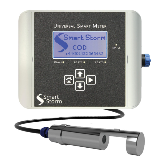
Smart Storm USM UV254 Instruction Manual (50 pages)
Brand:
Smart Storm
| Category:
Measuring Instruments
| Size: 3 MB
Table of Contents
Table of Contents
2
1 Specification
5
Table 1-1 Device Specification
5
2 General Information
6
Safety Information
6
Use of Hazard Information
7
Precautionary Labels
7
Wiring and Handling Precautions
8
3 Turning on the Environmental USM
9
UV254 Probes
9
Digital Probes
9
USM Connections
9
Figure 3-1 Relay Board Connections
11
Turn on
12
Figure 3-2 Smart Storm Screen
12
Figure 3-3 Home Screen
12
4 Configuring the USM
13
Table 4-1 Key Functionality
13
Figure 4-1 USM
13
Configuration Menu Access
14
Figure 4-2 Password Screen
14
Figure 4-3 Configuration Menu Screen
14
Configuration Menu
15
Digital Probe SET up for UV254
16
Detect Probe
16
Figure 4-22 Digital Probe Detect
16
Figure 4-23 Digital Probe Scan Result
16
Display Parameters
17
Figure 4-24 Display Digital Probe Parameters
17
Table 4-2 Digital Probe Parameters
17
What Is COD
18
COD Calibration
19
Digital Probe Calibration
22
Gain Factor Correction
22
Tss
22
Message SET up
24
Figure 4-25 Temperature Mode
25
Figure 4-26 MODBUS Setup
25
Modbus BMS SET up
25
4-20Ma SET up
26
Figure 4-27 MODBUS Parameter Select
26
Figure 4-28 4-20Ma Status Screen
27
Figure 4-29 4-20Ma Set up Screen
27
Figure 4-30 4-20Ma Parameter Selection
28
Figure 4-31 4-20Ma for UV Balancing
28
Typical 4-20Ma SET up for UV254 Balancing
28
4-20Ma Test
29
Figure 4-32 4-20Ma Testing
29
Figure 4-33 Change the Ma Output
30
Figure 4-34 Relay Status Screen
31
Figure 4-35 Relay Set up Screen
31
Relay Set up
31
Figure 4-36 Relay Set up Parameter Change
32
Figure 4-37 Relay Testing
33
Relay Cleaning Cycle
33
Relay Test
33
Figure 4-38 Time and Date Setting
34
Figure 4-39 Screen Saver Setting
34
New User Password
34
Screen Save Mode
34
Set Date and Time
34
Figure 4-40 Logger Interval Setting
35
Figure 4-42 Engineering MENU
35
Logger Interval
35
Engineer Menu
36
Figure 4-41 Password
36
What Is Uva and Uvt
37
5 Pathlength and UVA/UVT
37
Uva Calibration
38
Uva Calibration Set up
38
6 USM Display Screens
39
Home Screen
40
Figure 4-43 Logger Interval Setting
40
Figure 4-44 Calibrate UVA
40
Figure 5-1 Home Screen UV
40
Figure 5-2 Home Screen UV254 with Temperature
40
Figure 5-3 Digital Probe Only
40
Figure 4-45 Sampling Screen
41
Digital Probe Screen 1
42
Digital Probe Screen 2
42
Figure 5-4 Digital Probe Screen 1
42
Figure 5-5 Digital Probe Screen 2
42
Figure 5-6 Digital Probe Screen 3
42
Relay Status Screens
44
Figure 5-6 Relay
44
Figure 5-7 Relay
44
4-20Ma Screens
45
Slope Configuration Screen
45
Figure 5-8 4-20Ma Screen
45
Figure 5-9 Slope Configuration
45
Date and Time Screen
46
Modbus Set up Screen
46
About USM
46
UV254 Range
46
Figure 5-10 Modbus Set up Screen
46
7 Fault Finding
47
Table 6-1 UV254 Probe Range
47
Table 6-2 Accurancy Reading Range
47
Table 6-3 Fault Finding
47
8 Appendices
48
Appendix A. Ise Probes
48
APPENDIX B. Modbus Registers
49
Table 7-1Modbus Registers
49
9 Declaration of Conformity
50
Advertisement
Advertisement
Related Products
Smart Storm Universal Smart Meter
Smart Storm USI
Smart Storm AVOCET-9000
Smart Storm ISE METER
Smart Storm USI HYDROCELL 1
Smart Storm Categories
Measuring Instruments
Industrial Equipment
More Smart Storm Manuals
Login
Sign In
OR
Sign in with Facebook
Sign in with Google
Upload manual
Upload from disk
Upload from URL