Table of Contents
Advertisement
Quick Links
PROPER INSTALLATION IS IMPORTANT. IF YOU NEED ASSISTANCE, CONSULT A CONTRACTOR, ELECTRICIAN
OR TELEVISION ANTENNA INSTALLER (CHECK WITH YOUR LOCAL BUILDING SUPPLY, OR HARDWARE STORE
FOR REFERRALS). TO PROMOTE CONFIDENCE, PERFORM A TRIAL WIRING BEFORE INSTALLATION.
1
Feed the teminal lug end of the black and white wires through
one of the rubber boots and connect the lugs to the terminals on the
bottom of the wind speed sensor using the brass nuts provided. The polarity
does not matter. (Do NOT adjust the nuts that are already on the sensor).
RED
WIRE
4
5
GREEN
WIRE
BOOT
Slide the stub masts through the rubber boots and
insert the stub masts into the bottom of the sensors. Secure
with the cotter pins. Coat all wire connections with silicone
sealant and slip the boots over the sensors.
WIND DIRECTION
SENSOR
TERMINAL
#4
BOSS
TERMINAL #4
MUST ALIGN
WITH Z-MAST
ARM
Secure the sensors and stub masts to your antenna mast (not supplied) with
the two hose clamps. Align the wind-direction Z-mast arm to true North.
Radio Shack and similar stores have a selection of tall masts and roof
mounting brackets. Choose a mount that best suits your location and
provides at least eight feet of vertical clearance above objects on the roof.
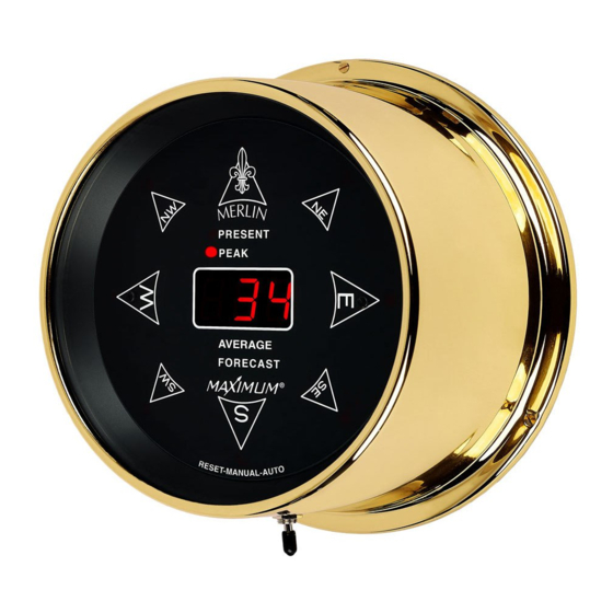
MERLIN
Determine where you are going to locate both the
rooftop sensors and the read-out.
Feed the terminal lug end of the red and green wires through the other
3
rubber boot. Connect the red wire to the terminal marked #4.
Connect the green wire to the terminal marked #5. The polarity MUST be
observed. Use the hex nuts provided. (Do NOT adjust the nuts that are
already on the wind direction sensor).
4A
When connecting the wind direction sensor
to the Z-mast, make certain that terminal #4
is aligned with the Z-mast arm. If the sensor
is not installed in this manner your wind
direction readings will be incorrect.
Samuel Barnett Boulevard
New Bedford, MA 02745
4
(508) 995-2200
2
WIND DIRECTION
WIND SPEED
SENSOR
SENSOR
COTTER
PIN
4
STRAIGHT
STUB MAST
BLACK & WHITE
BOOT
WIRES
5
BLACK AND WHITE
WIRES
BOOT
COTTER
PIN
Z-STUB
MAST
RED & GREEN
WIRES
HOSE
CLAMPS
Advertisement
Table of Contents
Troubleshooting

Related Manuals for Maximum MERLIN


Summary of Contents for Maximum MERLIN
- Page 1 MERLIN INSTALLATION PROPER INSTALLATION IS IMPORTANT. IF YOU NEED ASSISTANCE, CONSULT A CONTRACTOR, ELECTRICIAN OR TELEVISION ANTENNA INSTALLER (CHECK WITH YOUR LOCAL BUILDING SUPPLY, OR HARDWARE STORE FOR REFERRALS). TO PROMOTE CONFIDENCE, PERFORM A TRIAL WIRING BEFORE INSTALLATION. Determine where you are going to locate both the rooftop sensors and the read-out.
- Page 2 When Merlin first starts up it will perform a brief self-test and then go to the "Present" function mode. SCREW Reset all memory functions (see operating instructions). Resetting gives Merlin a fresh starting point for your reference. Samuel Barnett Boulevard New Bedford, MA 02745 (508) 995-2200...
- Page 3 IMPORTANT FACTS ABOUT YOUR MERLIN Peak Wind- When first powering up MERLIN, after long power outages, or when totally resetting, the Peak Wind direction LEDs will not function until at least 1 MPH wind has been recorded.
- Page 4 Setting the switch to Auto does not erase stored data. You do not need to time the 6 second reset time, MERLIN will blank out the display to indicate that the memory has been erased.
- Page 5 MERLIN TROUBLE SHOOTING (WIND DIRECTION) Perform the latch up corrections as previously detailed. The unit will now perform the self test, all LEDS will light NORMAL UNLATCH for about 3 seconds. If you did not have time to check that all LEDS light, repeat the procedure. This will cause the self test to start again.
- Page 6 MERLIN TROUBLE SHOOTING (WIND SPEED) VOLT-OHMETER FROM AC ADAPTER FROM ROOF TOP SENSORS BLACK AND WHITE WIRES IF THERE IS WIND..Disconnect the black and white wires from the back of the of the indicator and connect them to volt-ohmeter as shown. Set for low range AC Volts.
- Page 7 AC Adaptor: This instrument requires its own AC Adaptor. Due to the various power requirements of each Maximum instrument, attempting to run more than one instrument on a single adaptor could cause improper operation and/or damage to the instrument(s) thereby voiding your 5-year warranty.
Need help?
Do you have a question about the MERLIN and is the answer not in the manual?
Questions and answers