Advertisement
WARNING
CAUTION
CAUTION
ACTIVATE THE TRANSMITTER ONLY WHEN THE
DOOR / GATE IS IN FULL VIEW, FREE OF
OBSTRUCTION AND PROPERLY ADJUSTED. NO
ONE SHOULD ENTER OR LEAVE THE DOOR/ GATE
WHILE IN MOTION. DO NOT ALLOW CHILDREN TO
OPERATE THE REMOTE(S) OR THE DOOR/ GATE
CONTROL BUTTONS. DO NOT ALLOW CHILDREN
TO PLAY NEAR THE DOOR/ GATE.
The TriCode
TM
digital TC1 and TC2 transmitters are a
single-channel and dual-channel wireless radio control
designed for use with automatic garage/gate operators
and access control systems. All TriCode
be combined with Linear/Delta-3
TM
Stanley
radio products.
The TriCode
TM
radio format provides a potential of 1024
different digital codes. For Linear/Delta-3
products, 256 different digital codes are available. The
codes are set using a 10-position DIP switch system.
CAUTION:To avoid possibility of duplicating codes
in adjacent systems, all transmitters and receivers
should be re-coded prior to operation. Unless using
maximum number of codes the following four codes
should not be used:
· All DIP Switches ON
· All DIP Switches OFF
· DIP Switches alternating ON/OFF
· DIP Switches alternating OFF/ON.
Step 1 Locate Switch(s) and Connect Battery
Locate the DIP switch, configuration switch and battery
by sliding down access cover on front of the transmitter
case. DIP switch is numbered 1 through 10. The
configuration switch is located to the right of the DIP
switch (Refer to figures 1, 2, 3 and 4).
The battery is located below the switches. Connect the
battery connector to the 9V battery before programming
transmitter (Refer to figure 3).
TM
products may
TM
TM
, Multi-Code
, and
TM
compatible
SWITCH SETTINGS
WARNING
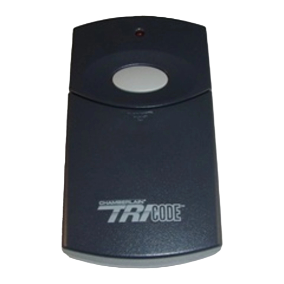
TriCode
Transmitters
TC1 Single Channel
Transmitter
U.S. Patent Pending
WARNING
This device complies with FCC Rules Part 15 and IC
Canada Rules and Regulations. Operation is subject to
the following two conditions: (1) This device may not
cause harmful interference and (2) this device must
accept any interference received, including interference
that may cause undesired operation.
F.C.C. rules prohibit adjustments to or modification of
receiver and/or remote control transmitter circuitry
except for changing the code setting and replacing
remote control transmitter battery. THERE ARE NO
OTHER SERVICEABLE PARTS.
Step 2 Set Transmitter Configuration Switch(s)
The TriCode
TM
Transmitter is factory set to Linear/Delta-
3
TM
position.
Using a pointed object set transmitter configuration
switch to desired setting (Refer to figure 1). On dual
channel transmitters the left button corresponds to the
top set of switches and the right button corresponds to
the bottom set of switches (Single Channel, Refer to
figure 3; Dual Channel, Refer to figure 4).
Step 3 Set Transmitter DIP Switch(s)
The TriCode
TM
Transmitter DIP switch(s) are factory set,
CH1 OFF (1-10) and CH2 ON (1-10).
Using a pointed object set transmitter DIP switch to
desired setting. For Linear/Delta-3
codes on switches 1 through 8. Switches 9 and 10 are
not used for Linear/Delta-3
either the "ON" or "OFF" setting.
Note: Switches in receiver must match the switches
in all transmitters used to operate the receiver.
Some older radios use toggle switches and it may
be difficult to determine 'ON' & 'OFF'. If so, try
reverse settings on the TriCode
TM
TC2 Dual-Channel
Transmitter
U.S. Patent Pending
TM
compatibility, set
TM
products, and can be in
TM
.
Advertisement
Table of Contents

Subscribe to Our Youtube Channel
Related Manuals for Chamberlain TC1


Summary of Contents for Chamberlain TC1
-
Page 1: Product View
CONTROL BUTTONS. DO NOT ALLOW CHILDREN TO PLAY NEAR THE DOOR/ GATE. The TriCode digital TC1 and TC2 transmitters are a single-channel and dual-channel wireless radio control designed for use with automatic garage/gate operators and access control systems. All TriCode... - Page 2 1-800-528-3536 HOURS 7:00 TO 3:30 p.m. (Mountain Std. Time) MONDAY Through SATURDAY OR CONTACT US THROUGH THE WEB AT WWW. CHAMBERLAINGROUP.COM © 2000, The Chamberlain Group, Inc. All Rights Reserved MULTI/ STANLEY (1 THRU 10) LINEAR/ DELTA-3 (1 THRU 8)
Need help?
Do you have a question about the TC1 and is the answer not in the manual?
Questions and answers