
Related Manuals for Haug HAUG

Summary of Contents for Haug HAUG
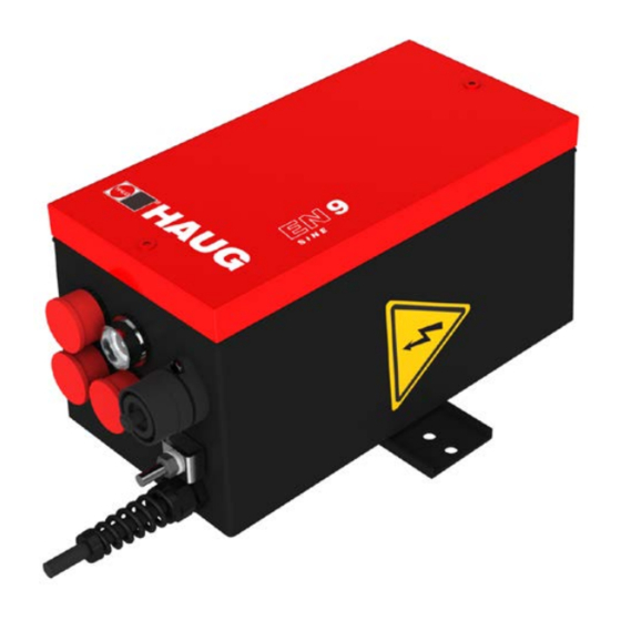
- Page 1 Operating instructions Discharging power pack EN 9 Sine UL Ident number: 01.7924.XXX (230 V), 01.7925.XXX (115 V), 01.7926.XXX (230 V), 01.7927.XXX (115V) Keep for future use! Static Line...
-
Page 3: Table Of Contents
Table of contents Operator instructions ..........4 Symbols used in operating instructions ......4 Symbols on the discharging power pack ......5 Safety ................6 Intended use ..............7 Product overview............8 Install ................9 Operate ..............14 Normal operation ............14 Operate over the signalling socket K1......15 5.2.1 Pulsing high voltage .......... -
Page 4: Operator Instructions
Operator instructions 1 Operator instructions Before installation and commissioning read these operating instruction in full. Always observe the safety instructions. These operating instruction is a part of the product; make sure you retain them for later use or subsequent owners. The discharging power pack is maintenance free and operationally safe when used as intended. -
Page 5: Symbols On The Discharging Power Pack
Operator instructions Never dispose of with household garbage. Caution, danger spot warning! 1.2 Symbols on the discharging power pack WARNING! High voltage ATTENTION! Only plug in/unplug the ionizing unit at the HV terminal when the discharging power pack is switched off. -
Page 6: Safety
Safety 2 Safety Only the persons authorized by the operator may carry out tasks on the discharging power pack. The installer must be a trained and qualified electrician and read the operating instructions in full. The operator must read the operating instructions in full. When working on the discharging power pack, switch off the voltage supply and secure against inadvertent switching on. -
Page 7: Intended Use
In combination with an ionizing unit, electrostatic charges are neutralized in a production process. Always observe the installation and operating conditions indicated in these operating instructions. Warranty only covers products, accessories or spare parts of HAUG GmbH & Co. KG. -
Page 8: Product Overview
Product overview 3 Product overview A Fuse holder with fuse (Replacing fuse, refer page B Reset pushbutton (flashes yellow in the event of a defect) C Mains switch (lights up green when discharging power pack is switched on) G 4 x HV connection E K1 Signal socket (external reset and cycle as well as monitoring) -
Page 9: Install
• Never install at a location subject to direct solar irradiation. 1. Check the model plate of the discharging power pack against the ordering data. In the event of damage to the discharging power pack, contact HAUG GmbH & Co. KG. 2. Before connecting, make sure that the correct supply voltage is available for the discharging power pack. - Page 10 Install 3. Place the discharging power pack at the desired location and attach with the enclosed retaining plate, if appropriate. • The operation of the discharging power pack is not affected by the position in which it is installed. • We recommend installing the discharging power pack with the HV terminals...
- Page 11 Install 6. Connect the discharging power pack to the supply voltage. Connect the discharging power pack (01.7924.000, 01.7925.000) to the supply voltage. It is essential to connect the protective conductor (green/yellow) to a working protective earth of the mains. • The connection of the protective conductor to only some parts of a machine’s structure is...
- Page 12 Install Contact and separation spark-overs! When the ionizing unit is plugged in or unplugged while the discharging power pack is switched on, spark-overs will occur at the HV connection. This may result in defects in the discharging power pack. • Switch off discharging power pack before plugging in/unplugging ionizing unit.
- Page 13 Install 8. If required, the signalling line K1 UL can be connected to the K1 signalling socket (E). • The signalling socket allows the discharging power pack to be reset externally. • The signalling socket allows to be pulse externally the discharging power pack. •...
-
Page 14: Operate
Operate 5 Operate Preconditions: The discharging power pack and the ionizing unit are connected and installed as specified in the operator instructions. NOTE: After a fault, the reset pushbutton will start to flash with a delay of 3 seconds. The discharging power pack switches off the high voltage. This can be triggered by: •... -
Page 15: Operate Over The Signalling Socket K1
Operate 5.2 Operate over the signalling socket K1 K1 signalling socket pin assignment A External pulse B External reset Pin 1 Not assigned Pin 2 Pulse input: For external pulsing, connect a potential- free normally open contact to Pin 2 and 5. An internal resistor of 5 kOhm to 12 V is built in. -
Page 16: Monitoring The Hv
Operate 5.2.2 Monitoring the HV A minimum of 4.2 kV is required for proper ionisation. The threshold set in the discharging power pack is 4.2 V. If the value is less, the “Reset” light flashes. In order to monitor the HV, the signal line K1 UL must be connected to pin 3 and 5 of the K1 signal socket. -
Page 17: Monitoring The Thermal Protection
Operate 5.2.3 Monitoring the thermal protection Requirement: Connect the monitoring of the thermal protection switch via the signal line K1 UL to pin 4 and 5 of the K1 signal socket. Pin 4 is an open collector output. A +12 to +24 V B 1 to 10 kΩ... -
Page 18: Troubleshooting
• Faults may only be eliminated by a trained and qualified electrician. NOTE: If the error cannot be removed in this way, return the discharging power pack and ionizing unit for checking to HAUG GmbH & Co. KG (the address is provided on the back of the envelope). Fault Cause... -
Page 19: Replacing Fuse
Troubleshooting 6.1 Replacing fuse Damage to equipment! An incorrect fuse in the discharging power pack may cause a defect. This may result in a cable fire. • Only use fuses of the specified type. • Never use repaired fuses. • Never bridge the fuse. The unit type and the rated voltage are indicated on the nameplate. -
Page 20: Flow Chart
Troubleshooting 6.2 Flow chart The reset pushbutton flashes. Switch off discharging power pack and unplug ionizing units. Disconnect signalling line K1 UL from the discharging power pack. Switch on the discharging power pack. Reset pushbutton Discharging power flashing? pack is faulty Switch off discharging power pack and connecting a ionizing unit. -
Page 21: Accessories/Spare Parts
Accessories/spare parts 7 Accessories/spare parts Accessories and spare parts can be sourced from your authorized sales partner or directly from HAUG GmbH & Co. KG (the address is provided on the back of the envelope). Order Article Illustrations number Circular plug (K1) X –... -
Page 22: Technical Data
Technical data 8 Technical data 8.1 Characteristics and specification Reference temperature 23 °C HV terminals High-voltage 6,7 ±1 kV~ Short-circuit current approx. 5 mA Max. pulse frequency 2 Hz 8.2 Supply voltage Frequency Unit type Nominal value Power input range 01.7924.000 230 V~ ±10 % 50 –... -
Page 23: Ambient Conditions
Technical data 8.3 Ambient conditions Never use in potentially explosive atmospheres. Use indoors only. Temperature: Rated range of use +5 to 45°C Limit range for storage and -15 to 60°C transport Relative humidity (RH): Rated range of use 20% to 65% RH Limit range for storage and 0 % to 85 % RH transport... -
Page 24: Connected Lengths
Technical data 8.4 Connected lengths Unit type Permissible Maximum Maximum connected ionizing bar ionizing bar length length Type A length Type B Discharging 18 m 18 m power pack Ionizing bar Type A EI RN, EI RNE, EI RA, EI RAE, EI RNOF, EI RAOF, EI HRN, EI HRA, EI HRE, EI HRAE, EI PS, EI PRX, EI PRV, EI SL, EIW Type B... -
Page 25: Housing
Technical data 8.5 Housing Protection type 01.7924.000, IP 54 01.7925.000 Protection type 01.7926.000, IP 20 01.7927.000 Protection class Network supply line Approx. 2.6 m, attached to the 01.7924.000, 01.7925.000 device Network supply line Power supply cord 01.7926.000, 01.7927.000 Dimensions: Height 245 mm Width 128 mm... -
Page 26: Taking Out Of Operation
Taking out of operation 9 Taking out of operation Electric shock hazard! The discharging power pack is operated electrically and generates a high electric voltage. Improper decommissioning may result in electric shock. • Decommissioning may only be carried out by a trained and qualified electrician. - Page 28 made by...
Need help?
Do you have a question about the HAUG and is the answer not in the manual?
Questions and answers