Sign In
Upload
Download
Table of Contents
Contents
Add to my manuals
Delete from my manuals
Share
URL of this page:
HTML Link:
Bookmark this page
Add
Manual will be automatically added to "My Manuals"
Print this page
×
Bookmark added
×
Added to my manuals
Manuals
Brands
BrightSign Manuals
Media Player
4K Series
Hardware manual
BrightSign 4K Series Hardware Manual
Hide thumbs
1
Table Of Contents
2
3
4
5
6
7
8
9
10
11
12
13
14
15
16
17
18
19
20
21
22
23
24
25
26
page
of
26
Go
/
26
Contents
Table of Contents
Bookmarks
Table of Contents
Table of Contents
Overview
Block Diagram
4K242
4K1042
4K1142
Hardware Interfaces
Power Connector
DE9 RS-232 Serial
Da15 Gpio
RJ45 Ethernet
Usb
3.5Mm Audio Connector
HDMI Output
HDMI Input
3.5Mm IR out
SPDIF out
Wireless
Environmental and Power Usage
Theory of Operation
Power Supply
Reset
Bcm7444/7252 Cpu
Built-In Flash
Sdram
Serial Port
Audio Outputs
On-Board Leds
On-Board Switch
Reset Switch/Gpio Button
SDHC/SDXC and Microsd Slots
NAND Flash
Ethernet
Usb 2.0/3.0
Dimensions
Mounting Procedure
Advertisement
Quick Links
1
4K242
Download this manual
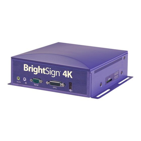
HARDWARE MANUAL
4K242, 4K1042, 4K1142
BrightSign, LLC. 16795 Lark Ave., Suite 200 Los Gatos, CA 95032 | 408-852-9263 | www.brightsign.biz
Table of
Contents
Previous
Page
Next
Page
1
2
3
4
5
Advertisement
Table of Contents
Need help?
Do you have a question about the 4K Series and is the answer not in the manual?
Ask a question
Questions and answers
Related Manuals for BrightSign 4K Series
Media Player BrightSign 4K242 Hardware Manual
(26 pages)
Media Player BrightSign 4K1042 Hardware Manual
(26 pages)
Media Player BrightSign 4K1142 Hardware Manual
(26 pages)
Media Player BrightSign HD120 Hardware Manual
Brightsign hd120, hd220, and hd1020 players (21 pages)
Media Player BrightSign XD230 Hardware Manual
Brightsign network media player hardware manual (23 pages)
Media Player BrightSign HD2000 User Manual
(112 pages)
Media Player BrightSign HD120 Quick Start Manual
Standalone digital sign and kiosk controller (28 pages)
Media Player BrightSign HD110 Quick Start Manual
(28 pages)
Media Player BrightSign HD222 Hardware Manual
(20 pages)
Media Player BrightSign HD110 Programming Manual
Digital signage media players - roku object reference (63 pages)
Media Player BrightSign XT243 Quick Start Manual
(10 pages)
Media Player BrightSign HD1022 Hardware Manual
(20 pages)
Media Player BrightSign XD1230 Technical Notes
Configuring for zeevee (4 pages)
This manual is also suitable for:
4k242
4k1042
4k1142
Table of Contents
Print
Rename the bookmark
Delete bookmark?
Delete from my manuals?
Login
Sign In
OR
Sign in with Facebook
Sign in with Google
Upload manual
Upload from disk
Upload from URL


Need help?
Do you have a question about the 4K Series and is the answer not in the manual?
Questions and answers