
Related Manuals for BrightSign HD120


Summary of Contents for BrightSign HD120
- Page 1 HARDWARE MANUAL BrightSign HD120, HD220, HD1020 BrightSign, LLC. 16795 Lark Ave., Suite 200 Los Gatos, CA 95032 | 408-852-9263 | www.brightsign.biz...
-
Page 2: Table Of Contents
TABLE OF CONTENTS OVERVIEW ..........................1 Block Diagram ................................... 2 Ports ....................................3 HD120 ....................................3 HD220 ....................................3 HD1020 ..................................... 4 Power Connector ................................5 DE9 RS-232 Connector ..............................5 DA15 Switch/LED Connector ............................. 6 Ethernet ..................................... 8 USB ....................................8 DE15 VGA Connector ................................ - Page 3 THEORY OF OPERATION ....................15 Power Supply .................................. 15 Reset ....................................15 BCM7208 CPU ................................15 Built-in Flash ..................................15 SDRAM .................................... 16 Serial Port ..................................16 Video Encoder and Filter ..............................16 Audio Outputs .................................. 16 On-Board LEDs ................................16 On-Board Switch................................
-
Page 4: Overview
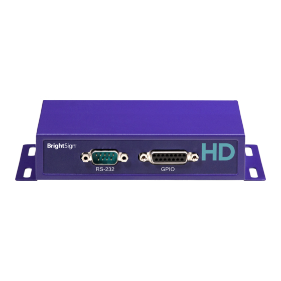
BrightSign HD120, HD220, HD1020 OVERVIEW The BrightSign HD120, HD220, and HD1020 players can be used to drive a variety of HDTV and computer monitors for digital sign and kiosk applications. In addition to driving a video display, these players have many different built-in interfaces that allow them to be controlled. -
Page 5: Block Diagram
All information provided in this reference manual applies to products under development. The characteristics and specifications of these products are subject to change without notice. BrightSign assumes no obligation regarding future manufacturing unless otherwise agreed to in writing. © BrightSign LLC, 2012... -
Page 6: Ports
All information provided in this reference manual applies to products under development. The characteristics and specifications of these products are subject to change without notice. BrightSign assumes no obligation regarding future manufacturing unless otherwise agreed to in writing. © BrightSign LLC, 2012... -
Page 7: Hd1020
All information provided in this reference manual applies to products under development. The characteristics and specifications of these products are subject to change without notice. BrightSign assumes no obligation regarding future manufacturing unless otherwise agreed to in writing. © BrightSign LLC, 2012... -
Page 8: Power Connector
DE9 RS-232 Connector The RS-232 connector is a male DE9. Like PCs, the BrightSign HD series of players are DTE devices. The input to the chip accepts a range between +30V and -30V, so it is compatible with standard +12V and -12V signaling. The output from the chip is rated at a typical +7V and -7V, which exceeds the voltage required by the RS-232 specification. -
Page 9: Da15 Switch/Led Connector
The connector can also supply 3.3 V at up to 500 mA to an external device. The 3.3 V output is polyfuse-protected and can source up to 500 mA. If one BrightSign player is driving the inputs on another BrightSign player, then you can drive at most three inputs from one output. The following calculations explain this limitation: Note: The GPIO outputs have 100 Ohm series resistors;... - Page 10 Here is the DA15 female as viewed from the front of the BrightSign HD120 and HD1020: A button/LED/IR board can be used to demonstrate the GPIO and IR functions on a BrightSign player. This board is built by a third-party manufacturer and can be purchased upon request.
-
Page 11: Ethernet
All information provided in this reference manual applies to products under development. The characteristics and specifications of these products are subject to change without notice. BrightSign assumes no obligation regarding future manufacturing unless otherwise agreed to in writing. © BrightSign LLC, 2012... -
Page 12: Triple Rca Component Hd Video Connector
3.5mm Audio Connector The HD120, HD220, and HD1020 each have one 3.5mm female audio connector, which transmits a stereo signal. The full scale voltage output of the audio is 2 V RMS, with no load. The minimum load resistance connected to the audio output should be 5K Ohms. -
Page 13: Hdmi Connector
All information provided in this reference manual applies to products under development. The characteristics and specifications of these products are subject to change without notice. BrightSign assumes no obligation regarding future manufacturing unless otherwise agreed to in writing. © BrightSign LLC, 2012... -
Page 14: Environmental And Power Usage
The HD120, HD220, and HD1020 players are designed to be used between 0°C and 40°C, at 90% maximum relative humidity, non-condensing. The power supply on the BrightSign HD series is 15 W and 5.0 V at 3 A. These players will use approximately 1 A of power when playing a 720p or 1080i MPEG2 HD source file. -
Page 15: Mechanical
All information provided in this reference manual applies to products under development. The characteristics and specifications of these products are subject to change without notice. BrightSign assumes no obligation regarding future manufacturing unless otherwise agreed to in writing. © BrightSign LLC, 2012... - Page 16 All information provided in this reference manual applies to products under development. The characteristics and specifications of these products are subject to change without notice. BrightSign assumes no obligation regarding future manufacturing unless otherwise agreed to in writing. © BrightSign LLC, 2012...
- Page 17 All information provided in this reference manual applies to products under development. The characteristics and specifications of these products are subject to change without notice. BrightSign assumes no obligation regarding future manufacturing unless otherwise agreed to in writing. © BrightSign LLC, 2012...
-
Page 18: Theory Of Operation
BCM7208 CPU The HD120, HD220, and HD1020 players utilize a BCM7208 Multimedia CPU. This CPU runs on 3.3 V, 2.5 V, and 1.2 V and runs from a 27 MHz oscillator. The CPU is reset by the RESET_L signal from the low voltage reset circuit going into the RESET_IN pin on the BCM7208. -
Page 19: Sdram
SDRAM The HD120, HD220, and HD1020 players each contain one DDR SDRAM device. When the BCM7208 boots, it will copy the code from the NAND flash device into the SDRAM and then execute the code from the SDRAM. The SDRAM runs at a clock rate of 666MHz, with a data rate of 1333MHz. -
Page 20: On-Board Switch
All information provided in this reference manual applies to products under development. The characteristics and specifications of these products are subject to change without notice. BrightSign assumes no obligation regarding future manufacturing unless otherwise agreed to in writing. © BrightSign LLC, 2012... -
Page 21: Sdhc/Sd Flash Slot
NAND Flash BrightSign players have a built-in NAND flash. All the code for the player is stored on the NAND flash. It may also be possible to store some content on the NAND flash, which is connected directly to the BCM7208.
Need help?
Do you have a question about the HD120 and is the answer not in the manual?
Questions and answers