
Related Manuals for Electrolux ComfortLift ESF8735ROX


Summary of Contents for Electrolux ComfortLift ESF8735ROX
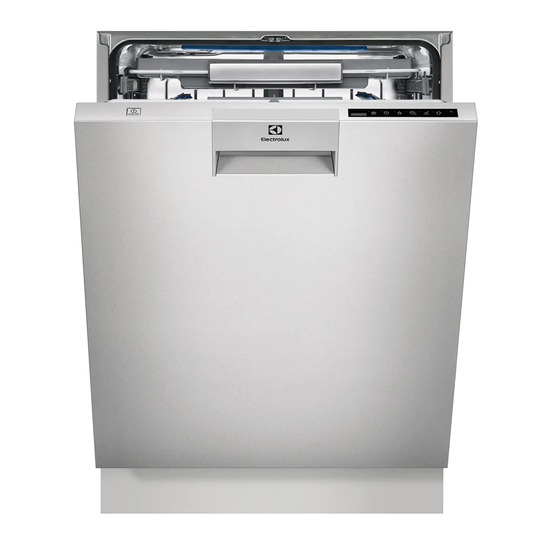
- Page 1 ELECTROLUX HOME PRODUCTS PTY LTD ABN 51 004 762 341 Issue: 2 Technical Publication Nº DWSI1012 Date: 11/17 SERVICE MANUAL DOMESTIC HOUSEHOLD ComfortLift DISHWASHERS Copyright 2017 ELECTROLUX HOME PRODUCTS PTY LTD Technical Services ...
-
Page 2: Table Of Contents
CONTENTS Purpose of this manual ......................... 3 Precautions ............................ 3 Technical details ........................... 4 3.1. Product overview ........................4 3.2. Structural Parts .......................... 5 3.3. Base ............................6 3.4. Bottom tray..........................7 3.5. Water circuit ..........................8 3.6. Hydraulic circuit ......................... 9 3.7. -
Page 3: Purpose Of This Manual
1. Purpose of this manual The purpose of this Service Manual is to provide Service Engineers with technical information regarding the new range of “Dorotea” dishwashers and to give a description of the service functionality. This Manual describes: • General characteristics •... -
Page 4: Technical Details
3. Technical details 3.1. Product overview Global hydraulics Thin inner door with Global dispenser Global door lock with auto door opening integrated PB100 / PB200 Main board Wash pump with integrated Sidekick connection possible also heater from the front of the appliance 4/60... -
Page 5: Structural Parts
3.2. Structural Parts The counterweight slides under the rear bar and is attached with 2 screws in the base. 1- Counterweights 2- Base 3- Bottom tray 4- Inner fire shield 5- GMB Box (Covered in 6- Metal cover Electronic System) 5/60... -
Page 6: Base
3.3. Base Rear side Inner side 1- Ribs to prevent that water 2- Area for swing in and attach sprays in to the circuit board the counter weights with if the hose is damaged on screws the outside just after coming 1- Holder for active drying 2- Cable exit and holders for out from dishwasher... -
Page 7: Bottom Tray
3.4. Bottom tray Details Assembly instructions 1- Screw bosses that is only 2- Snaps for assembling tray to 1- Insert bottom tray (without 2- Keeping bottom tray pushed planned to be backup if the base metal feet), the tabs on the inwards, rotate it into place snaps fails tray must match the slots in... -
Page 8: Water Circuit
3.5. Water circuit WATER OUTLET WATER INLET BLENDED FUNCTION SENSOR WASH PUMP PRESSURE + HEATER TURBIDITY SENSOR SUMP salt DRAIN PUMP REGENERATION VALVE AQUA CONTROL 8/60... -
Page 9: Hydraulic Circuit
3.6. Hydraulic circuit 1- Drain hose. 2- Wash pump with integrated heater 3- Hose pump-sump 4- Drain pump (included with sump) 5- Sump 6- Hose pump- FC/FD (included with pump) 7- Flow controller (FC) 8- Hose softener- or Flow distributor sump (FD) 9- Sensors... - Page 10 1- Softener-sump hose: 2- Overflow hoses: 1- Pressure sensor with radial 2- Pressure sensor snap: Corrugated pressed and The same parts for both sealing robust snap from bottom sealed using o-ring sides. Position provided by ribs in sump to limit compression.
-
Page 11: Sump Circ Motor And Heater
3.7. Sump Circ Motor and Heater Main Pump assembly: For both motors the heater is available as separate spare part Common interface with new volute Basement fixation is same Includes hose to flow controller Includes pump-sump hose Includes Omega heater Includes steel shield around 1- BLDC motor with Flow Control 2- Omega heater... - Page 12 Single phase asynchronous washing pump motor with FD Three phase washing pump BLDC motor with FC Connection-plan BLUE BROWN MAIN 1 WHITE 2 BROWN 230/240 V 50/60 Hz Class F Resistance: 1-2: 56 ohms/2-3: 56 ohms/3-1: 56 ohms 12/60...
- Page 13 Omega heater: Voltage EU 220-240 V, Power: 1800 W Voltage EU 220-240 V, Power: 2040 W 1- Electric connection of the 2- Ground connection heater 1- Heater Cover 13/60...
-
Page 14: Sump And Drain System
3.8. Sump and drain system Three-phase Synchronous BLDC motor Single-phase Synchronous motor 3- Cuff on drain hose: 4- Drain pump (Single-phase 1- Cuff on drain hose: 2- Drain pump (Three-phase Clamped to drain outlet. Synchronous motor ): Clamped to drain outlet. Synchronous BLDC motor): Positioned by rib in sump Fixed directly in sump built-... - Page 15 Drain pump - Three-phase Synchronous BLDC motor Drain pump - Single-phase Synchronous motor Voltage 230 V 50 Hz Power: 21 W resistance 93 ohms +/- 10% Max flow rate: 15 litre/min Voltage 230 V 50 Hz Power: 30 W resistance aprox 225 ohms Max flow rate: 15 litre/min 1- Cover 2- Housing...
-
Page 16: Flow Controller
3.9. Flow controller Details The flow controller is designed to control the water flow towards the top spray arm only, bottom spray arm only or towards both spray arms. 1- Micro switch 2- Synchronous motor 1- Water outlet to lower spray 2- Water outlet to upper spray 230V AC, 50/60Hz arms... -
Page 17: Pressure Sensor
3.10. Pressure sensor Details Frequency output (0-5V Signal), Range: 0-300mm Connection: 3 connectors RAST 2.5mm 1- Pressure sensor with radial 2- Pressure sensor snap: sealing robust snap from bottom ribs in sump to limit rotation half round rib to limit move upward Pressure mmWc/PA... -
Page 18: Turbidity Sensor (High Power Sensor)
3.11. Turbidity sensor (High power sensor) Control both the temperature and the turbidity of the washing water. Positioned externally on the sump in direct contact with the water. Fitted with an NTC sensor for control of the temperature. Fitted with an infra-red system for control of the turbidity of the water (i.e. -
Page 19: Automatic Cycle: Autosense
3.12. Automatic Cycle: AutoSense The AutoSense software – Washes the dishes and detaches the dirt continuously – In this way the turbidity sensor can detect the degree of dirtiness – And will define, if additional rinses are necessary. – The measurements will be done continuously during the cycle. -
Page 20: Global Dispenser
3.13. Global Dispenser Details The dispenser have the following main features: • Low voltage driving - 5VDC => Safety improvement • Multiple dosage => Performance/Quality improvement • Sliding lid => Performance/Quality improvement It’s present on dishwashers with “Thin inner door”. Assembly process as today. -
Page 21: Multi Dosage - Specification
3.14. Multi Dosage – Specification PERFORMANCE The dosage of the rinse-aid has to be independent of the filling status of the container, as long as the refill indication isn’t reached. After indicating the refill minimum for another 2 dosage cycles the nominal volume has to be guaranteed. ... - Page 22 During main wash phase – Detergent lid opening: Step Action Time Purpose Activation of coil 0.3 s Opening the detergent lid to release detergent During hot rinse phase – Rinse aid delivery: Step Action Time Purpose Dosage check - Check if rinse aid should be delivered If 0 ...
-
Page 23: Xtradry Option
3.15. XtraDry option The XtraDry option increases drying performance and impact the following: • Extension of the drying phase • Higher temperature in the rinse cycle • Increase adding of rinse aid PROGRAM DRYING PHASE TEMPERATURE HOT RINSE RINSE AID Intensive 70°C +30min +1°C (70°C) -
Page 24: Door Lock With Auto Door Opening - 2Nd Generation
3.17. Door Lock with Auto Door Opening – 2nd generation Diamond Latch Doorlock Opening and Closing feeling are The door lock is fixed on the upper front defined by the shape of the cross bar, springs are adjusted to 50/60N. Diamond Latch sitting in the door Hinges Doorlock with Auto Door... - Page 25 The door lock will have in the same part as the auto door opening. The door will open because of the new door hinges. The door lock, auto door opening and door hinges allow this new integrated system for better drying performance. 1 –...
- Page 26 The Diamond Latch is fixed on the door, and it’s possible to adjust the Diamond Latch's position. How to adjust the Diamond Latch position Loosen the right screw of the Diamond Lift up the Diamond Latch between 2 Fix the right screw again to lock the fingers.
- Page 27 Disassembly: The door lock is snapped and fixed with 2 screws on the upper front cross bar, to exchange it, the crossbar has to be taken. When replacing the Door lock or Door lock with Auto door opening do not Pull on the wire’s –...
- Page 28 Assembly: • Use manual screw driver to avoid overturning and damaging the screws • Make sure wires are not twisted or damaged • Regarding the Wax motor – polarization does not matter • Put the wires in the cable channel Put the new cover of the door lock •...
- Page 29 Auto door opening (ADO) – working description ADO 1st Generation (previous) When the machine is done with the washing cycle, the door will open: - The Wax motor in the auto door opening (ADO) is activated - Latest 2min later the door lock release the door. - The door falls through the weight of the door itself to 10cm opening, because the hinges are balanced for 10cm opening.
- Page 30 How to check the Auto door opening (ADO) Open the door Activate service mode Go to actuator position 10 Close door Wait 2 minutes for the door to open Check if the door opens 10cm between the upper front cross bar and inner door Door not closing Probably the Auto door opener is still active.
-
Page 31: Electronic Main Boards
3.18. Electronic Main Boards • The main board is placed on the rear side of the appliance in the basement area. • The electronic board is assembled in a fire protected area. • The metal cover works as fire protection and avoids mechanical damages on the main board. - Page 32 PB100 PB150 PB300 Features possible to support PB100 PB200 (Depending on mounting option) - High and Mid range covering all platforms. Existing HV main switch Supports both EU and NA via population Existing LV main switch Auto-off functionality options. Future logic main switch - BLDC wash and drain motors.
- Page 33 Electronic Box for Main Board PB100 / PB200 Electronic Box for Main Board PB300 Electronic Box for Main Board PB150 1- Probe-slots for testing PCB 2- Fastening hooks goes into One for each connector the base and locked by ribs in lower edge of the base 3- DAAS-connector position Open interface due to easy...
- Page 34 Metal cover for Main Board Inner fire shield The metal cover is a fire shield and protects the electronics from mechanical stress. 1- The yellow/green wire must 2- Hole for pin, holding cover be connected to the metal in place before screwing it to 1- Inner fire shield 2- Metal cover to be cover when the part is put...
- Page 35 Main board disassembly 1- Remove 4 screws from the 2- Remove the metal cover cover 3- Unlock the 2 hooks 4- Pull the main board box downwards 35/60...
-
Page 36: Components Check
3.19. Components check PB100 BLDC PB150 BLDC PB200 ASY PB300 ASY CORRECT PARTS LEAD LEAD LEAD LEAD REMARKS VALUE CONNECTIONS CONNECTIONS CONNECTIONS CONNECTIONS A5 ↔ L A5 ↔ L A5 ↔ L A5 ↔ L 0 Ω POWER CABLE A6 ↔ N A6 ↔... -
Page 37: Water Reuse N/A
3.20. Water Reuse N/A A water Reuse tank is placed on the right side of the dishwasher. The tank purpose is to save 3.5 lt of water from the cold and hot rinse in Energy Label & Intensive programs and use them in the Pre wash of next cycle. This allows reducing the water consumption. - Page 38 Three phase washing pump BLDC for water reuse N/A The only part that is visible is the nut inside the tub in the location of the internal light on the right side. 38/60...
-
Page 39: Comfort Rails
3.21. Comfort rails Basket disassembly The procedure is similar for both baskets, and is done with the baskets fully out. Detail of the snap to press and movement on step 2 1- Remove the screws 2- Press the snap and fixing the basket to the slide the basket while rails... - Page 40 Top rails disassembly 1- When rail is aligned 2- Press the snap and as shown on the slide the rail in picture, the snap to direction to the front press is located in of the dishwasher. hole marked on the This movement picture.
- Page 41 Intermediate rails disassembly 1- Press the four snaps and slide the rail in direction to the front of the dishwasher. This movement should be small enough just to release the rails from the tub It’s also possible to disassemble the rails by removing the side panels, and removing the plastic part fixed to the tub.
-
Page 42: Comfort Lift
3.22. Comfort lift A mechanical system that lifts the bottom basket. When lifted the basket will remain on that position by action of a locking device. 1- Main handle 2- Unlocking handle 3- Safety cover 4- Strut 42/60... - Page 43 Lift the basket Don’t pull the unlocking handle Pull the handle off the basket. Lower the basket Pull up the unlocking handle to lower the basket. 43/60...
- Page 44 Failure situations and actions to perform: (*) Information on how to do the component repair / replacement indicated on the action to perform is available after this failure situations table. Failure description Possible causes Action to perform Basket swings down too fast Dishwasher is not levelled and is leaning Level the dishwasher.
- Page 45 Failure situations and actions to perform (cont.): (*) Information on how to do the component repair / replacement indicated on the action to perform is available after this failure situations table. Failure description Cause Action to perform Basket stuck or difficult to move. Basket front stoppers bad positioned Put front stoppers on the correct position.
- Page 46 Basket disassembly With the basket on lower position To disassemble the basket, it is necessary to have it on the lower position, otherwise the lifting mechanism locks the basket and it is not possible to disassemble it. 1- Press the snap to remove 2- With the snap pressed, pull the plastic locking part the plastic lock.
- Page 47 4- Pull the basket as far out as possible without engaging the rotational lifting movement. Then on each side pull the snap 1 cm against middle of dishwasher and in the same time pull the basket out minimum 1 cm. 5- Slide the rails on both sides to the interior of the dishwasher while holding the basket 47/60...
- Page 48 Basket assembly With the lift mechanism on lower position To assemble the basket, it is necessary to it have on the lower position, otherwise the lifting mechanism collides with the basket and it is not possible to assemble it. 1- Insert the basket on the rails 2- Make sure the basket is 3- Assemble the plastic 4- Do this operation on left...
- Page 49 Safety cover 1- The safety cover snaps 2- Fix point 3- Movement to disassemble When assembling align the cover on the fix point and rotate the other side up to snap it (inverse movement from disassemble). On assembly and disassembly procedure, lower the lifting mechanism at least 5 cm.
- Page 50 Gas Strut replacement N/A. The easy movement of the ComfortLift mechanism is possible because of this gas strut. Any operation of disassembly or assembly of the gas strut must be done with the ComfortLift mechanism on lower position; the gas strut must be on the position shown on the picture above.
- Page 51 Lift mechanism replacement N/A 1- Remove the basket (Refer 2- Slide out the two guides to “Basket disassembly “ Keeping the syncro bar firm with one hand, unlock the right side pin. 3- Keep the syncro bar firm with one hand. 3.1 - Unlock the right side pin.
- Page 52 5- Drill both rivets from both side (4 rivets) with Ø10mm drill bit. Keeping the syncro bar firm with one hand, lift the system up. 4- Place protective foil onto inner door and tub to protect them from scratching or denting. 6- Remove the syncro bar 52/60...
- Page 53 7- Unscrew the 3 fixation screws from the faulty hinge module (left or right or both) 8- Remove the faulty hinge module (left or right or both) 9- Assemble the safety cover on the new hinge module to avoid finger trapping during operation ( refer to specific section “Safety cover”) Remove cork from the strut to avoid any risk to have it in the sump.
- Page 54 Position the new syncro bar like the picture (bending inside) Move the system in lower position (inside tub), and keeping the syncro bar firm with one hand 14.1 - Unlock the left side pin. 14.2 - Unlock the right side pin. Bend inside 14.3 - Push the syncrobar into the tub 14.1...
- Page 55 14.2 Keeping the syncro bar firm with one hand, Keeping the push the 14.3 syncro bar firm syncrobar into the with one hand, tub. unlock the right side pin. Reassemble the basket, ( refer to specific section “Basket assembly”) 55/60...
- Page 56 Tub bracket replacement N/A (tub bracket - plastic part connecting the lift mechanism to the tub) 1- With the lift mechanism on the lower 2- Unscrew the 3 interior position, it is necessary to remove the fixation screws dishwasher from the niche and/or remove the side panels to have access to the 3 metallic nuts that fix it to the tub on each side.
- Page 57 3- Place the new tub bracket and 4- To fix from the exterior of the screw the 3 interior screws tub start with the upper front with manual screwdriver, not nut. Use a manual tool not a automatic one (max force automatic one (max force torque 3,8Nm).
- Page 58 Self closing unit replacement 1- Remove the basket (Refer to 2- Identify Self closing unit in red “Basket disassembly “ rectangle 3- Use screw driver to unlock Self 4- Unsnap the Self closing unit closing unit . from basket. 5- Place the new one with reverse precedure. 58/60...
- Page 59 Roller cage replacement 1- Put the screwdriver inside the guide to push the plastic tooth to 2- Move the rail out to slide out the roller cage. unlock it. 59/60...
- Page 60 3- Assemble the new Roller cage sliding on the guide till the end of 4- Insert the rail inside the guide till the end. the guide (spec. The arrow on roller cage must be directed pointing outside the dishwaher) Arrow on plastic in this direction 5- Reassemble the rack.
Need help?
Do you have a question about the ComfortLift ESF8735ROX and is the answer not in the manual?
Questions and answers