Table of Contents
Advertisement
Advertisement
Table of Contents

Related Manuals for Carmanah M650H


Summary of Contents for Carmanah M650H
- Page 1 M650H USER MANUAL Technical Support: Email: customerservice@carmanah.com Toll Free: 1.877.722.8877 (US & Canada) Worldwide: 1.250.380.0052 Fax: 1.250.380.0062 Web: carmanah.com © 2014, Carmanah Technologies Corporation. June 2014. 61249_M650H_User_Manual_RevC...
-
Page 2: Warnings And Precautions
Battery Pack Health status reading is obtained when the Regulatory Information M650H has been in a dark location and in Off mode for at least 24 This Class [B] digital apparatus complies with hours. Canadian ICES-003. -
Page 3: Table Of Contents
Distributor Functions ..........48 Fog Mode .............20 Logging In ............48 Infrared Remote Programmer (Optional) ..... 20 Configuring the M650H ........49 Entering the Deployment Location ....... 50 Setting the User’s Device Access ......51 © 2014, Carmanah Technologies Corporation. June 2014. 61249_M650H_User_Manual_RevC... - Page 4 Entering the Passcode .........57 Changing the Flash Code ........58 Turning the M650H Off ........59 Setting the M650H to Ship Mode ......59 Restoring the M650H from Ship Mode ....60 Determining the Battery Pack's State of Health ... 60 Appendix C: Accessories ........61 M650H Accessories ..........61...
-
Page 5: Introduction
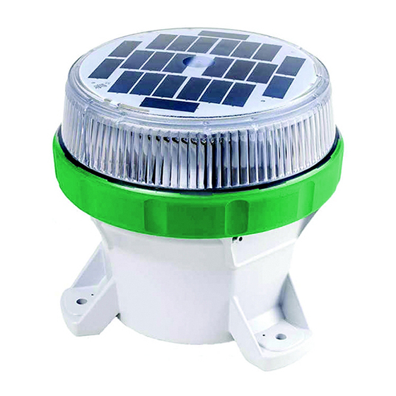
Introduction Common Features and Functionality The M650H: M650H Applications • Is a self-contained, high-performance, low- The M650H Solar Marine Lantern has the following maintenance and easy-to-install solar-powered marking applications: light source. • Aids to navigation • Is programmed for geographical location to •... - Page 6 • Is available in red, green, yellow, white and blue LED output colours. • Is designed in accordance with the European Union's guidelines for the Restriction of Hazardous Substances in electronic equipment (RoHS). © 2014, Carmanah Technologies Corporation. June 2014. 61249_M650H_User_Manual_RevC...
-
Page 7: M650H Parts Description
USB port battery connector removable bottom cover battery strap bottom cover locking battery strap tab tab and screw BOTTOM VIEW INTERNAL VIEW (BOTTOM COVER REMOVED) © 2014, Carmanah Technologies Corporation. June 2014. 61249_M650H_User_Manual_RevC... -
Page 8: Getting Started
The M650H User Manual of the mounting foot. The Bird Deterrent extends NOTE (this document) is separate from over the top of the M650H to prevent birds from the M650H and is available for landing on the M650H. download in PDF format from carmanah.com. -
Page 9: Bottom Cover Lock
In the On position, a “I” symbol is visible on Bottom Cover Lock the switch. You can lock or unlock the M650H Bottom Cover by tightening or loosening the locking screw from the tab on the Bottom Cover. Tightening the screw renders the Bottom Cover tamper-proof when it is installed against a flat surface using security fasteners. -
Page 10: Operation
M650H USER MANUAL Operation Installing the M650H The M650H has three mounting feet with holes for Choosing an Installation Location ¼” (M6) fasteners (fasteners are not included, and can be ordered as an optional kit). The three holes Full solar exposure is critical to the are 120°... -
Page 11: Configuring The M650H
M650H using the OBUI. NOTE 650 Device Manager software to configure your M650H. Using the 1. Turn the M650H upside down and place it on a 650 Device Manager software, soft cloth (to avoid scratching the housing). the Distributor can program a... -
Page 12: Status Report
4. Lift the cover out by pushing up on the protruding locking tab. You now have access to the OBUI When you are logged in to the M650H, you will see two buttons or the USB connector port (for using the additional parameters: 650 Device Manager software). -
Page 13: Editing Parameters
Edit will appear on the display. The display will then repeat the status report, finishing with Hold Set to Before you can edit any of the M650H’s parameters, Edit. The display will then turn off. you must enter a Passcode. The default Passcode is 753. -
Page 14: Editing The Flash Code
Flash Code, the display If you need to change the Flash Code (for example, indicates the new maximum when you have to move an M650H from one buoy to Effective Intensity, and allows it to another), use the following procedure:... -
Page 15: Editing The Automatic Light Control (Alc) Mode
Editing the Date effective intensity based on the new Flash Code and installation location The M650H has an internal clock which it uses for latitude and longitude. logging activity. The current date is written in non- volatile memory, so if the Battery Pack is unplugged... -
Page 16: Setting The Calendar Function
OBUI display. will end. 2. Enter the Passcode to log in to the M650H. 4. Press the set button briefly. The day starts to flash on the OBUI display. -
Page 17: Gps (Optional)
OBUI display. • Ship Mode • 24-Hours Shutdown 2. Enter the Passcode to log in to the M650H. • Low Battery Disconnect 3. After logging in, press the up or down buttons • Rotary switch turned off (Switched Models) until the word RSET appears on the display. -
Page 18: Installing The Bottom Cover
Ensure that the inside surfaces of the up with the locking screw. M650H that the o-rings will contact are also clean. 2. If the Bottom Cover was difficult to remove, apply a very thin coating of silicone o-ring lubricant to the two o-rings on the Bottom Cover before 6. -
Page 19: 650 Device Manager Software
650 Device Manager Software On/Off Switch Before deploying and installing the M650H, you can You can place the M650H in one of three modes connect it to a computer (using a USB cable) and use using the On/Off switch: the 650 Device Manager software to: Off Mode •... -
Page 20: Fog Mode
M650H USER MANUAL While in Standard On Mode, the M650H continues to Mode, the M650H turns on and remains on for the charge its batteries when exposed to light. rest of that day. To place the M650H in Standard On Mode, switch Infrared Remote Programmer the On/Off switch to the On position. -
Page 21: Battery Pack
4.2V). Low: the Battery Pack is so low (<3.9V) that the low Charging the Battery Pack battery cutoff is active and the M650H will not light up when dusk arrives. Solar Charging Bad: the Battery Pack is damaged and should be recycled and replaced with a new one. -
Page 22: Charging With An Artificial Light Source
1. Remove the Bottom Cover. • Do not place the light source too close to the M650H solar panel, as very high temperatures can damage 2. Unplug the Battery Pack connector by pressing the lantern. -
Page 23: Storage Procedures
Battery Pack state of health. Replacing the Battery Pack At the end of the M650H Battery Pack’s life, you can remove it and replace it. Always recycle used Battery Packs appropriately. To remove the Battery Pack:... - Page 24 M650H receptacle. Continue to hold the Set button until Zero is displayed briefly. This resets the M650H’s Battery Pack health monitor. Do not hold the Set button while reconnecting a used battery. © 2014, Carmanah Technologies Corporation. June 2014. 61249_M650H_User_Manual_RevC...
-
Page 25: Maintenance
Maintenance After installation, the M650H requires no day-to-day maintenance. On occasion, you may want to inspect the M650H to ensure the solar panel has not been fouled by birds or covered in debris. You can clean an M650H with water and a mild detergent. -
Page 26: Recycling
When the M650H reports the Battery Pack's Health as "bad", the Battery Pack should be removed from the M650H and replaced with a new Battery Pack. Consult carmanah.com or your Carmanah dsitributor. Bring the used Battery Pack to a lead-acid battery collection, or appropriate recycling facility. -
Page 27: Shipping
M650H in Ship Mode using the 650 Device Manager software. After the M650H enters Ship Mode, place it into the box in which it is being stored or shipped, and close the lid to ensure it stays in darkness. The main LED remains off until the M650H is removed from the box and senses a day-to-night transition. -
Page 28: Appendix A: 650 Device Manager Software
Distributors also have access to a suite of advanced features. System Requirements The M650H requires an updated (version 2) copy of the 650 Device Manager software. You can download version 2 from the Carmanah Partner Portal (login required). To run the 650DM software, your computer must meet the following requirements: 2. -
Page 29: Removing The Bottom Cover
3. Secure the lantern so it won’t move, and then firmly twist the Bottom Cover counter-clockwise until it stops. Congratulations, you have successfully completed your 650 Device Manager installation. © 2014, Carmanah Technologies Corporation. June 2014. 61249_M650H_User_Manual_RevC... -
Page 30: Logging In
Device Manager software, connect the larger end new lantern. to an available USB connector in your computer. Connect the other smaller end to the USB connector inside the M650H. USB cable © 2014, Carmanah Technologies Corporation. June 2014. 61249_M650H_User_Manual_RevC... - Page 31 USB cable, then after a short pause, the 650DM software connects to the lantern, and a coloured picture of the M650H on the main screen replaces the darkened picture. The picture that appears matches the LED colour of the M650H.
- Page 32 As a User, you can access the following pages: Status: (the default page when you log in): This page contains basic status information about the M650H that is currently plugged into the computer. Configuration: This page displays the attached lantern’s current configuration, and allows you to change various settings (for example, Flash Code and Effective Intensity).
-
Page 33: Checking The Lantern's Status
Code Table Version Flash Code Table Version: the version of the Flash Code Table that is currently loaded on the lantern. The Firmware and Flash Code Table Version area contains the following information: © 2014, Carmanah Technologies Corporation. June 2014. 61249_M650H_User_Manual_RevC... -
Page 34: Configuration Page
650DM setpoint(s) in the Setting Columns and then sending the setting(s) to the lantern using the Send Settings to Device button. A User cannot edit the Geography NOTE or the Set Device Access areas. © 2014, Carmanah Technologies Corporation. June 2014. 61249_M650H_User_Manual_RevC... - Page 35 Peak Intensity value, unlike the Effective Intensity value, does not take into account the programmed Flash Code: it is the instantaneous intensity of the lantern during the “on” portion of the Flash Code. © 2014, Carmanah Technologies Corporation. June 2014. 61249_M650H_User_Manual_RevC...
- Page 36 Restore Defaults: This restores the settings that were last programmed at the Distributor or Manufacturing Access Level. If the lantern’s settings have only been changed at the User Access Level, the settings return to what they were when you first received the lantern. © 2014, Carmanah Technologies Corporation. June 2014. 61249_M650H_User_Manual_RevC...
-
Page 37: Sw Admin Page
The Com Port field displays the current communications port through which the lantern is connected to the 650DM. Connection Tab: 650DM Version This field displays the version of the 650DM currently installed on the computer. © 2014, Carmanah Technologies Corporation. June 2014. 61249_M650H_User_Manual_RevC... - Page 38 If you are logged in as a User, you will only see the Access Level NOTE “User”. If you are signed in as a Distributor, you will see both Distributor and User. © 2014, Carmanah Technologies Corporation. June 2014. 61249_M650H_User_Manual_RevC...
-
Page 39: Initial Configuration
M650H USER MANUAL Initial Configuration After receiving your lantern from a Carmanah Distributor, most of the lantern’s settings should already be configured. If you want to further customize these settings, follow the associated procedure. SETTING DEFINITION PROCEDURE Flash Code The Flash Code controls the flash pattern the lantern Either type in the correct Flash Code, or emits during operation. - Page 40 ~24h, at which time it will automatically enter Ship Mode. To conserve battery power, however, it’s preferable to put the lantern into Ship Mode prior to dark storage. © 2014, Carmanah Technologies Corporation. June 2014. 61249_M650H_User_Manual_RevC...
- Page 41 Restore Defaults to at the User Access Level, the settings will return to populate the Setting columns’ values what they were when you first received the lantern. with those originally programmed on the lantern. © 2014, Carmanah Technologies Corporation. June 2014. 61249_M650H_User_Manual_RevC...
-
Page 42: User Tasks
4. Click Configuration on the Bottom Bar. The Configuration screen appears. 5. Click Restore Defaults (on the right side of the screen). The lantern’s current settings are replaced with the settings last programmed by your Distributor or Carmanah Manufacturing. © 2014, Carmanah Technologies Corporation. June 2014. 61249_M650H_User_Manual_RevC... - Page 43 Effective Intensity Longitude and Atmospheric Transmissivity; set by Limit value increases. If the change requires your Distributor or Carmanah Manufacturing). more power from the lantern, then the Effective Intensity Limit value decreases. © 2014, Carmanah Technologies Corporation. June 2014. 61249_M650H_User_Manual_RevC...
-
Page 44: Entering/Exiting Ship Mode
5. Click Set Ship Mode On (on the right side of the screen). To confirm that the lantern is in Ship Mode, Ship Mode: On appears in the middle of the top bar © 2014, Carmanah Technologies Corporation. June 2014. 61249_M650H_User_Manual_RevC... -
Page 45: Setting The Time
Transition value is sent to the lantern. The values for Autonomy and the Effective Intensity Limit, in the Device column of the Derived Values area, change to reflect the effect of the new D2N Transition Level. © 2014, Carmanah Technologies Corporation. June 2014. 61249_M650H_User_Manual_RevC... -
Page 46: Setting The Night To Day Transition Level
Transition value is sent to the lantern. The values for Autonomy and the Effective Intensity Limit, in the Device column of the Derived Values area, change to reflect the effect of the new N2D Transition Level. © 2014, Carmanah Technologies Corporation. June 2014. 61249_M650H_User_Manual_RevC... -
Page 47: Changing The 650 Device Manager Password
This is the length of the shortest day of the year at 6. In the Confirm New Password field, re-type your the programmed latitude. new password. 7. Click Set Password. Your new password is now active. © 2014, Carmanah Technologies Corporation. June 2014. 61249_M650H_User_Manual_RevC... -
Page 48: Distributor Functions
After logging in as a Distributor, you will have access to the Maintenance page. Also, other areas of the Configuration page become editable. The Maintenance Page is available to a Distributor, but not a User. © 2014, Carmanah Technologies Corporation. June 2014. 61249_M650H_User_Manual_RevC... -
Page 49: Configuring The M650H
User. The Distributor Passcode field also becomes editable. Configuring the M650H The Distributor uses the same procedures as a User to configure an M650H lantern. Refer to User section for details on how to configure the lantern’s basic settings. -
Page 50: Entering The Deployment Location
AT is a measure of how well light NOTE transmits through the atmosphere. The AT can be set to 0.85, 0.80, or 0.74. If it is unclear which value to use, use the default value of 0.74.. © 2014, Carmanah Technologies Corporation. June 2014. 61249_M650H_User_Manual_RevC... -
Page 51: Setting The User's Device Access
Open the desired Configuration File by clicking Get Settings from File… (and proceed to the following step) 6. Browse to and Open the desired Configuration File. The settings from the Configuration File are entered into the Setting columns. © 2014, Carmanah Technologies Corporation. June 2014. 61249_M650H_User_Manual_RevC... -
Page 52: Creating A Configuration File
The order in which you do this is important; if you open the Configuration File and then connect to a lantern, the lantern’s values overwrite the settings in © 2014, Carmanah Technologies Corporation. June 2014. 61249_M650H_User_Manual_RevC... -
Page 53: Retrieving A Lantern's Configuration
File…. The Save As dialog box appears. lanterns as required. 6. Navigate to and save the file to an appropriate If an M650H is already connected to location. The file is saved in .DCF format. You can NOTE the 650DM, and you want to retrieve... -
Page 54: Changing Passcodes
Passcode Protected means that a User must enter Occasionally it may be useful to be able to update a Passcode on the OBUI before they can edit any new firmware to an M650H lantern. These files, settings. when necessary, will be supplied by Carmanah Technologies. -
Page 55: Updating The Flash Code Table
M650H USER MANUAL Updating the Flash Code Table Occasionally it may be useful to load a specific flash code table onto an M650H lantern. These files, when necessary, will be supplied by Carmanah Technologies. To update the Flash Code Table on a lantern: Do not disconnect the lantern while the 1. -
Page 56: Retrieving A Datalog
M650H USER MANUAL Retrieving a Datalog If you are experiencing technical difficulties with your lantern, Carmanah’s Helpdesk may ask you to send them a Datalog from the lantern that they can use for diagnostic purposes. To obtain a Datalog from a lantern: 8. -
Page 57: Appendix B: Using The Infrared Remote Programmer
(IR Remote) allows you to access a subset of the M650H functions. This is useful if the lantern is bolted 1. Point the IR Remote at the side of the M650H. down, preventing access to the On-Board User Interface (OBUI) or the USB connector. -
Page 58: Changing The Flash Code
To change the existing Flash Code: 1. After entering the Passcode, point the IR Remote at the side of the M650H lens and then press the Start button on the IR Remote. © 2014, Carmanah Technologies Corporation. June 2014. 61249_M650H_User_Manual_RevC... -
Page 59: Turning The M650H Off
Setting the M650H to Ship Mode To turn the M650H off using the IR Remote, you must If you are storing an M650H, or have to return it to set the Flash Code to "000". To do this: your distributor for maintenance or repair, it is best to put the M650H into Ship Mode or Off mode. -
Page 60: Restoring The M650H From Ship Mode
1. After entering the Passcode, point the IR Remote 1. After entering the Passcode, point the IR Remote at the side of the M650H lens and then press the at the side of the M650H lens and then press the IR Remote Start button. -
Page 61: Appendix C: Accessories
M650H USER MANUAL Appendix C: Accessories M650H Security Bolt Kit (Excludes Drivers) Part# 56578 The M650H Security Bolt Kit without drivers is ideal M650H Accessories for multiple unit installations that only require a single driver. Additional drivers can be purchased as Infrared Remote Programmer required. -
Page 62: Appendix D: Specifications
ESD: Tested to EN 61000-6-2:2001, +/-8 to +/-25 kV Solar Panel Blocking Diode Function: Yes Discharge Chemical Resistance: Tested to MIL-STD-810G, Method 504, Procedure II Flash Synchronization (Optional) GPS: Internal GPS Receiver with rapid signal lock © 2014, Carmanah Technologies Corporation. June 2014. 61249_M650H_User_Manual_RevC... -
Page 63: Standards And Testing (Continued)
-12GHz, 200V/m Battery Life: Tested equivalent to IEC 61427 5.11" (130 mm) 2.56" 2.56" (65 mm) (65 mm) 6.96" 1.48" (177 mm) (37.5 mm) 4.43" Centre (112.5 mm) of post 2.95" (75 mm) © 2014, Carmanah Technologies Corporation. June 2014. 61249_M650H_User_Manual_RevC... -
Page 64: Photometric Plots
M650H USER MANUAL Photometric Plots White Yellow Green Blue Peak IALA intensity dependent on NOTE location. Plot based on equatorial location of 12-hour night duration and 21% duty cycle flash code. © 2014, Carmanah Technologies Corporation. June 2014. 61249_M650H_User_Manual_RevC... -
Page 65: Appendix E: Flash Codes
Fl(2) 7s Fl(2) 8s Fl(2) 8s Fl(2+1) 10s Fl(2+1) 12s Fl(2+1) 12s Fl(2+1) 15s Fl(2+1) 6s Fl(3) 12S Fl(3) 10s Fl(3) 10s Fl(3) 12s Fl(3) 15s 10.7 Fl(3) 15s 10.5 Fl(3) 20s 12.5 © 2014, Carmanah Technologies Corporation. June 2014. 61249_M650H_User_Manual_RevC... - Page 66 Fl 10s Fl 10s Fl 10s Fl 12s 10.8 Fl 15s Fl 2.5s Fl 2.5s Fl 2.8s Fl 2s Fl 2s Fl 2s Fl 2s Fl 2s Fl 2s Fl 3s Fl 3s © 2014, Carmanah Technologies Corporation. June 2014. 61249_M650H_User_Manual_RevC...
- Page 67 Fl 6s Fl 6s Fl 7.5s ISO 10S ISO 2S ISO 4S ISO 5S ISO 6S ISO 8S ISO 3S LFL 10S LFL 10S LFL 10S LFL 12S LFL 15S LFL 5S © 2014, Carmanah Technologies Corporation. June 2014. 61249_M650H_User_Manual_RevC...
- Page 68 15S**** MO(U) 0.45 0.45 0.45 0.45 1.35 11.85 15S* MO(U) 0.55 0.35 0.55 0.35 1.45 11.75 15S** MO(U) 11.7 15S*** MO(U) 10S OC 10S OC 10S OC 15S OC 3S OC 3S © 2014, Carmanah Technologies Corporation. June 2014. 61249_M650H_User_Manual_RevC...
- Page 69 Q(3) 10S Q(3) 10S 0.35 0.65 0.35 0.65 0.35 7.65 Q(3) 10S Q(4) 10S Q(4) 12S Q(4) 15S 0.35 0.35 0.35 0.35 11.5 Q(4) 20S 16.5 Q(4) 6S Q(5) 10S Q(5) 20S 15.7 © 2014, Carmanah Technologies Corporation. June 2014. 61249_M650H_User_Manual_RevC...
- Page 70 0.35 0.15 0.35 0.15 0.35 0.15 0.35 0.15 0.35 0.15 0.35 0.15 0.35 0.15 5.85 VQ(9) 10S VQ(9) 10S Q(2) 7S Fl(2) 5s Fl(2) 10s Fl(5) 20s 13.5 Fl(2) 10s Fl 4s © 2014, Carmanah Technologies Corporation. June 2014. 61249_M650H_User_Manual_RevC...
- Page 71 Mo (0) 15s Q 1S 0.25 0.75 Q (3) 4.6s Fl 7.5s Fl (4) 11s FL (3) 21s 13.5 FL (3) 6s FL(3)10s FL(9)15s OC(2)6s OC(3)8s OC(4)10s FL(2)6s FL(1)8s FL(3)15s 10.7 FL(2)5s FL(2)4s © 2014, Carmanah Technologies Corporation. June 2014. 61249_M650H_User_Manual_RevC...
- Page 72 OC (3) 12S OC(4) 12S FL(3) 12S FL(4) 15S FL(5) 20S MO(A) FL(5) 20S 11.5 SADO FL(4) 15S FL(5) 20S Q(6)+LFL Q(9) 15S VQ(6)+LFL CST1 3.273 1.091 1.091 1.091 3.273 1.091 1.091 30 CST2 © 2014, Carmanah Technologies Corporation. June 2014. 61249_M650H_User_Manual_RevC...
- Page 73 CST14 CST15 CST16 CST17 CST18 10.5 CST19 CST20 CST21 Fl 3.5s Fl 3.6s Fl 5.5s Fl(3) 15s GpD(5) 14s GpD(5) 15s ISO 2.5S 1.25 1.25 Fl(3) 10s SYS: -297 future use ENDCODE © 2014, Carmanah Technologies Corporation. June 2014. 61249_M650H_User_Manual_RevC...
-
Page 74: Appendix F: Calculation Of Nominal Range And Effective Intensity
Visibility is a function of atmospheric transmissivity. Typically, transmissivity (T) = 0.74 and V = 18520 m (10 NM). At equatorial latitudes and clear skies, T = 0.85 and V = 34262 m (18.5 NM). © 2014, Carmanah Technologies Corporation. June 2014. 61249_M650H_User_Manual_RevC... - Page 75 = effective intensity (cd) = peak intensity (cd) C = visual time constant (s) F = flash duration (s) The visual time constant is 0.2 s for a lantern at night- time. © 2014, Carmanah Technologies Corporation. June 2014. 61249_M650H_User_Manual_RevC...
-
Page 76: Warranty
Customer Service Before contacting Carmanah’s Customer Service department, please have the serial number of your M650H available, a brief description of the problem, as well as all details of installation, storage, and recharging efforts. To contact Carmanah’s Customer Service... - Page 77 M650H USER MANUAL This page is intentionally blank. © 2014, Carmanah Technologies Corporation. June 2014. 61249_M650H_User_Manual_RevC...
- Page 78 © 2014 Carmanah Technologies Corporation carmanah.com Technical Support: Email: customerservice@carmanah.com Toll Free: 1.877.722.8877 (US & Canada) Worldwide: 1.250.380.0052 Fax: 1.250.380.0062 Web: carmanah.com © 2014, Carmanah Technologies Corporation. June 2014. 61249_M650H_User_Manual_RevC...
Need help?
Do you have a question about the M650H and is the answer not in the manual?
Questions and answers