
Related Manuals for BEKA BA364G


Summary of Contents for BEKA BA364G
- Page 1 BA364G and BA364E Two Input Intrinsically safe Counter Issue 5 Issue: 5 July 2019...
-
Page 2: Table Of Contents
Output pulse width: durAtion Installation Location Configuration example Installation procedure Units of measurement and tag marking on scale card. The BA364G and BA364E are CE marked to show compliance with the European Explosive Atmospheres Directive 2014/34/EU and the European EMC Directive 2014/30/EU... - Page 3 Maintenance Appendix 1 ATEX Dust certification 9.1 Fault finding during commissioning 9.2 Fault finding after commissioning Appendix 2 IECEx certification 9.3 Servicing 9.4 Routine maintenance Appendix 3 ETL & cETL certification gas 9.5 Guarantee and dust certification. 9.6 Customer comments Appendix 4 BA364E Two input Counter Accessories...
-
Page 4: Description
IECEx dust certification. Input A Input b Input A direction controlled by Input b For applications in the USA and Canada the BA364G and BA364E Counters have ETL & cETL certification Quadrature input which is described in Appendix 3. -
Page 5: Initialisation
2.1 Initialisation Each time power is applied to a BA364G Counter Note: When optional alarms are fitted, the BA364G initialisation is performed. After a short delay the Counter may be configured to provide direct access following display sequence occurs: to the alarm setpoints from the display mode when the ( and * buttons are operated simultaneously. -
Page 6: Intrinsic Safety Certification
Dust, IECEx and other approvals are each described contrast will be reduced. in separate appendixes to this manual. This allows the BA364G Counter to be installed in all gas Zones and to be used with most common 3.1 ATEX gas certification... -
Page 7: Pulse Input Terminals
BA364G for input A and between terminals 7 & 8 for parameters. input b, connects an internal 7V, 6mA supply to the respective input. Energising is not required when a BA364G input is connected to a voltage pulse 3.5.2 Sensors that require energising... -
Page 8: Remote Reset Terminals
3.6 Remote reset terminals 3.7 Certification label information The BA364G Counter may be reset to zero by The certification information label is fitted in a recess connecting the reset terminals RS1 and RS2 on the top outer surface of the instrument enclosure. -
Page 9: System Design For Hazardous Areas
BA364G Counter. Terminals 2, 6, 10 and RS2 of the BA364G Counter are internally connected together. If any of these terminals are earthed, as shown in Figs 2 & 3, the other terminals should only be connected to the same earth, i.e. -
Page 10: Pulse Input
4.1.2 Pulse input 4.1.5 Open collector input As shown in Fig 2 the BA364G can count pulses Most certified open collector sensors located in the from a wide variety of sensors in the hazardous same hazardous area as the BA364G Counter may area, or from the safe area as shown in Fig 3. -
Page 11: Remote Reset
500V rms insulation test to earth. No the correct function may be used. Zener barrier is required. A BA364G may also be remotely reset from the safe area. Any switch may be used but a Zener barrier is required to transfer the contact closure into the hazardous area which may be combined with the supply barrier so that only one package is required. -
Page 12: Pulse Input
4.2.2 Pulse input As shown in Fig 4 the BA364G can count pulses from a wide variety of sensors in the hazardous area, or from the safe area as shown in Fig 5. No galvanic isolator is required in series with the... -
Page 13: Magnetic Pick-Off Input
Two voltage pulse input ranges are selectable in the configuration menu, VoLt5 L and VoLt5 H. When configured for either of the voltage pulse ranges, the pulse input terminals 5 & 6 or 9 & 10 of the BA364G Counter comply with the requirements of simple apparatus. -
Page 14: Installation
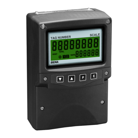
INSTALLATION Location The BA364G Counter is housed in robust IP66 glass reinforced polyester (GRP) enclosure incorporating an armoured glass window and stainless steel fittings making it suitable for exterior mounting in most industrial on-shore and off-shore installations. The Counter should be positioned where the display is not in continuous direct sunlight. -
Page 15: Emc
The BA364G complies with the requirements of the European EMC Directive 2014/30/EU. For specified immunity all wiring should be in screened twisted pairs, with the screens earthed at one point in the safe area. Units of measurement and tag marking on scale card. -
Page 16: Calibration Structure
6.1 Calibration structure Fig 9 shows the calibration structure of the BA364G Counter. The two pulse inputs are processed by the count function to produce a single output having the selected arithmetic function, such as the sum of pulse input A and pulse input b. -
Page 17: Summary Of Configuration Functions
LiGHt If after accessing the configuration menu the interval See section 6.6 between operating any front panel push button exceeds one minute, the BA364G will automatically return to the display mode and any configuration Contains sub-menu with two inPut-b changes will not be stored in permanent memory. - Page 18 Display Summary of function Display Summary of function Lower display dEbounCE [for Input-b] di5P-2 Defines level of input debounce Turns the lower display, which applied to the pulse input b to normally shows rate, on or oFF. prevent false counting: See section 6.15 dEFAuLt HEAVY...
-
Page 19: R5Et Def
See section 6.27 See section 6.21 Reset to factory defaults r5Et dEF Reset value Returns the BA364G Counter to the CLr VAL Defines a preset number to which factory defaults shown in section 6.0 the total display will be set when the... - Page 22 ONLY FOR GUIDANCE contacts or open collector sensors, terminals 3 Max counting frequency debounce & 4 of the BA364G should be linked together. level Type of input 3. To count correctly, the input pulse must fall Contact...
- Page 23 CoiL included in the configuration menu when the Proximity detector 2.1mA Pr . dEt BA364G Counter has a quadrature input A rEL b. Switch contact 1000Ω ContACt In quadrature mode the instrument will count up when the rising edge of input-b leads the rising edge of input-A.
- Page 24 & or * BA364G is configured to count up on a rising edge. button followed by the ) button to enter the selection and return to the configuration menu.
- Page 25 This function turns the lower display on or off. When 5CALE . t is a dividing factor adjustable between turned off, the BA364G will only have one eight digit 0.0001 and 99999 that enables the total to be display which may be configured in the di5P-1 displayed in engineering units.
- Page 26 6.19 Timebase: t-bA5E The timebase multiplies the rate display by 1, 60 or 3,600 depending upon whether the BA364G Counter During commissioning it is recommend that initially is required to display rate per second, per minute or the second digit is set to 0 (off) and the first digit is per hour.
- Page 27 This allows the BA364G to be used as a grand total display to zero from the display mode by pre-set down counter.
-
Page 28: Display Overflow
If this range is exceeded configuration menu and press ( which will cause the display will be as shown below with all of the the BA364G Counter to display 0000 with one digit decimal points flashing: flashing. The flashing digit may be adjusted using the &... -
Page 29: Pulse Output
This allows 7.2 System design pulse output terminals P1 and P2 to be directly The BA364G Counter pulse output is a passive connected to any intrinsically safe circuit protected circuit i.e. not powered, but it is totally isolated from by a certified Zener barrier or galvanic isolator all other Counter circuits. -
Page 30: Configuration
This sub-menu allows the source of the output pulse to be selected. For re-transmission applications the supply to the BA364G Counter is disconnected or output pulse may be a synchronous duplicate of the turned off, any stored pulses will not be retained. -
Page 31: Source Of Output Pulse: 5Ource
7.6 Source of output pulse: 5ourCE 7.8 Output pulse width: durAtion The output pulse may be derived from: When the output pulse is derived from the total display, the pulse width is defined by this function. One of 11 pulse widths in milliseconds may be Output is duplicate of input A dirECt A selected:... -
Page 32: Configuration Example
8. CONFIGURATION EXAMPLE Step 3 Select input count mode A BA364G Counter is required to display the position proximity detectors and speed, including direction, of a cable which is positioned so their outputs are electrically sensed by two proximity detectors mounted on a 90°... - Page 33 If input A occurs before prompt in the configuration menu by input b, a positive display will result when pressing ). the BA364G is configured to count up. Select uP or dn from the main menu and Step 9 Set the display timebase press ( to reveal the existing setting.
- Page 34 ) to return to the configuration menu. Step 14 Return to the display mode Following completion of configuration, return the BA364G to the display mode by pressing ). The instrument will display dAtA followed by 5AVE while the configuration changes are stored in permanent memory.
-
Page 35: Fault Finding During Commissioning
28V on terminals Note: Terminals 2, 1 & 2 with If a BA364G Counter fails after it has been 6, 10 & RS2 are terminal 1 functioning correctly, the following table may help to interconnected positive. -
Page 36: Accessories
The BA364G can also be supplied with a blank or custom laser engraved stainless steel legend plate - The BA364G internal counters are up-dated and see Fig 7. -
Page 37: Summary Of Configuration Functions
10.3.3 Summary of configuration functions remains non-alarm condition When a BA364G Counter is supplied with alarms the following acceptance of an alarm. configuration menu is extended as shown in Fig 16. See section 10.3.11 The alarm functions appear after LoC clr, each... -
Page 38: Alarm Enable: Enbl
10.3.4 Alarm enable: EnbL 10.3.5 Type of alarm: tYPE This function allows the alarm to be enabled or Alarm 1 and Alarm 2 are totally independent, both disabled without altering alarm may be rate or total alarms, or one may be parameters. -
Page 39: Setpoint Adjustment: 5P1X & 5P2X
H5tr prompt in the alarm sub-menu. All the setpoints are adjusted in the same way, for e.g. A BA364G Counter configured to display a rate example, to adjust the setpoint of Alarm 1 which has of 0 to 5000, with a high alarm set at 4000 and been configured to operate on the rate display. -
Page 40: Flash Display When Alarm Occurs: Fl5H
FL5H In addition to the two alarm annunciators on the left Access to the two alarm setpoints from the BA364G hand side of the BA364G Counter display which Counter’s display mode is obtained by operating the show the status of both alarms, this function... -
Page 41: 4/20Ma Output
To adjust an alarm setpoint select 5P1x or 5P2x and 10.4 4/20mA output press ( which will reveal the current setting. The The BA364G Counter can be supplied with an optional factory fitted galvanically isolated 4/20mA flashing digit of the setpoint may be adjusted using output which may be configured to represent the rate the &... -
Page 42: Configuration And Calibration
10.4.6 Select rate or total source: 4-20tYPE Fig 18 Application of 4/20mA output The 4/20mA output current can represent the BA364G Counter’s rate or total display and this must be defined before any other 4/20mA current output 10.4.3 Configuration and calibration functions are configured. - Page 43 10.4.8 Display which corresponds to 20mA output: 20. 0 00 The BA364G Counter display which corresponds to 20.000mA output current is defined by this function. Using the & or * push button select 20 . 000 in the 4/20mA output sub-menu and press (. to reveal the existing rate or total display with one digit flashing.
- Page 44 Before replacing the BA364G Couinter also has ATEX dust certification. instrument assembly the sealing gasket should be inspected to ensure that it is undamaged and free from foreign bodies.
- Page 45 For additional information about the IECEx certification scheme and to view the BEKA associate certificates, please visit www.iecex.com A2.1 IECEx Certificate of Conformity The BA364G Counter and the optional accessories have been issued with an IECEx Certificate of Conformity number IECEx ITS 16.0004X which...
- Page 46 A3.0 cETL Mark For installations in the USA and Canada, the Installations must comply with BEKA associates BA364G Counter has ETL and cETL intrinsic safety Control Drawing CI330-53, which is attached to this nonincendive approval, Control Number appendix, and with the local codes of practice.
- Page 59 The safety parameters and certification numbers or 1 row of 11 alphanumeric characters 7mm high specified in this manual for the BA364G Counter also apply to the BA364E Counter. Therefore all of the or 2 rows of 18 alphanumeric characters 5mm systems described for the BA364G in the main high.
- Page 60 A4.5 Installation Procedure Fig A4.1 illustrates the instrument installation procedure. a. Remove the instrument terminal cover by unscrewing the two captive 'A' screws. b. Mount the instrument on a flat surface and secure with screws or bolts through the two 'B' holes.
Need help?
Do you have a question about the BA364G and is the answer not in the manual?
Questions and answers