Table of Contents
Advertisement
Quick Links
Advertisement
Table of Contents

Related Manuals for BEKA BA568E


Summary of Contents for BEKA BA568E
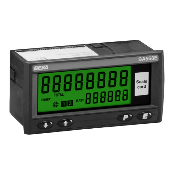
- Page 1 BA568E Two Input General purpose Counter Issue 5 Issue: July 2019...
-
Page 2: Table Of Contents
Select rate or total source 5.27 Security code 9.5.6 Define display for 4mA output 5.28 Reset configuration to factory defaults 9.5.7 Define display for 20mA output 5.29 Display overflow The BA568E is CE marked to show compliance with the European EMC Directive 2014/30/EU... -
Page 3: Description
1. DESCRIPTION This general purpose, two input pulse counter will The BA568E may be supplied with any of the accept pulses on one or both inputs and may be following factory fitted accessories: configured to show one of the following in... -
Page 4: Controls
2.2 Controls 2.3 Displays The BA568E Counter is controlled and configured The BA568E Counter has two digital displays and via four front panel push buttons. In the display associated annunciators, plus a pulse input indicator mode i.e. when the instrument is counting the push as shown on the front cover of this manual. -
Page 5: System Design
BA568E contains a configurable 3.1 Power supply debounce circuit to prevent contact bounce being The BA568E Counter requires a 10 to 30V dc supply counted. See section 5.6 including details of the between terminal 1 & 2 and consumes: maximum counting frequency. -
Page 6: Installation
IP20 ingress protection. DIN 43700 138.0 +1.0/ -0.0 x 68 +0.7 -0.0 The BA568E may be installed in any panel providing that the operating temperature is between -40°C and +70°C. At temperatures below -20°C the instrument will continue to count but the display digits will change more slowly and the display contrast will be reduced. -
Page 7: Installation Procedure 9. Accessories
Fig 3. card can easily be changed without removing the Counter from the panel or opening the instrument b. Slide the gasket over the body of the BA568E enclosure. Counter before inserting the instrument into the panel aperture. - Page 8 5.1 Calibration structure Fig 6 shows the calibration structure of the BA568E Counter. The two pulse inputs are processed by the count function to produce a single output having the selected arithmetic function, such as the sum of pulse input A and pulse input b.
-
Page 9: Accessing Configuration Functions
LiGHt If after accessing the configuration menu the interval See section 5.6 between operating any front panel push button exceeds one minute, the BA568E will automatically return to the display mode and any configuration Contains sub-menu with two inPut-b changes will not be stored in permanent memory. -
Page 10: Input A
Display Summary of function Display Summary of function Lower display dEbounCE [for Input-b] di5P-2 Defines level of input debounce Turns the lower display, which applied to the pulse input b to normally shows rate, on or oFF. prevent false counting: See section 5.15 dEFAuLt HEAVY... - Page 11 See section 5.27 See section 5.21 Reset to factory defaults r5Et dEF Reset value Returns the BA568E Counter to the CLr VAL Defines a preset number to which factory defaults shown in section 5.0 the total display will be set when the...
- Page 14 1600µs 40µs contacts or open collector sensors, terminals Heavy 3200µs 350µs 3 & 4 of the BA568E should be linked together. Light 400µs 5µs 3. To count correctly, the input pulse must fall below the lower switching threshold and rise The maximum counting frequency of the BA568E above the higher switching threshold.
- Page 15 CoiL included in the configuration menu when the Proximity detector 2.1mA Pr . dEt BA568E Counter has a quadrature input A rEL b. Switch contact 1000Ω ContACt In quadrature mode the instrument will count up when the rising edge of input-b leads the rising edge of input-A.
- Page 16 The counting edge function CntEdg-b is not included in the configuration menu when the BA568E Counter has a quadrature input A rEL b or when input A is controlled by input b A Con b. In quadrature mode the instrument will count up when the rising edge of input-b leads the rising edge of input-A.
- Page 17 This function turns the lower display on or off. When 5CALE . t is a dividing factor adjustable between turned off, the BA568E will only have one eight digit 0.0001 and 99999 that enables the total to be display which may be configured in the di5P-1 displayed in engineering units.
-
Page 18: Timebase
5.19 Timebase: t-bA5E be obtained for most applications. The timebase multiplies the rate display by 1, 60 or 3,600 depending upon whether the BA568E Counter During commissioning it is recommend that initially is required to display rate per second, per minute or the second digit is set to 0 (off) and the first digit is per hour. -
Page 19: Menu
This allows the BA568E to be used as a the grand total display to zero from the display mode pre-set down counter. -
Page 20: Reset Configuration To Factory Defaults
While resetting the 5.27 Security code: ‘CodE’ BA568E Counter will display - - - - - - - - before Access to the instrument configuration menu may be protected by a four digit security code which must be automatically returning to the display mode when the entered to gain access. -
Page 21: System Design
6.1 System design pulse at Input A or at Input b by selecting dirECt A The BA568E Counter pulse output is a passive or dirECt b in the 5ourCE sub-function. circuit i.e. not powered, but it is totally isolated from all other Counter circuits. -
Page 22: Access Pulse Output Sub-Menu
6.3 Access Pulse output sub-menu: PuL5E oP 6.5 Source of output pulse: 5ourCE Using the & or * push button scroll through the The output pulse may be derived from: Counters configuration menu until PuL5E . oP is displayed, pressing ( will then access the pulse Output synchronous dirECt A... -
Page 23: Output Pulse Width
6.7 Output pulse width: durAtion 7. CONFIGURATION EXAMPLE When the output pulse is derived from the total A BA568E Counter is required to display the position and speed (rate), including direction, of a cable display, the pulse width is defined by this function. - Page 24 Step 6 Position of decimal point menu and press ( to reveal the current In this example the BA568E is required setting. Using the & or * button scroll to display total (position) with a resolution through the three options and select of one decimal place and rate (speed) tb-1.
- Page 25 If input A Step 14 Return to the display mode occurs before input b, a positive display Following completion of configuration, will result when the BA568E is configured return the BA568E to the display mode to count up. by pressing ).
-
Page 26: Maintenance
ENSURE PLANT SAFETY BEFORE If a BA568E Counter fails to function during STARTING MAINTENANCE commissioning the following procedure should be followed: If a BA568E Counter fails after it has been functioning correctly, the following table may help to Symptom Cause Check: identify the cause of the failure. -
Page 27: Scale Card
If an alarm delay 9.1 Scale card or silence time has been selected the annunciator The BA568E Counter has a window on the right will flash during the delay or silence period. hand side of the display through which a scale card... -
Page 28: Alarm Enable
H5tr 9.3.2 Summary of configuration functions Adjusts the alarm hysteresis. Only When a BA568E Counter is supplied with alarms the available on a rate alarm. configuration menu is extended as shown in Fig 13. See section 9.3.8 The alarm functions appear after LoC clr, each... - Page 29 9.3.3 Alarm enable: EnbL 9.3.4 Type of alarm: tYPE This function allows the alarm to be enabled or Alarm 1 and Alarm 2 are totally independent, both disabled without altering alarm may be rate or total alarms, or one may be parameters.
- Page 30 H5tr prompt in the alarm sub-menu. All the setpoints are adjusted in the same way, for e.g. A BA568E Counter configured to display a rate example, to adjust the setpoint of Alarm 1 which has of 0 to 5000, with a high alarm set at 4000 and been configured to operate on the rate display.
-
Page 31: Adjusting Alarm Setpoints
9.3.13 Adjusting alarm setpoints from the In addition to the two alarm annunciators on the left display mode Access to the two alarm setpoints from the BA568E hand side of the BA568E Counter display which show the status of both alarms, this function Counter’s display mode is obtained by operating the... -
Page 32: Display Backlight
5V. Terminals C2 and C4 are internally linked and may be used for joining a return 4/20mA wire. 9.4 Display backlight The BA568E Counter can be supplied with a factory fitted backlight that produce green illumination enhancing display contrast and enabling it to be read at night or in poor lighting conditions. -
Page 33: Configuration And Calibration
9.5.2 Configuration and calibration 9.5.5 Select rate or total source: 4-20tYPE When a BA568E Counter is supplied with an The 4/20mA output current can represent the optional 4/20mA output the configuration menu is BA568E Counter’s rate or total display and this extended as shown in Fig 16.
Need help?
Do you have a question about the BA568E and is the answer not in the manual?
Questions and answers