
Related Manuals for BEKA BA367E-SS


Summary of Contents for BEKA BA367E-SS
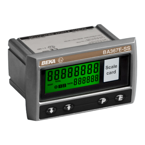
- Page 1 BA367E-SS Rugged one input Intrinsically safe Counter Issue 6 Issue: July 2019...
-
Page 2: Table Of Contents
4.3.2 Installation in Ex p panel enclosure 5. Installation 5.1 Location 5.2 Installation procedure 5.3 EMC 5.4 Counter earthing 5.5 Scale card The BA367E-SS is CE marked to show compliance with the European Explosive Atmospheres Directive 2014/34/EU and the European EMC Directive 2014/30/EU... - Page 3 CONTENTS CONTINUED 9. Accessories 9.1 Scale card 9.5 4/20mA output 9.5.1 Intrinsic safety 9.2 Tag information 9.5.2 System design 9.5.3 Configuration 9.3 Alarms 9.5.4 Access 4/20mA output 9.3.1 Solid state output sub-menu: 4-20 oP 9.3.2 Intrinsic safety 9.5.5 Enable 4/20mA output: EnbL 9.3.3 Configuration summary 9.5.6 Select rate or total source:...
-
Page 5: Description
This instruction manual supplements the abbreviated instruction sheet supplied with each instrument. The BA367E-SS has been certified intrinsically safe for use in gas and dust hazardous areas by Notified Body Intertek Testing and Certification Ltd and complies with the European ATEX Directive 2014/34/ EU. -
Page 6: Initialisation
2.1 Initialisation 2.3 Displays Each time power is applied to a BA367E-SS Counter The BA367E-SS Counter has two digital displays initialisation is performed. After a short delay the and associated annunciators, plus a pulse input following display sequence occurs: indicator as shown on the front page of this manual. -
Page 7: Intrinsic Safety Certification
This section of the instruction manual describes This means that when installed in an Ex e, Ex n, ATEX installations in explosive gas atmospheres Ex p or Ex t panel enclosure the BA367E-SS conforming with EN60079-14 Electrical installations remains an intrinsically safe instrument and must design, selection and erection. - Page 8 EN60079-11), which allows them to be ignored and not documented when assessing an intrinsic safe The input safety parameters of terminals 1 and 2 system. are: 28V dc When terminals 3 & 4 are not linked, the BA367E-SS 200mA dc Counter input terminals comply with 0.84W...
- Page 9 NAMUR compliant proximity detector is less than 7.5V. 3.6 Remote reset terminals The BA367E-SS Counter may be reset to zero or to the reset value by connecting the reset terminals RS1 and RS2 together for more than one second.
-
Page 10: System Design For Hazardous Areas
BA367E-SS Counter. Terminals 2, 6 and RS2 of the BA367E-SS Counter are internally connected together. If any of these terminals are earthed, as shown in Figs 2 & 3, the other common terminals should only be connected to the same earth, i.e. -
Page 11: Pulse Input
4.1.2 Pulse input 4.1.5 Open collector input As shown in Fig 2 the BA367E-SS can count pulses Most open collector sensors located in the same from a wide variety of sensors in the hazardous hazardous area as the BA367E-SS Counter may be area, or from the safe area as shown in Fig 3. -
Page 12: Remote Reset
Counter providing it and the associated wiring can withstand a 500V rms insulation test to earth. No Zener barrier is required. A BA367E-SS may also be remotely reset from the safe area. Any switch may be used but a Zener... -
Page 13: Pulse Input
4.2.2 Pulse input 4.2.5 Open collector input As shown in Fig 4 the BA367E-SS can count pulses Most open collector sensors located in the same from a wide variety of sensors in the hazardous hazardous area as the BA367E-SS Counter may be area, or from the safe area as shown in Fig 5. -
Page 14: Remote Reset
4.2.8 Remote reset 4.3 Use in an Ex e or Ex p panel enclosure The BA367E-SS Counter may be remotely reset by located in Zone 1 or Zone 2. connecting terminals RS1 & RS2 together for more BA367E-SS ATEX EC-Type Examination than one second. -
Page 15: Installation In Ex E Panel Enclosure
IP30 cover carrying a warning label 'Do not open when energised'. The power dissipation within an BA367E-SS fitted with operational alarms and a backlight is normally about 350mW. In the very unlikely event that all three circuits fail to the worst case condition at the same time, the total power dissipation rises to 2.5W... -
Page 16: Installation
Although the front of the BA367E-SS has IP66 protection, it should be shielded from continuous direct sunlight and severe weather conditions. The BA367E-SS may be located in Zone 0, 1 or 2 providing that the operating temperature is between –40°C and +60°C and the installation complies with the certification requirements. -
Page 17: Emc
Fig 10 Terminals for field wiring 5.4 Counter earthing Fig 11 Inserting flexible strip carrying scale card into The BA367E-SS has an M4 earth stud on the rear slot at the rear of the Tachometer. panel which should be electrically connected to the panel enclosure in which the instrument is mounted, or to the plant equipotential conductor. -
Page 18: Configuration Structure
6.1 Configuration structure Fig 12 shows the configuration structure of the BA367E-SS Counter. The pulse input is passed to the 5CALE. r and 5CALE. t functions allowing the independent rate and total displays to have different engineering units. -
Page 19: Accessing The Configuration Functions
Fig 13. applied to the pulse input to prevent false counting: When returning to the display mode following dEFAuLt reconfiguration, the BA367E-SS Counter will display HEAVY dAtA followed by 5AVE while the new information is LiGHt stored in permanent memory. - Page 20 The total display is independent of Defines a preset number to which the rate display. the total display will be set when the See section 6.12 BA367E-SS Counter is locally or remotely reset. Enables instrument to count down from a Rate scale factor 5CALE .
- Page 21 & and * buttons are operated simultaneously for more Reset to factory defaults r5Et dEF than three seconds in the display Returns the BA367E-SS Counter to mode. the factory defaults shown in section See section 6.19 To prevent accidental use the...
-
Page 24: Input: Input
Light 400µs 5µs switch contacts or open collector sensors, terminals 3 & 4 of the BA367E-SS should be linked together. maximum counting frequency BA367E-SS depends upon the debounce level 3. To count correctly, the input pulse must fall... -
Page 25: Input Pulse Counting Edge: Cnt Edge
6.7 Input pulse counting edge: Cnt EdgE 6.10 Lower display: di5P-2 This function defines whether the BA367E-SS This function turns the lower display on or off. Counter is incremented/decremented on the leading When turned off, the BA368E will only have one or trailing edge of an input pulse. -
Page 26: Total Scale Factor: 5Cale . T
When the total scale factor has been entered, press The timebase multiplies the rate display by 1, 60 or to return to the 5CALE . T prompt in the 3,600 depending upon whether the BA367E-SS configuration menu. Counter is required to display rate per second, per minute or per hour. -
Page 27: Direction Of Count: Up Or Dn
CLr VAL, the Second Magnitude of step digit change which will BA367E-SS will count down from the reset value to produce a rapid zero. response To check or change the count direction select uP or dn from the configuration menu and press ( which will reveal the present setting. -
Page 28: Local Total Reset: Clr Tot
[see section 6.17] while the total display, but is not reset when the total the BA367E-SS Counter is in the display mode by display is reset. The grand total may be viewed in operating... -
Page 29: Reset Configuration To Factory Defaults: R5Et Def
While resetting the BA367E-SS initially has default factory configuration. BA367E-SS Counter will display - - - - - - - - before automatically returning to the display mode If after accessing the configuration menu the interval when the operation is complete. -
Page 30: Update
Step 7 Enter the total scale factor reading display In this example the proximity detector BA367E-SS is only to be updated every produce four pulses per pump stroke. 3 seconds. The BA367E-SS is required to display Select uPdAtE from the configuration thousands of pump strokes therefore the menu and press (. - Page 31 5AVE while the configuration changes are stored in permanent memory. The BA367E-SS was assumed to initially have factory default configuration, therefore the counting edge, counting direction, local total and local grand total resets were not reconfigured as they already complied with the requirements for this example.
-
Page 32: Maintenance
28V on terminals Note: Terminals 2, 1 & 2 with If a BA367E-SS Counter fails after it has been 6 & RS2 are terminal 1 functioning correctly, the following table may help to interconnected positive. -
Page 33: Accessories
When the BA367E-SS power supply is turned off or Scale card disconnected, alarm outputs will open irrespective of whether normally open or normally closed outputs Tag number have been selected. -
Page 34: Configuration Summary
See section 9.3.10 9.3.3 Configuration summary Alarm silence time When a BA367E-SS Counter is supplied with alarms Defines the time that the alarm output the configuration menu is extended as shown in remains in the non-alarm condition Fig 16. -
Page 35: Alarm Enable: Enbl
9.3.4 Alarm enable: EnbL 9.3.5 Type of alarm: tYPE This function allows the alarm to be enabled or Alarm 1 and Alarm 2 are totally independent, both disabled without altering alarm may be rate or total alarms, or one may be parameters. -
Page 36: Setpoint Adjustment
All the setpoints are adjusted in the same way, for example, to adjust the setpoint of Alarm 1 which has e.g. A BA367E-SS Counter configured to display a been configured to operate on the rate display. rate of 0 to 5000, with a high alarm set at 4000 and hysteresis of 100 will perform as follows: Using the &... -
Page 37: Flash Display When Alarm Occurs: Fl5H
In addition to the two alarm annunciators on the left display mode Access to the two alarm setpoints from the hand side of the BA367E-SS Counter display which show the status of both alarms, this function BA367E-SS Counter’s display mode is obtained by... -
Page 38: Pulse Output
4/20mA output. 9.4.2 System design The BA367E-SS Counter pulse output is a passive The BA367E-SS Counter can be supplied with a circuit i.e. not powered, but it is totally isolated from factory fitted opto-isolated solid state pulse output. -
Page 39: Configuration
Fig 18 Transferring pulse output to safe area using Zener barriers 9.4.3 Configuration When a BA367E-SS Counter is supplied with an optional pulse output the configuration menu is extended as shown in Fig 19. The pulse output sub-menu allows the source of the output pulse to be selected in the 5ourCE sub- function. -
Page 40: Source Of Pulse Output: 5Ource
) button to return to output. diVidE prompt. The BA367E-SS Counter can be supplied with a Note: This function only appears in the sub-menu factory fitted galvanically isolated 4/20mA current when the output pulse is derived from the sink which may be configured to represent the rate the total display. -
Page 41: System Design
To determine the maximum permissible cable 9.5.3 Configuration parameters, these figures should be subtracted from When a BA367E-SS Counter is supplied with an the maximum cable capacitance and inductance optional 4/20mA output the configuration menu is specified by the certificate for the Zener barrier or extended as shown in Fig 20. -
Page 42: Enable 4/20Ma Output: Enbl
4/20mA output The 4/20mA output current can represent the current will continue to flow when the BA367E-SS Counter’s rate or total display and this BA367E-SS Counter supply fails or is should be defined before any other 4/20mA current turned off. - Page 43 A1.1 Zones, and Maximum Surface Temperature The BA367E-SS has IP66 front of panel protection The BA367E-SS has been ATEX certified as Group and a gasket is provided to seal the joint between II, Category 1D Ex ia IIIC T80ºC Da apparatus, Ta - the instrument and the mounting panel thus 40 to 60°C.
- Page 44 Zone 21 or Zone 22. apparatus is usually installed in the safe area, but if Installation of a BA367E-SS Counter in an Ex t IIIC suitably certified may be mounted in the same Ex tc panel enclosure does not invalidate the Ex t panel's...
- Page 45 IP6X protection. This means that when installed in an Ex e, Ex n, Ex p or Ex t panel enclosure the BA367E-SS remains an intrinsically safe instrument and must comply with the installation requirements shown in...
- Page 46 Appendix 3 ETL & cETL certification for A3.2 Nonincendive approval installations in USA and Canada The BA367E-SS rugged Counter also has ETL and cETL nonincendive approval allowing installation in A3.0 cETL Mark Division 2 hazardous (classified) locations without For installations in the USA and Canada, the the need for Zener barriers or galvanic isolators.
Need help?
Do you have a question about the BA367E-SS and is the answer not in the manual?
Questions and answers