Table of Contents
Advertisement
Quick Links
Advertisement
Table of Contents

Related Manuals for BEKA BA367NE


Summary of Contents for BEKA BA367NE
- Page 1 BA367NE One input Ex nA and Ex tc Counter Issue 7 Issue: July 2019...
-
Page 2: Table Of Contents
8.1 Fault finding during commissioning 8.2 Fault finding after commissioning 8.3 Servicing 8.4 Routine maintenance 8.5 Guarantee 8.6 Customer comments The BA367NE is CE marked to show compliance with the European Explosive Atmospheres Directive 2014/34/EU and the European EMC Directive 2014/30/EU... - Page 3 CONTENTS CONTINUED 9. Accessories 9.1 Scale card 9.5 4/20mA output 9.5.1 Ex nA certification 9.2 Tag information 9.5.2 Configuration 9.5.3 4/20mA output: 4-20 oP 9.3 Alarms 9.5.4 Enable 4/20mA output: EnbL 9.3.1 Solid state output 9.5.5 Select rate or total source: 9.3.2 Ex nA certification 4-20tYPE 9.3.3 Configuration summary...
-
Page 4: Description
1. DESCRIPTION 2.1 Initialisation This rugged Ex nA and Ex tc certified, one input Each time power is applied to a BA367NE Counter Counter may be configured to count input pulses initialisation is performed. After a short delay the from a wide variety of sensors in a Zone 2 or following display sequence occurs: Zone 22 hazardous area. -
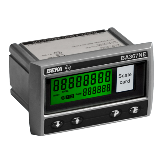
Page 5: Displays
2.3 Displays The BA367NE Counter has two digital displays and associated annunciators, plus a pulse input indicator as shown on the front cover of this manual. Total Shows the total pulse count on the display upper eight digit display. May be reset to zero via front panel push buttons or by a remote reset switch. -
Page 6: Certification
UK the local Code of Practice should be consulted. These special conditions for safe use can be satisfied by mounting the BA367NE in an Ex n, Ex e or Ex p panel enclosure. For ATEX Category 3 3.2 Zones, gas groups and T rating... -
Page 7: Remote Reset Terminals
BA367NE may also be connected to suitably 3.6 Remote reset terminals protected and certified equipment located in Zone 1. The BA367NE total display my be reset to zero by This is illustrated in Fig 5 and explained in connecting the external reset terminals RS1 and Application Guide AG310. -
Page 8: Pulse Input
4.1 Power supply 4.2 Pulse input The BA367NE Counter requires a minimum of 10V The BA367NE can count and display the total between terminal 1 & 2 and consumes: number of input pulses received from a wide variety of sensors located in a Zone 2 hazardous area or in... -
Page 9: Input Switching Thresholds
A BA367NE may also be remotely reset from the bounce being counted. See section 6.6. safe area. Any switch may be used. Fig 4 illustrates how a BA367NE may be reset from both the safe 4.2.3 Open collector input and the hazardous area. -
Page 10: Installation
IP66 ingress protection. The BA367NE has IP20 rear protection. Although the front of the BA367NE Counter has IP66 protection, it should be shielded from continuous direct sunlight and severe weather conditions. Fig 6 shows the overall dimensions of the BA367NE together with the recommended panel enclosure cut- out dimensions. -
Page 11: Counter Earthing
Counter rear 5.3 Counter earthing panel. The BA367NE has an M4 earth stud on the rear panel which should be electrically connected to the panel enclosure in which the Counter is mounted, or to the plant equipotential conductor. -
Page 12: Configuration Structure
Note: While the instrument is being configured counting continues so that any input pulses occurring during this time are recorded. 6.1 Configuration structure Fig 10 shows the calibration structure of the BA367NE Counter. The pulse input is passed to the functions allowing 5CALE. r 5CALE. t independent rate and total displays to have different engineering units. -
Page 13: Summary Of Configuration Functions
LiGHt See section 6.6 If after accessing the configuration menu the interval between operating any front panel push button exceeds one minute, the BA367NE will automatically Input pulse counting edge Cnt EdGE return to the display mode and any configuration Defines whether the Counter is changes will not be stored in permanent memory. - Page 14 The total display is independent of Defines a preset number to which the rate display. the total display will be set when the See section 6.12 BA367NE Counter is locally or remotely reset. Enables instrument to count down from a Rate scale factor 5CALE .
- Page 15 & and * buttons are operated simultaneously for more Reset to factory defaults r5Et dEF than 2 seconds in the display mode. Returns the BA367NE Counter to See section 6.19 the factory defaults shown in section To prevent accidental use the request...
-
Page 18: Input: Input
Light 400µs 5µs switch contacts or open collector transducers, terminals 3 & 4 of the BA367NE should be linked together. The maximum counting frequency of the BA367NE depends upon the debounce level selected, the 3. To count correctly, the input pulse must fall shape of the input pulse and its amplitude. -
Page 19: Input Pulse Counting Edge: Cnt Edge
This function defines whether the BA367NE Counter This function turns the lower display on or off. is incremented/decremented on the leading or When turned off, the BA367NE will only have one trailing edge of an input pulse. eight digit display which may be configured in the di5P-1 function to show the total count or rate. -
Page 20: Total Scale Factor: 5Cale . T
The timebase multiplies the rate display by 1, 60 or When the total scale factor has been entered, press 3,600 depending upon whether the BA367NE ( to return to the 5CALE . T prompt in the Counter is required to display rate per second, per configuration menu. -
Page 21: Direction Of Count: Up Or Dn
During commissioning it is recommend that initially operated. This allows the BA367NE to be used as a the second digit is set to 0 (off) and the first digit is preset down-counter. -
Page 22: Local Total Reset: Clr Tot
[see section 6.17] the total display, but is not reset when the total while the BA367NE Counter is in the display mode display is reset. The grand total may be viewed in by operating the & and * push buttons simultaneously for more than two seconds. -
Page 23: Reset Configuration To Factory Defaults: R5Et Def
While resetting the BA367NE initially has default factory configuration. BA367NE Counter will display - - - - - - - - before automatically returning to the display mode when the If after accessing the configuration menu the interval operation is complete. - Page 24 Step 3 Select display update Step 7 Enter the total scale factor To aid reading the display the BA367NE In this example the proximity detector is only to be updated every 3 seconds. produce four pulses per pump stroke. Select uPdAtE from the configuration...
- Page 25 5AVE while the configuration changes are stored in permanent memory. The BA367NE was assumed to initially have factory default configuration, therefore the counting edge, counting direction, local total and local grand total resets were not reconfigured as they already complied with the requirements for this example.
-
Page 26: Maintenance
Incorrect rate indicator rotating display calibration 5CALE. r but incorrect rate t-bA5E If a BA367NE fails after it has been functioning display. correctly, the following table may help to identify the cause of the failure. Pulse indicator Incorrect total indicator rotating display 5CALE. -
Page 27: Routine Maintenance
8.5 Guarantee Instruments which fail within the guarantee period should be returned to BEKA associates or our local agent. It is helpful if a brief description of the fault symptoms is provided. 8.6 Customer comments... -
Page 28: Accessories
9.1 Scale card irrespective of the display update time selected. The BA367NE Counter has a window on the right This may result in an alarm being delayed for up to hand side of the display through which a scale card half a second after the rate or total has exceeded the showing the units of measurement is visible. -
Page 29: Configuration Summary
When enabled, alternates the rate or 9.3.3 Configuration summary total display between process value and When a BA367NE is supplied with alarms the alarm reference Al1 or Al2 when an configuration menu is extended as shown in Fig 14. alarm output is activated. -
Page 30: Alarm Enable: Enbl
This function allows the alarm to be enabled or Each single pole alarm output may be open or disabled without altering alarm closed in the non-alarm condition. When the BA367NE power supply turned parameters. Using the & or * push button select disconnected, alarm output(s) -
Page 31: Alarm Silence Time: 5Il
The Counter's alarm annunciator will start flashing After an alarm has occurred, operating the ( immediately an alarm condition occurs and will button will cause the alarm output to revert to the continue for the delay time, after which the alarm non-alarm condition for the programmed alarm output will be activated and the alarm annunciator silence time. -
Page 32: Access Setpoint: Ac5P
Once within the menu pressing the & or * buttons provides direct access to the alarm setpoints from will toggle the display between the two alarm the display mode, i.e. when the BA367NE is setpoint prompts 5P1x and 5P2x. counting, by simultaneously operating the ( and * buttons. -
Page 33: Pulse Output
60Ω + 3V. direct: 9.4 Pulse output Annunciator continuously activated The BA367NE can be supplied with a factory fitted isolated pulse output for retransmitting pulses to other instruments. Note: Only one of the three output options can be fitted to a BA367NE Counter. -
Page 34: Ex Na Certification
This allows the pulse output to be connected to any 9.4.2 Pulse output configuration: PuL5E oP dc circuit providing that in normal operation the When a BA367NE is supplied with a factory fitted maximum supply voltage is not greater than 30V dc. pulse output the instrument configuration menu is extended as shown in Fig 18. -
Page 35: Source Of Pulse Output: 5Ource
9.4.4 Source of pulse output: 5ourCE Using the & or * push button select durAtion in The output pulse may be derived from: the pulse output sub-menu and press ( which will reveal the existing pulse duration. The value can be Incrementation of least significant 5CALEd changed by pressing the &... -
Page 36: 4/20Ma Output
9.5 4/20mA output To comply with the requirements of EN 60079-14 The BA367NE Counters can be supplied with a Electrical installations design, selection and erection, factory fitted isolated 4/20mA output which may be each of the wires entering the hazardous area configured to represent the rate or total display. -
Page 37: 4/20Ma Output: 4-20 Op
9.5.3 4/20mA output: 4-20 oP Access the Counter's configuration menu as described in section 6.2. Using the &or* push buttons scroll though the menu until 4-20 oP is displayed, pressing ( will then access the 4/20mA output sub-menu which is shown in Fig 20. 9.5.4 Enable 4/20mA output: EnbL This function allows the 4/20mA output to be disabled or enabled without altering any of the... - Page 38 Ex nA parameters, therefore all the electrical circuits shown in the main section of this manual may also be used for dust applications. 10.6 Backlight The BA367NE Counter can be supplied with a factory fitted backlight that produce green A1.1...
- Page 39 Appendix 2 IECEx certification has an 'X' suffix to show that special conditions for safe use are specified by the BA367NE Ex ic tc A2.0 The IECEx Certification Scheme certificate indicated by the certificate number's 'X' IECEx is a global certification scheme for explosion suffix.
- Page 40 USA and Canada A3.0 cETL Mark For installations in the USA and Canada, the BA367NE Counter has ETL and cETL Ex nA and Ex tc approval, Control Number 4008610. Copies of the Authorisation to Mark are available from the BEKA associates sales office and www.beka.co.uk...
Need help?
Do you have a question about the BA367NE and is the answer not in the manual?
Questions and answers