
Related Manuals for BEKA BA567E-SS


Summary of Contents for BEKA BA567E-SS
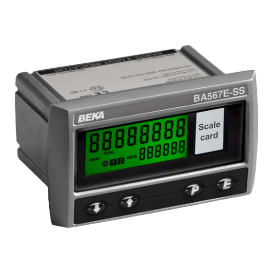
- Page 1 BA567E-SS Rugged one input General purpose Counter Issue 6 Issue: 6 July 2019...
-
Page 2: Table Of Contents
8.5.6 Display corresponding to 5.24 Display overflow 4mA output: 4 . 000 8.5.7 Display corresponding to 20mA output: 20 . 000 8.6 Display backlight The BA567E-SS is CE marked to show compliance with the European EMC Directive 2014/30/EU... -
Page 3: Description
( and * buttons are operated simultaneously. See 8.3.13 2.1 Initialisation Each time power is applied to a BA567E-SS Counter initialisation is performed. After a short delay the following display sequence occurs: All segments of the display are activated... -
Page 4: Displays
2.3 Displays The BA567E-SS Counter has two digital displays and associated annunciators, plus a pulse input indicator as shown on the front page of this manual. Total Shows the total pulse count on the display upper eight digit display. May be reset to zero via front panel push buttons or by a remote reset switch. -
Page 5: System Design
See section 5.6. 3.2 Pulse input As shown in Fig 2 the BA567E-SS can count pulses 3.3 Remote reset from a wide variety of sensors. The Counter's total display may be remotely reset to... -
Page 6: Installation
4. INSTALLATION 4.1 Location The BA567E-SS has a stainless steel case with a 10mm thick toughened glass window. The case provides 7J and the window 4J front of panel impact protection. The captive silicone gasket, which seals the joint between the instrument and the panel enclosure, ensures IP66 front of panel ingress protection. -
Page 7: Emc
Fig 5 Terminals for field wiring 4.4 Counter earthing The BA567E-SS has an M4 earth stud on the rear panel which should be electrically connected to the Fig 6 Inserting flexible strip carrying scale card into panel enclosure in which the instrument is mounted, slot at the rear of the Tachometer. -
Page 8: Configuration Structure
5.1 Configuration structure Fig 7 shows the configuration structure of the BA567E-SS Counter. The pulse input is passed to the 5CALE. r and 5CALE. t functions allowing the independent rate and total displays to have different engineering units. - Page 9 Fig 8. applied to the pulse input to prevent false counting: When returning to the display mode following dEFAuLt reconfiguration, the BA567E-SS Counter will display HEAVY dAtA followed by 5AVE while the new information is LiGHt stored in permanent memory.
- Page 10 The total display is independent of Defines a preset number to which the rate display. the total display will be set when the See section 5.12 BA567E-SS Counter is locally or remotely reset. Enables instrument to count down from a Rate scale factor 5CALE .
- Page 11 & and * buttons are operated simultaneously for more Reset to factory defaults r5Et dEF than three seconds in the display Returns the BA567E-SS Counter to mode. the factory defaults shown in section See section 5.19 To prevent accidental use the...
- Page 14 Light 400µs 5µs require energising i.e. proximity detectors, switch contacts or open collector sensors, terminals 3 & 4 of the BA567E-SS should be maximum counting frequency linked together. BA567E-SS depends upon the debounce level selected, the shape of the input pulse and its 3.
-
Page 15: Position Of The Decimal Points: Dp
5.7 Input pulse counting edge: Cnt EdgE 5.10 Lower display: di5P-2 This function defines whether the BA567E-SS This function turns the lower display on or off. Counter is incremented/decremented on the leading When turned off, the BA367E-SS will only have one or trailing edge of an input pulse. -
Page 16: Total Scale Factor: 5Cale . T
When the total scale factor has been entered, press The timebase multiplies the rate display by 1, 60 or to return to the 5CALE . T prompt in the 3,600 depending upon whether the BA567E-SS configuration menu. Counter is required to display rate per second, per minute or per hour. -
Page 17: Direction Of Count: Up Or Dn
CLr VAL, the Second Magnitude of step digit change which will BA567E-SS will count down from the reset value to produce a rapid zero. response To check or change the count direction select uP or dn from the configuration menu and press ( which will reveal the present setting. -
Page 18: Local Total Reset: Clr Tot
[see section 5.17] while the total display, but is not reset when the total the BA567E-SS Counter is in the display mode by display is reset. The grand total may be viewed in operating... -
Page 19: Reset Configuration To Factory Defaults: R5Et Def
While resetting the To prevent future total display overflows occurring BA567E-SS Counter will display - - - - - - - - the total scale factor 5CALE . t and the position of the before automatically returning to the display mode decimal point in the total display dP should be when the operation is complete. -
Page 20: Configuration Example
6. CONFIGURATION EXAMPLE Step 3 Select display update A BA567E-SS Counter is required to display the total reading display number of strokes that a reciprocating pump makes BA567E-SS is only to be updated every in thousands of strokes on the larger upper display 3 seconds. - Page 21 ( to reveal the current setting. Using the & or * button scroll through the three options and select The BA567E-SS was assumed to initially have tb-3600. Return to the t-bA5E prompt in factory default configuration, therefore the counting the configuration menu by pressing ).
-
Page 22: Maintenance
30V on terminals Note: Terminals 2, 1 & 2 with If a BA567E-SS Counter fails after it has been 6 & RS2 are terminal 1 functioning correctly, the following table may help to interconnected positive. -
Page 23: Accessories
Scale card When the BA567E-SS power supply is turned off or Tag number disconnected, alarm outputs will open irrespective of whether normally open or normally closed outputs Backlight have been selected. -
Page 24: Configuration Summary
Determines whether the single pole alarm output is open or closed in the 8.3.2 Configuration summary non-alarm condition. When a BA567E-SS Counter is supplied with alarms See section 8.3.7 the configuration menu is extended as shown in Fig 11. Each alarm may be configured to operate... -
Page 25: Alarm Enable: Enbl
8.3.3 Alarm enable: EnbL 8.3.4 Type of alarm: tYPE This function allows the alarm to be enabled or Alarm 1 and Alarm 2 are totally independent, both disabled without altering alarm may be rate or total alarms, or one may be parameters. -
Page 26: Setpoint Adjustment: 5P1X & 5P2X
All the setpoints are adjusted in the same way, for example, to adjust the setpoint of Alarm 1 which has e.g. A BA567E-SS Counter configured to display a been configured to operate on the rate display. rate of 0 to 5000, with a high alarm set at 4000 and hysteresis of 100 will perform as follows: Using the &... -
Page 27: Flash Display When Alarm Occurs: Fl5H
In addition to the two alarm annunciators on the left display mode Access to the two alarm setpoints from the hand side of the BA567E-SS Counter display which show the status of both alarms, this function BA567E-SS Counter’s display mode is obtained by... -
Page 28: Pulse Output
To adjust an alarm setpoint select 5P1x or 5P 2x and 8.4.1 System design press ( which will reveal the current setting. The The BA567E-SS Counter's optional pulse output is a passive circuit i.e. not powered, but it is totally flashing digit of the setpoint may be adjusted using isolated from all other Counter circuits. -
Page 29: Access Pulse Output Sub-Menu: Pul5E Op
8.4.2 Configuration 8.4.3 Access Pulse output sub-menu: PuL5E oP When a BA567E-SS Counter is supplied with an Access to the BA567E-SS Counter configuration optional pulse output the configuration menu is menu as described in section 5.2. Using the & and extended as shown in Fig 14. -
Page 30: Source Of Pulse Output: 5Ource
8.4.5 Source of pulse output: 5ourCE 8.4.7 Output pulse width: durAtion The output pulse may be derived from: When the output pulse is derived from the total display, the pulse width is defined by this function. One of 11 pulse widths may be selected in Output is a duplicate of the input dirECt milliseconds:... -
Page 31: 4/20Ma Output
Only one of the following accessories may be fitted: dual alarms, pulse output or 4/20mA output. The BA567E-SS Counter can be supplied with a factory fitted galvanically isolated 4/20mA current sink which may be configured to represent the rate or total display. -
Page 32: Display Backlight
8.5.6 Display which corresponds to 4mA 8.6 Display backlight output: 4 . 000 The BA567E-SS Counter can be supplied with a factory fitted backlight that produce green The BA567E-SS Counter display which corresponds to a 4.000mA output current is defined by this illumination enhancing display contrast and enabling it to be read at night or in poor lighting conditions.
Need help?
Do you have a question about the BA567E-SS and is the answer not in the manual?
Questions and answers