Sign In
Upload
Manuals
Brands
Enotec Manuals
Analytical Instruments
OXITEC 5000 Series
Enotec OXITEC 5000 Series Manuals
Manuals and User Guides for Enotec OXITEC 5000 Series. We have
1
Enotec OXITEC 5000 Series manual available for free PDF download: Installation And Operation Manual
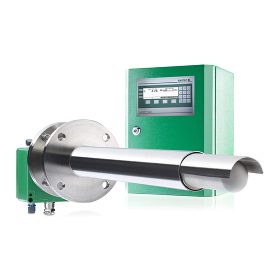
Enotec OXITEC 5000 Series Installation And Operation Manual (62 pages)
O2 Analyzer System
Brand:
Enotec
| Category:
Analytical Instruments
| Size: 4 MB
Table of Contents
Table of Contents
3
1 System Description
4
System Overview
4
Measuring Principle
6
Intended Use
6
Safety Hazards
6
Disruption of the Process
6
Storage Instructions
6
Name Plates
7
2 Installation
8
Installation Requirements for Electronic Unit
8
Installation of Probe Signal Cable FEP-0001
9
Access to the Terminals
10
Ferrite Sleeves (EMC)
10
Wiring Diagram of the Electronic Unit
11
OXITEC® 5000 Wiring Diagram
12
Installation of the Probe
13
Mounting of the Probe
14
Mounting a Probe with Cooling Protection Tube
15
Adjusting the V-Shield
15
Electrical Connections of the Probe
16
Requirements for Pneumatic Tube FEP-0002
16
Preparation of the Pneumatic Cable
17
Gas Plans
17
Pneumatic Connections of the Probe
18
Pneumatic Connections of Electronic Unit
19
3 Initial Operation
20
Checklist before Commissioning the System
20
System Power up
20
Display - Probe Heating Phase
20
Display - Measuring Mode
21
Keypad and Display
21
Status Leds
21
Softkey Symbols
21
System Code
21
4 Software Overview and Explanations
22
Menu Overview - SYS-MENU
22
Software Explanations - SYS-MENU
25
O 2 Measuring Ranges (Scaling)
25
Measuring Value Averaging for
25
Ma Output on System Errors
25
O 2 Limit Alarm Settings
25
O 2 Sensor Calibration Values
26
Time Per Test Gas Apply
26
Delay Time to Process
26
Automatic Calibration (ACAL)
26
Automatic Calibration Settings
26
Enotec Remote
27
Measuring Units
27
Language
27
Change System Code
27
Load Factory Settings
27
Service (Factory Service Settings)
28
Calibration Menu
28
Calibration Menu - Display Overview
28
1-Point Calibration (Manual)
29
System Checks
30
5 Service and Maintenance
31
Exchange Fuses
31
Flow Rates for Test Air and Reference Air
31
Adjusting Flow Rate (Integrated Pneumatics)
32
Position of the Adjustment Valves
33
Adjusting Flow Rate (SME-54)
33
Replacing the Filter
34
Remove Old Filter
34
Cement in New Filter
34
Replacing the Probe
35
Replacing the O Sensor
35
Exchange of Probe Inner Parts
37
Relay Outputs / Functions and Correlation
38
Digital Inputs
39
Stability Criteria for Calibration
39
Reaction Time of the Ma Output
39
Extension Modules
39
Maintenance Intervals
39
6 Status Messages
40
Error Messages
40
Alarm Messages
41
Maintenance Messages
42
7 Troubleshooting
43
Technical Data
44
Technical Specifications - Electronic Unit
44
Technical Specifications - Probe
45
Gas Supply - Systems with Instrument Air
46
Dimensional Drawings
47
Dimensions of Electronic Unit Housing Versions
47
Probe Dimensions
48
Counter Flange Dimensions
51
Dimensions of Protection Tube Flanges
53
Spare Parts
54
Probe Components - KES-132X
54
Probe Components - KES-200X
55
Probe Components - KES-500X
56
Probe Inner Parts Assembly
57
Mounting Plates of the Electronic Unit
58
Display Board
59
Warranty
60
Declaration of Conformity
61
Index
62
Advertisement
Advertisement
Related Products
Enotec AQUATEC 1000
Enotec COMTEC 6000
Enotec OXITEC 5000+
Enotec OXITEC ECONOMY
Enotec Categories
Measuring Instruments
Analytical Instruments
More Enotec Manuals
Login
Sign In
OR
Sign in with Facebook
Sign in with Google
Upload manual
Upload from disk
Upload from URL