Table of Contents

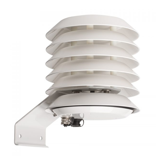
Summary of Contents for Met One Instruments BX-597A
- Page 1 MODEL BX-597A Temperature / Relative Humidity / Barometric Pressure Sensor Operation Manual Document No. BX-597A-9800 Rev C Met One Instruments, Inc 1600 NW Washington Blvd. Grants Pass, Oregon 97526 Tel: (541) 471-7111 Fax: (541) 471-7116...
- Page 2 Copyright Notice Model BX-597A Relative Humidity / Temperature / Barometric Pressure Sensor Manual. © Copyright 2020 Met One Instruments, Inc. All Rights Reserved Worldwide. No part of this publication may be reproduced, transmitted, transcribed, stored in a retrieval system, or translated into any other language in any form by any means without the express written permission of Met One Instruments, Inc.
- Page 3 Safety Notice The contents of this manual have been checked against the hardware and software described herein. Since deviations cannot be prevented entirely, we cannot guarantee full agreement. However, the data in this manual is reviewed regularly and any necessary corrections included in subsequent editions.
-
Page 4: Table Of Contents
5.2. Siting ........................3 5.3. Wiring ........................3 Specifications ......................4 Sensor Verification ....................5 Serial Communications ..................5 Maintenance ......................7 10. Service ........................7 11. Wiring Diagrams ....................8 12. Terminal Mode Commands ................10 BX-597A-9800 Manual Rev C... -
Page 5: Introduction
3. Initial Inspection Upon receipt of the Model BX-597A, inspect the packaging and contents for damage. If the packaging has arrived in a damaged condition file a claim with the shipping company and contact Met One Instruments, Inc. -
Page 6: Product Overview
The BX-597A ships from Met One Instruments pre-wired for digital output signals including RS- 232 and RS-485. The BX-597A also includes voltage outputs for AT/RH/BP, and an ID voltage used by some Met One monitors and dataloggers to identify the sensor. The voltage outputs are 0-2.5VDC default and can be changed to 0-1VDC or 0-5VDC. -
Page 7: Installation
5.3. Wiring The BX-597A may be ordered with a 10547 analog output cable assembly, or 10548 digital output cable assembly (sold separately) for connection (Individual wire leads) of the BX-597A to a data logger, signal conditioner, or programmable logic controller. A detailed wiring diagram for each cable assembly is provided in Section 10: Wiring Diagrams. -
Page 8: Specifications
-50 °C to +70 °C Humidity: 0 to 100 % PHYSICAL Diameter: 7 in (178 mm) Length: 8 in (203 mm) Weight: 5 lb (2.3 kg) (1) At 25°C BX-597A-9800 Manual Rev C Page | 4... -
Page 9: Sensor Verification
8. Serial Communications Serial Data Output The output of the BX-597A is a fixed length, comma delimited, serial data stream. The serial output is factory set for 9600 baud, no parity, 8 data bits, with 1 stop bit (N, 8, 1). - Page 10 Polled Data Mode (RS232 or RS485) The sensor can be set for polled data mode instead of continuous serial output, by setting the serial trigger string while in terminal mode (see Section 12 for command details). BX-597A-9800 Manual Rev C Page | 6...
-
Page 11: Maintenance
Return the sensor to Met One Instruments, Inc. for factory inspection and calibration. 10. Service The BX-597A is not field repairable and should be returned to the factory for service. Detailed calibration & service information and pricing are available from the Met One Instruments, Inc. -
Page 12: Wiring Diagrams
PIN NO WIRE COLOR WIRE LABEL DESCRIPTION +12VDC +9 to +36 VDC Black Signal Ground Orange Ana Gnd Analog Ground Brown RH Analog Output Green ID Voltage White BP Analog Output Blue AT Analog Output Page 8 BX-597A-9800 Manual Rev C... - Page 13 No Connection Unused Green SIG GND Signal Ground White RS-232 Tx RS-232 Transmit Brown RS-232 Rx RS-232 Receive Orange RS-485 - RS-485 signal - Yellow RS-485 + RS-485 signal + White/Brown Shield Earth Ground BX-597A-9800 Manual Rev C Page | 9...
-
Page 14: Terminal Mode Commands
Description Report the settings. Response 597A Settings Report Firmware, 10893, R1.0.0 Serial Number, I0002 Unit ID, 1 Baud Rate, 9600 AT Unit, C BP Unit, mbar ID – Request or Set the Location ID Page 10 BX-597A-9800 Manual Rev C... - Page 15 Set Output Interval in seconds.. Where i is the Interval. 0=No volunteered output, 1=Output every Second. No averaging. Response Description OI i On or Off Example OI<cr> OI 1<cr><lf> OI 0<cr> OI 0<cr><lf> PU - Pressure Units BX-597A-9800 Manual Rev C Page | 11...
- Page 16 Set the Temperature Units. e – Temperature Units 0-C,1-F. Response Description TU e-U e – Temperature Unit enumerator. u – Unit description Example TU<cr> TU 0-CIN<cr><lf> TU 1<cr> TU 1-F<cr><lf> RQ – Request Last Record Page 12 BX-597A-9800 Manual Rev C...
- Page 17 Response Description m, p, r m – Device model name. p – Firmware part number. r – Firmware revision. Example RV<cr> 597A, 10893, R1.0.0<cr><lf> QH – Display Record Header Command Description BX-597A-9800 Manual Rev C Page | 13...
- Page 18 Report data record header. Response AT(C),RH(%),BP(mbar),Status Page 14 BX-597A-9800 Manual Rev C...


Need help?
Do you have a question about the BX-597A and is the answer not in the manual?
Questions and answers