Digi LR54 User Manual
Hide thumbs
Also See for LR54:
- User manual (1113 pages) ,
- Hardware reference manual (21 pages) ,
- Quick start manual (2 pages)
Table of Contents
Advertisement
Quick Links
Advertisement
Table of Contents

Related Manuals for Digi LR54


Summary of Contents for Digi LR54
- Page 1 LR54 User Guide Firmware version 21.5...
-
Page 2: Revision History-90002386
Revision history—90002386 Revision Date Description Not released. Initial release of DigiLR54 firmware version 20.5. June 2020 LR54 User Guide... - Page 3 Digi Remote Manager. Added the ability to select Digi aView as the cloud service. Added the ability to duplicate firmware to copy the active firmware to the secondary firmware partition.
- Page 4 Admin CLI to view custom scripts and applications configured in the device, along with their status. Added the system scripts stop command to the Admin CLI to stop a custom script or application. LR54 User Guide...
- Page 5 Revision Date Description Release of Digi LR54 firmware version 20.11: December 2020 Modem firmware update commands added to the Admin CLI. Network bridging enhanced to use the MAC address of the first active device listed in Network > Bridges >...
- Page 6 Added a link to User Guide under the User menu in the Web UI. Release of Digi LR54 firmware version 21.2: March 2021 Location services added, including: The ability to define a static latitude and longitude as a location for the device.
- Page 7 Revision Date Description April 2021 Added IFETEL certification. LR54 User Guide...
- Page 8 Revision Date Description Release of Digi LR54 firmware version 21.5: June 2021 Wi-Fi enhancements: Added support for WPA3 Wi-Fi encryption: WPA2/WPA3 Personal WPA3 Enhanced Open WPA3 Personal Added support for WPA and WPA/WPA2 mised mode with TKIP. Cellular enhancements: Added support for modem firmware update to the Admin CLI.
- Page 9 Added the default digi.device local domain. Trademarks and copyright Digi, Digi International, and the Digi logo are trademarks or registered trademarks in the United States and other countries worldwide. All other trademarks mentioned in this document are the property of their respective owners.
- Page 10 Contact us at +1 952.912.3444 or visit us at www.digi.com/support. Feedback To provide feedback on this document, email your comments to techcomm@digi.com Include the document title and part number (LR54 User Guide, 90002386 H) in the subject line of your email. LR54 User Guide...
-
Page 11: Table Of Contents
What's new in Digi LR54 version 21.5 Digi LR54 Quick Start Step 1: Connect your device Step 2: Connect DC power Step 3: Set up access to Digi Remote Manager Step 4: Register your device Step 5: Complete setup Step 6: Configure cellular APN... - Page 12 Change the default password for the admin user Reset default SSIDs and pre-shared keys for the preconfigured Wi-Fi access points Configuration methods Using Digi Remote Manager Access Digi Remote Manager Using the web interface Log out of the web interface...
- Page 13 Routing IP routing Configure a static route Delete a static route Policy-based routing Configure a routing policy Example: Dual WAN policy-based routing Example: Route traffic to a specific WAN interface based on the client MAC address Routing services LR54 User Guide...
- Page 14 Allow remote access for web administration and SSH Configure the web administration service Configure SSH access Use SSH with key authentication Generating SSH key pairs Configure telnet access Configure DNS Show DNS server Simple Network Management Protocol (SNMP) LR54 User Guide...
- Page 15 Use Python to respond to Digi Remote Manager SCI requests Use digidevice runtime to access the runtime database Use Python to upload the device name to Digi Remote Manager Use Python to access the device location data The digidevice led submodule...
- Page 16 Terminal Access Controller Access-Control System Plus (TACACS+) TACACS+ user configuration TACACS+ server failover and fallback to local authentication Configure your LR54 device to use a TACACS+ server Remote Authentication Dial-In User Service (RADIUS) RADIUS user configuration RADIUS server failover and fallback to local configuration...
- Page 17 Reboot your LR54 device Reboot your device immediately Schedule reboots of your device Erase device configuration and reset to factory defaults Configure the LR54 device to use custom factory default settings Configuration files Save configuration changes Save configuration to a file...
- Page 18 Use the ping command to troubleshoot network connections Ping to check internet connection Stop ping commands Use the traceroute command to diagnose IP routing problems Digi LR54 regulatory and safety statements RF exposure statement Federal Communication (FCC) Part 15 Class B Radio Frequency Interference (RFI) (FCC 15.105)
- Page 19 Example: Create a new user by using the command line Example: Configure multiple WANs and LANs by using the command line Command line reference analyzer help mkdir modem modem puk status [imei STRING] [name STRING] modem scan [imeiSTRING] [nameSTRING] more ping reboot show system traceroute LR54 User Guide...
-
Page 20: What's New In Digi Lr54 Version 21.5
What's new in Digi LR54 version 21.5 Release of Digi LR54 firmware version 21.5: Wi-Fi enhancements: Added support for WPA3 Wi-Fi encryption: WPA2/WPA3 Personal WPA3 Enhanced Open WPA3 Personal Added support for WPA and WPA/WPA2 mised mode with TKIP. Cellular enhancements: Added support for modem firmware update to the Admin CLI. - Page 21 What's new in Digi LR54 version 21.5 Added the ability to configure how many times a SureLink test must run, and must fail, before the interface is restarted or the device is rebooted. Added the ability to configure how many times a SureLink test must pass before an interface is considered to be working.
-
Page 22: Digi Lr54 Quick Start
2. Attach cellular antennas. Securely finger tighten each antenna to the threaded barrel using the nut at the base of the antenna. 3. Use an Ethernet cable connect the LR54's WAN/ETH1 port to the internet, such as a home LR54 User Guide... -
Page 23: Step 2: Connect Dc Power
LAN Ethernet port in an office environment. Step 2: Connect DC power Step 3: Set up access to Digi Remote Manager If you already have a Digi Remote Manager account, skip to Register your device. If you prefer to configure the device locally rather than using Remote Manager, see Configuration and management in the LR54 User Guide. -
Page 24: Step 5: Complete Setup
Digi LR54 Quick Start Step 5: Complete setup Step 5: Complete setup 1. The device should connect within a couple of minutes. 2. If newer firmware is available, Remote Manager will prompt you to update the device. Click Update to update the firmware. Remote Manager will perform the update in the background and let you know when the device is up to date. -
Page 25: Digi Lr54 Hardware Reference
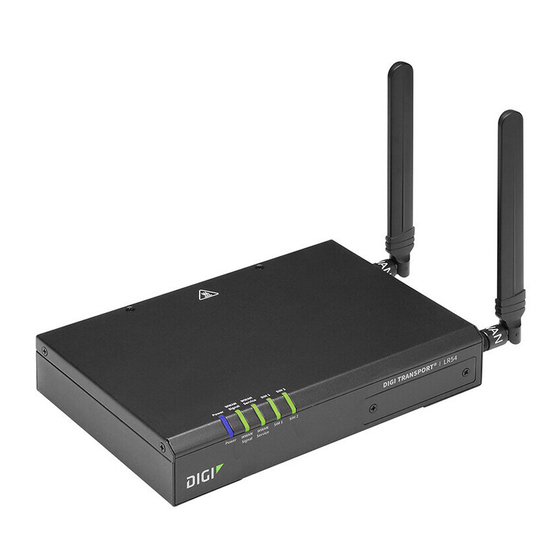
For a detailed list of Digi LR54 hardware specifications, see Digi LR54 specifications. Digi LR54 front and back views The following figures show front and back views of the Digi LR54. 1. Secondary Wi-Fi antenna connector (Wi-Fi-enabled models only). 2. Secondary cellular antenna. 3. LEDs (see... -
Page 26: Digi Lr54 Leds
10. Ethernet connectors. Digi LR54 LEDs The Digi LR54 has LEDs on the top front panel, and LEDs on the back of the model that indicate network links and activity. During bootup, the front-panel LEDs light up in sequence to indicate boot progress. -
Page 27: Digi Lr54 Serial Connector Pinout
Off: No Ethernet link detected. Solid green: Ethernet link detected. Blinking green: Indicates Ethernet traffic. Digi LR54 serial connector pinout The LR54 is a DTE device. The pinout for the DB9 serial connector is as follows: DTE signal Signal name RS232 signal... -
Page 28: Hardware Setup
Hardware setup This chapter contains the following topics: Install SIM cards Digi LR54 Mounting options Connect data cables Connect antennas Digi LR54 Mounting options LR54 User Guide... -
Page 29: Install Sim Cards
2. For high-vibration environments, apply a thin layer of dielectric grease to the SIM contacts. Note If the LR54 device is used in an environment with high vibration levels, SIM card contact fretting may cause unexpected SIM card failures. To protect the SIM cards, Digi strongly recommends that you apply a thin layer of dielectric grease to the SIM contacts prior to installing the SIM cards. -
Page 30: Attach Mounting Brackets To The Device
Hardware setup Digi LR54 Mounting options Attach mounting brackets to the device 1. Remove the four rubber feet from the bottom of the Digi LR54. 2. Using the four supplied M3x6mm screws, attach the mounting brackets. LR54 User Guide... -
Page 31: Mount The Digi Lr54 On A Wall
Hang the Digi LR54 on a wall Tighten two self-tapping screws to wall, but leave a small part of screw protruding from the wall. To hang the Digi LR54 on the wall, center the holes of the mounting brackets on the two wall- mounted screws. -
Page 32: Digi Lr54 Mounting Options
Dual cellular models: WWAN1-1/WWAN1-2 and WWAN2-1/WWAN2-2 Digi LR54 Mounting options The Digi LR54 Wall-Mount Kit (part number 78000001) is available separately for wall-mounting. It contains two mounting brackets and four screws. You will need to supply additional self-tapping screws and sleeve anchors as needed. -
Page 33: Mount The Digi Lr54 On A Wall
Hang the Digi LR54 on a wall Tighten two self-tapping screws to wall, but leave a small part of screw protruding from the wall. To hang the Digi LR54 on the wall, center the holes of the mounting brackets on the two wall- mounted screws. - Page 34 Hardware setup Digi LR54 Mounting options LR54 User Guide...
-
Page 35: Configuration And Management
Configuration and management This chapter contains the following topics: Review LR54 default settings Change the default password for the admin user Reset default SSIDs and pre-shared keys for the preconfigured Wi-Fi access points Configuration methods Using Digi Remote Manager Access Digi Remote Manager... -
Page 36: Review Lr54 Default Settings
Configuration and management Review LR54 default settings Review LR54 default settings You can review the default settings for your LR54 device by using the local WebUI or Digi Remote Manager: Local WebUI 1. Log into the LR54 WebUI as a user with Admin access. See Using the web interface for details. - Page 37 Firewall zone: Setup IP address LAN1 192.168.210.1/24 Default Link-local IP Bridge: Firewall zone: Setup IP address LAN1 169.254.100.100/16 Wi-Fi (available Wi-Fi access point: Digi AP (Wi- Wi-Fi1 Enabled with LR54W SSID: Digi-LR54W- Fi1) radio models only) serial_number Encryption: WPA2 Personal (PSK)
- Page 38 Configuration and management Review LR54 default settings Interface type Preconfigured interfaces Devices Default configuration Hotspot access point: Digi Wi-Fi1 Disabled SSID: Digi Hotspot Hotspot AP (Wi-Fi1) radio Encryption: Open (Unencrypted) Hotspot access point: Digi Wi-Fi2 Disabled SSID: Digi Hotspot Hotspot AP (Wi-Fi2)
-
Page 39: Other Default Configuration Settings
WebUI 1. Log into the LR54 WebUI as a user with full Admin access rights. 2. On the menu, click System. Under Configuration, click Device Configuration. The Configuration window is displayed. LR54 User Guide... - Page 40 5. Click Apply to save the configuration and apply the change. Command line 1. Log into the LR54 command line as a user with full Admin access rights. Depending on your device configuration, you may be presented with an Access selection menu. Type admin to access the Admin CLI.
-
Page 41: Reset Default Ssids And Pre-Shared Keys For The Preconfigured Wi-Fi Access Points
SSIDs and pre-shared keys for the preconfigured Wi-Fi access points. WebUI 1. Log into the LR54 WebUI as a user with full Admin access rights. 2. On the menu, click System. Under Configuration, click Device Configuration. The Configuration window is displayed. - Page 42 6. Click Apply to save the configuration and apply the change. Command line 1. Log into the LR54 command line as a user with full Admin access rights. Depending on your device configuration, you may be presented with an Access selection menu. Type admin to access the Admin CLI.
-
Page 43: Configuration Methods
With the Remote Manager, you can configure your LR54 device and use the configuration as a basis for a profile which can be applied to other similar devices. See... -
Page 44: Using Digi Remote Manager
Using Digi Remote Manager Using Digi Remote Manager By default, your LR54 device is configured to use Digi Remote Manager as its central management server. No configuration changes are required to begin using the Remote Manager. For information about configuring central management for your LR54 device, see Central management. -
Page 45: Log Out Of The Web Interface
Summarizes network statistics: the total number of bytes sent and received over all Network configured bridges and Ethernet devices. activity Digi Remote Displays the device connection status for Digi Remote Manager, the amount of time Manager the connection has been up, and the Digi Remote Manager device ID. Using Digi Remote Manager. -
Page 46: Using The Command Line
Log in to the command line interface Command line 1. Connect to the LR54 device by using a serial connection, SSH or telnet, or the Terminal in the WebUI or the Console in the Digi Remote Manager. See Access the command line interface more information. -
Page 47: Exit The Command Line Interface
Admin CLI s: Shell q: Quit Select access or quit [admin] : Type a or admin to access the LR54 command line. You will now be connected to the Admin CLI: Connecting now, 'exit' to disconnect from Admin CLI ... >... -
Page 48: Interfaces
Interfaces LR54 devices have several physical communications interfaces. These interfaces can be bridged in a Local Area Network (LAN) or assigned to a Wide Area Network (WAN). This chapter contains the following topics: Wide Area Networks (WANs) Local Area Networks (LANs) -
Page 49: Wide Area Networks (Wans)
Interfaces Wide Area Networks (WANs) Wide Area Networks (WANs) The LR54 device is preconfigured with one Wide Area Network (WAN), named WAN1, and Wireless Wide Area Network (WWAN), named WWAN. Default Interface type Preconfigured interfaces Devices configuration Wide Area WAN1... -
Page 50: Wide Area Networks (Wans) And Wireless Wide Area Networks (Wwans)
Wide Area Network (WWAN), named WWAN. You can also create additional WANs and WWANs. When a WAN is initialized, the LR54 device automatically adds a default IP route for the WAN. The priority of the WAN is based on the metric of the default route, as configured in the WAN's IPv4 and IPv6 metric settings. - Page 51 Wide Area Networks (WANs) WebUI 1. Log into the LR54 WebUI as a user with full Admin access rights. 2. On the menu, click System. Under Configuration, click Device Configuration. The Configuration window is displayed. 3. Set the metrics for WWAN: a.
- Page 52 For Metric, type 2. 5. Click Apply to save the configuration and apply the change. The LR54 device is now configured to use the cellular modem WWAN, WWAN, as its highest priority WAN, and its Ethernet WAN, WAN1, as its secondary WAN.
-
Page 53: Wan/Wwan Failover
WAN, and its Ethernet WAN, WAN1, as its secondary WAN. WAN/WWAN failover If a connection to a WAN interface is lost for any reason, the LR54 device will immediately fail over to the next WAN or WWAN interface, based on WAN priority. See... -
Page 54: Configure Surelink Active Recovery To Detect Wan/Wwan Failures
Problems can occur beyond the immediate WAN/WWAN connection that prevent some IP traffic from reaching its destination. Normally this kind of problem does not cause the LR54 device to detect that the WAN has failed, because the connection continues to work while the core problem exists somewhere else in the network. - Page 55 WebUI SureLink can be configured for both IPv4 and IPv6. 1. Log into the LR54 WebUI as a user with full Admin access rights. 2. On the menu, click System. Under Configuration, click Device Configuration. The Configuration window is displayed.
- Page 56 When SureLink is configured for Wireless WANs, SureLink tests are only run if the cellular modem is connected and has an IP address. Use the SIM failover options to configure the LR54 device to automatically recover the modem in the event that it cannot obtain an IP address. See Configure a Wireless Wide Area Network (WWAN) for details about SIM failover.
- Page 57 Allowed values are any number of weeks, days, hours, minutes, or seconds, and take the format number{w|d|h|m|s}. For example, to set Response timeout to ten minutes, enter 10m or 600s. LR54 User Guide...
- Page 58 When SureLink is configured for Wireless WANs, SureLink tests are only run if the cellular modem is connected and has an IP address. Use the SIM failover options to configure the LR54 device to automatically recover the modem in the event that it cannot obtain an IP address. See Configure a Wireless Wide Area Network (WWAN) for details about SIM failover.
- Page 59 (config network interface my_wan ipv4 surelink target 0)> where value is any number of weeks, days, hours, minutes, or seconds, and takes the format number{w|d|h|m|s}. For example, to set interface_down_time to ten minutes, enter either 10m or 600s: LR54 User Guide...
- Page 60 Use the ? to determine available interfaces: (config network interface my_wan ipv4 surelink target 0)> other_interface ? Interface: The network interface. Format: /network/interface/defaultip /network/interface/defaultlinklocal /network/interface/lan1 /network/interface/lan_hotspot /network/interface/loopback /network/interface/wan1 /network/interface/wwan Current value: (config network interface my_wan ipv4 surelink target 0)> other_interface LR54 User Guide...
- Page 61 (config network interface my_wan ipv4 surelink> Note If both the restart and reboot parameters are enabled, the reboot parameter takes precedence. d. Set the Interval between connectivity tests: (config network interface my_wan ipv4 surelink)> interval value (config network interface my_wan ipv4 surelink> LR54 User Guide...
-
Page 62: Configure The Device To Reboot When A Failure Is Detected
Type quit to disconnect from the device. Configure the device to reboot when a failure is detected Using SureLink, you can configure the LR54 device to reboot when it has determined that an interface has failed. LR54 User Guide... - Page 63 When SureLink is configured for Wireless WANs, SureLink tests are only run if the cellular modem is connected and has an IP address. Use the SIM failover options to configure the LR54 device to automatically recover the modem in the event that it cannot obtain an IP address. See Configure a Wireless Wide Area Network (WWAN) for details about SIM failover.
- Page 64 WebUI SureLink can be configured for both IPv4 and IPv6. 1. Log into the LR54 WebUI as a user with full Admin access rights. 2. On the menu, click System. Under Configuration, click Device Configuration. The Configuration window is displayed.
- Page 65 When SureLink is configured for Wireless WANs, SureLink tests are only run if the cellular modem is connected and has an IP address. Use the SIM failover options to configure the LR54 device to automatically recover the modem in the event that it cannot obtain an IP address. See Configure a Wireless Wide Area Network (WWAN) for details about SIM failover.
- Page 66 Active recovery can be configured for both IPv4 and IPv6. These instructions are for IPv4; to configure IPv6 active recovery, replace ipv4 in the command line with ipv6. 1. Log into the LR54 command line as a user with full Admin access rights. Depending on your device configuration, you may be presented with an Access selection menu.
- Page 67 When SureLink is configured for Wireless WANs, SureLink tests are only run if the cellular modem is connected and has an IP address. Use the SIM failover options to configure the LR54 device to automatically recover the modem in the event that it cannot obtain an IP address. See Configure a Wireless Wide Area Network (WWAN) for details about SIM failover.
- Page 68 600s (config network interface my_wan ipv4 surelink target 0)> The default is 60 seconds. (Optional) Set the amount of time to wait for an initial connection to the interface before this test is considered to have failed: LR54 User Guide...
- Page 69 /network/interface/wan1 /network/interface/wwan Current value: (config network interface my_wan ipv4 surelink target 0)> other_interface ii. Set the interface. For example: (config network interface my_wan ipv4 surelink target 0)> other_interface /network/interface/wan1 (config network interface my_wan ipv4 surelink target 0)> LR54 User Guide...
- Page 70 Where value is either one or all. d. Set the number of probe attempts before the WAN is considered to have failed: (config network interface my_wan ipv4 surelink)> attempts num (config network interface my_wan ipv4 surelink> The default is 3. LR54 User Guide...
-
Page 71: Disable Surelink
You can also disable DNS lookup or other internet activity, while retaining the SureLink interface test. WebUI 1. Log into the LR54 WebUI as a user with full Admin access rights. 2. On the menu, click System. Under Configuration, click Device Configuration. The Configuration window is displayed. LR54 User Guide... - Page 72 7. Click Apply to save the configuration and apply the change. Command line 1. Log into the LR54 command line as a user with full Admin access rights. Depending on your device configuration, you may be presented with an Access selection menu. Type admin to access the Admin CLI.
- Page 73 WebUI 1. Log into the LR54 WebUI as a user with full Admin access rights. 2. On the menu, click System. Under Configuration, click Device Configuration. The Configuration window is displayed. 3. Click Network > Interfaces.
- Page 74 9. Click Apply to save the configuration and apply the change. Command line 1. Log into the LR54 command line as a user with full Admin access rights. Depending on your device configuration, you may be presented with an Access selection menu. Type admin to access the Admin CLI.
-
Page 75: Example: Use A Ping Test For Wan Failover From Ethernet To Cellular
256 bytes to the IP host 43.66.93.111 every 10 seconds. If there are three consecutive failed responses, the LR54 device brings the WAN1 interface down and starts using the WWAN interface. It continues to regularly test the connection to WAN1, and when tests on WAN1 succeed, the device falls back to ETH1. - Page 76 For Add Test Target, click . f. For Test type, select Ping test. g. For Ping host, type 43.66.93.111. h. For Ping payload size, type 256. 4. Repeat the above step for WWAN to enable SureLink on that interface. LR54 User Guide...
- Page 77 5. Click Apply to save the configuration and apply the change. Command line 1. Log into the LR54 command line as a user with full Admin access rights. Depending on your device configuration, you may be presented with an Access selection menu. Type admin to access the Admin CLI.
-
Page 78: Using Ethernet Devices In A Wan
Typically, you configure SIM1 of the cellular modem as the primary cellular interface, and SIM2 as the backup cellular interface. In this way, if the LR54 device cannot connect to the network using SIM1, it automatically fails over to SIM2. LR54 devices automatically use the correct cellular module firmware for each carrier when switching SIMs. - Page 79 To configure the modem: WebUI 1. Log into the LR54 WebUI as a user with full Admin access rights. 2. On the menu, click System. Under Configuration, click Device Configuration. The Configuration window is displayed. 3. Modem are enabled by default. Click to toggle Enable to off to disable.
- Page 80 10. Click Apply to save the configuration and apply the change. Command line 1. Log into the LR54 command line as a user with full Admin access rights. Depending on your device configuration, you may be presented with an Access selection menu. Type admin to access the Admin CLI.
- Page 81 Default value: all Current value: all (config)> The default is all, which uses the best available technology. 9. Set whether the modem should use the main antenna, the auxiliary antenna, or both the main and auxiliary antennas: LR54 User Guide...
- Page 82 Type quit to disconnect from the device. Configure cellular modem APNs The LR54 device uses a preconfigured list of Access Point Names (APNs) when attempting to connect to a cellular carrier for the first time. After the device has successfully connected, it will remember the correct APN.
- Page 83 6. To add additional APNs, for Add APN, click and repeat the preceding instructions. 7. (Optional) To configure the device to bypass its preconfigured APN list and only use the configured APNs, enable APN list only. 8. Click Apply to save the configuration and apply the change. Command line LR54 User Guide...
- Page 84 Interfaces Wide Area Networks (WANs) 1. Log into the LR54 command line as a user with full Admin access rights. Depending on your device configuration, you may be presented with an Access selection menu. Type admin to access the Admin CLI.
- Page 85 LAN2 is routed through the private APN to the customer's data center: To accomplish this, we will create separate WWAN interfaces that use the same modem but use different APNs, and then use routing roles to forward traffic to the appropriate WWAN interface. WebUI LR54 User Guide...
- Page 86 For Interface type, select Modem. d. For Zone, select External. e. For Device, select WWAN cellular modem . f. (Optional): Configure the public APN. If the public APN is not configured, the LR54 will attempt to determine the APN. LR54 User Guide...
- Page 87 For APN, type the private APN provided to you by your cellular carrier. 5. Create the routing policies. For example, to route all traffic from LAN1 through the public APN, and LAN2 through the private APN: LR54 User Guide...
- Page 88 Configure the source address: i. Click to expand Source address. ii. For Type, select Interface. iii. For Interface, select LAN2. k. Configure the destination address: i. Click to expand Destination address. ii. For Type, select Interface. LR54 User Guide...
- Page 89 Set the modem device: (config network interface WWANPublic)> modem device wwan (config network interface WWANPublic)> d. (Optional): Set the public APN. If the public APN is not configured, the LR54 will attempt to determine the APN. LR54 User Guide...
- Page 90 Set the label that will be used to identify this route policy: (config network route policy 0)> label "Route through public apn" (config network route policy 0)> c. Set the interface: (config network route policy 0)> interface /network/interface/WWANPublic (config network route policy 0)> LR54 User Guide...
- Page 91 (config network route policy 1)> interface /network/interface/WWANPrivate (config network route policy 1)> j. Configure the source address: i. Set the source type to interface: (config network route policy 1)> src type interface (config network route policy 1)> LR54 User Guide...
- Page 92 Type quit to disconnect from the device. Configure manual carrier selection By default, your LR54 automatically selects the most appropriate cellular carrier based on the SIM that is in use and the status of available carriers in your area. Alternately, you can configure the devices to manually select the carrier, based on the Network PLMN ID.
- Page 93 Admin CLI to scan for available carriers and determine their PLMN ID. See Scan for available cellular carriers for details. 5. Click Apply to save the configuration and apply the change. Command line LR54 User Guide...
- Page 94 Interfaces Wide Area Networks (WANs) 1. Log into the LR54 command line as a user with full Admin access rights. Depending on your device configuration, you may be presented with an Access selection menu. Type admin to access the Admin CLI.
- Page 95 If Manual is selected, your modem must support the Network technology or the modem will lose cellular connectivity. If you are using a cellular connection to perform this procedure, you may lose your connection and the device will no longer be accessible. Command line LR54 User Guide...
- Page 96 Interfaces Wide Area Networks (WANs) 1. Log into the LR54 command line as a user with Admin access. Depending on your device configuration, you may be presented with an Access selection menu. Type admin to access the Admin CLI. 2. At the Admin CLI prompt, type: >...
- Page 97 : ff50:d95d:7e98:abe8:3030:9138:4f25:f51b IPv6 MTU : 1500 TX bytes : 127941 RX bytes : 61026 Uptime : 10 hrs, 56 mins (39360s) SIM Slot SIM Status : ready IMSI : 61582122197895 ICCID : 26587628655003992180 SIM Provider : AT&T LR54 User Guide...
- Page 98 Command line To unlock a SIM card: 1. Log into the LR54 command line as a user with Admin access. Depending on your device configuration, you may be presented with an Access selection menu. Type admin to access the Admin CLI.
- Page 99 To run AT commands from the LR54 command line: Command line 1. Log into the LR54 command line as a user with Admin access. Depending on your device configuration, you may be presented with an Access selection menu. Type admin to access the Admin CLI.
- Page 100 IMEI: 359072060451693 IMEI SV: 9 FSN: LQ650551070110 +GCAP: +CGSM 5. Type exit to exit the Admin CLI. Depending on your device configuration, you may be presented with an Access selection menu. Type quit to disconnect from the device. LR54 User Guide...
-
Page 101: Configure A Wide Area Network (Wan)
When to use DNS: always, never, or only when this interface is the primary default route. When to use DNS servers for this interface. Whether to include the LR54 device's hostname in DHCP requests. SureLink active recovery configuration. See Configure SureLink active recovery to detect WAN/WWAN failures for further information. - Page 102 Interfaces Wide Area Networks (WANs) 1. Log into the LR54 WebUI as a user with full Admin access rights. 2. On the menu, click System. Under Configuration, click Device Configuration. The Configuration window is displayed. 3. Click Network > Interfaces.
- Page 103 Never: Never use DNS servers for this interface. vi. Enable DHCP Hostname to instruct the LR54 device to include the device's system name with DHCP requests as the Client FQDN option. The DHCP server can then be configured to register the device's hostname and IP address with an associated DNS server.
- Page 104 Never: Never use DNS servers for this interface. k. Enable DHCP Hostname to instruct the LR54 device to include the device's system name with DHCP requests as the Client FQDN option. The DHCP server can then be configured to register the device's hostname and IP address with an associated DNS server.
- Page 105 Device: The network device used by this network interface. Format: /network/device/eth1 /network/device/eth2 /network/device/eth3 /network/device/eth4 /network/device/loopback /network/bridge/hotspot_bridge /network/bridge/lan1 /network/wireless/ap/digi_ap1 /network/wireless/ap/digi_ap2 /network/wireless/ap/digi_hotspot_ap1 /network/wireless/ap/digi_hotspot_ap2 Current value: (config network interface my_wan)> device b. Set the device for the LAN: (config network interface my_wan)> device device (config network interface my_wan)> LR54 User Guide...
- Page 106 DNS server, the interface with the lowest metric will be used for DNS requests. primary: Only use the DNS servers provided for this interface when the interface is the primary route. never: Never use DNS servers for this interface. LR54 User Guide...
- Page 107 Interfaces Wide Area Networks (WANs) vi. Enable DHCP Hostname to instruct the LR54 device to include the device's system name with DHCP requests as the Client FQDN option. The DHCP server can then be configured to register the device's hostname and IP address with an associated DNS server.
-
Page 108: Configure A Wireless Wide Area Network (Wwan)
Configure a Wireless Wide Area Network (WWAN) Configuring a Wireless Wide Area Network (WWAN) involves configuring the following items: Required configuration items The interface type: Modem. The firewall zone: External. The cellular modem that is used by the WWAN. LR54 User Guide... - Page 109 WAN/WWAN failures for further information. WebUI 1. Log into the LR54 WebUI as a user with full Admin access rights. 2. On the menu, click System. Under Configuration, click Device Configuration. The Configuration window is displayed. LR54 User Guide...
- Page 110 10. For Match SIM by, select a SIM matching criteria to determine when this WWAN should be used: If SIM slot is selected, for Match SIM slot, select which SIM slot must be in active for this WWAN to be used. LR54 User Guide...
- Page 111 Reboot device: The device will reboot if automatic SIM switching is unavailable. 16. For APN list and APN list only, the LR54 device uses a preconfigured list of Access Point Names (APNs) when attempting to connect to a cellular carrier for the first time. After the device has successfully connected, it will remember the correct APN.
- Page 112 Weight is used to load balance traffic to the interfaces. e. Set the Management priority. This determines which interface will have priority for central management activity. The interface with the highest number will be used. f. Set the MTU. LR54 User Guide...
- Page 113 SureLink. Command line 1. Log into the LR54 command line as a user with full Admin access rights. Depending on your device configuration, you may be presented with an Access selection menu. Type admin to access the Admin CLI.
- Page 114 (config network interface my_wwan)> modem carrier value (config network interface my_wwan)> iccid Set the unique SIM card ICCID that must be in active for this WWAN to be used: (config network interface my_wwan)> modem iccid ICCID (config network interface my_wwan)> LR54 User Guide...
- Page 115 The cellular carrier must be manually configured. If the configured network is not available, no cellular connection will be established. manual_automatic: The carrier is manually configured. If the configured network is not available, automatic carrier selection is used. If manual or manual_automatic is set: LR54 User Guide...
- Page 116 The device will perform no alternative action if automatic SIM switching is unavailable. reset: The device will reset the modem if automatic SIM switching is unavailable. reboot: The device will reboot if automatic SIM switching is unavailable. LR54 User Guide...
- Page 117 Interfaces Wide Area Networks (WANs) 12. The LR54 device uses a preconfigured list of Access Point Names (APNs) when attempting to connect to a cellular carrier for the first time. After the device has successfully connected, it will remember the correct APN. As a result, it is generally not necessary to configure APNs. See Configure cellular modem APNs for further information and instructions for setting an APN.
- Page 118 (config network interface my_wwan)> ipv4 mtu num (config network interface my_wwan)> f. Configure when the WWAN's DNS servers will be used: (config network interface my_wwan)> ipv4 dns value (config network interface my_wwan)> Where value is one of: LR54 User Guide...
-
Page 119: Show Wan And Wwan Status And Statistics
3. Under Networking, click Interfaces. Command line 1. Log into the LR54 command line as a user with Admin access. Depending on your device configuration, you may be presented with an Access selection menu. Type admin to access the Admin CLI. -
Page 120: Delete A Wan Or Wwan
Type quit to disconnect from the device. Delete a WAN or WWAN Follow this procedure to delete any WANs and WWANs that have been added to the system. You cannot delete the preconfigured WAN, WAN1, or the preconfigured WWAN, WWAN. LR54 User Guide... - Page 121 5. Click Apply to save the configuration and apply the change. Command line 1. Log into the LR54 command line as a user with full Admin access rights. Depending on your device configuration, you may be presented with an Access selection menu. Type admin to access the Admin CLI.
-
Page 122: Default Outbound Wan/Wwan Ports
Depending on your device configuration, you may be presented with an Access selection menu. Type quit to disconnect from the device. Default outbound WAN/WWAN ports The following table lists the default outbound network communications for LR54 WAN/WWAN interfaces: Description TCP/UDP Port number Digi Remote Manager connection to my.devicecloud.com... -
Page 123: Local Area Networks (Lans)
Interfaces Local Area Networks (LANs) Local Area Networks (LANs) The LR54 device is preconfigured with the following Local Area Networks (LANs): You can modify configuration settings for LAN1, and you can create new LANs. This section contains the following topics:... -
Page 124: About Local Area Networks (Lans)
The following diagram shows a LAN connected to the ETH2, ETH3, and ETH4 Ethernet devices and the Digi AP (Wi-Fi1) access point (available for Wi-Fi enabled models only). Once the LAN is configured and enabled, the devices connected to the network interfaces can communicate with each other, as demonstrated by the ping commands. - Page 125 To create a new LAN or edit an existing LAN: WebUI 1. Log into the LR54 WebUI as a user with full Admin access rights. 2. On the menu, click System. Under Configuration, click Device Configuration. The Configuration window is displayed.
- Page 126 For Prefix ID, type the identifier used to extend the prefix to the assigned length. Leave blank to use a random identifier. f. Set the Metric. LR54 User Guide...
- Page 127 13. Click Apply to save the configuration and apply the change. Command line 1. Log into the LR54 command line as a user with full Admin access rights. Depending on your device configuration, you may be presented with an Access selection menu. Type admin to access the Admin CLI.
- Page 128 (config network interface my_lan)> These instructions assume that the LAN will use a static IP address for its IPv4 configuration. a. Set the IPv4 address and subnet of the LAN interface. Use the format IPv4_ address/netmask, for example, 192.168.2.1/24. LR54 User Guide...
- Page 129 (config network interface my_lan)> c. Generally, the default settings for IPv6 support are sufficient. You can view the default IPv6 settings by using the question mark (?): (config network interface my_lan)> ipv6 ? IPv6 Parameters Current Value --------------------------------------------------------------------- LR54 User Guide...
- Page 130 MAC address denylist. a. Add a MAC address to the denylist: (config network interface my_lan)> add mac_denylist end mac_address (config network interface my_lan)> where mac_address is a hyphen-separated MAC address, for example, 32-A6-84-2E-81-58. b. Repeat for each additional MAC address. LR54 User Guide...
-
Page 131: Example: Configure Two Lans
Type quit to disconnect from the device. Example: Configure two LANs The default configuration of the LR54 consists of one LAN (LAN1), which is configured to use the LAN1 bridge. Its default IP address is 192.168.2.1, and it has its DHCP server enabled. The default... - Page 132 Interfaces Local Area Networks (LANs) LAN1 bridge: ETH2 WWAN2 cellular modem. LAN2 bridge: ETH3 Digi AP (Wi-Fi2) In task two, we will assign the new LAN2 bridge to a LAN. LR54 User Guide...
- Page 133 Local Area Networks (LANs) WebUI 1. Log into the LR54 WebUI as a user with full Admin access rights. 2. On the menu, click System. Under Configuration, click Device Configuration. The Configuration window is displayed. 3. Click Configuration > Network > Bridges > LAN1 > Devices.
- Page 134 6. Click Apply to save the configuration and apply the change. Command line 1. Log into the LR54 command line as a user with full Admin access rights. Depending on your device configuration, you may be presented with an Access selection menu. Type admin to access the Admin CLI.
- Page 135 Add the ETH3 device to the bridge: (config network bridge LAN2)> add device end /network/device/eth3 (config network bridge LAN2)> c. the Digi AP (Wi-Fi2) access point to the bridge: (config network bridge LAN2)> add device end /network/wireless/ap/digi_ap2 (config network bridge LAN2)>...
- Page 136 (config network bridge LAN2)> save Configuration saved. > 8. Type exit to exit the Admin CLI. Depending on your device configuration, you may be presented with an Access selection menu. Type quit to disconnect from the device. LR54 User Guide...
- Page 137 In this task, we will create a new LAN, named LAN2, to use the LAN2 bridge created in task one. WebUI 1. Log into the LR54 WebUI as a user with full Admin access rights. 2. On the menu, click System. Under Configuration, click Device Configuration. The Configuration window is displayed.
- Page 138 Local Area Networks (LANs) 6. Enable the access points and set the SSIDs: a. Configure Digi AP (Wi-Fi1): i. Click Network > Wi-Fi > Access points > Digi AP (Wi-Fi1). ii. Click Enable. iii. For SSID, type Example1. iv. For Pre-shared key, enter a password that clients will use to connect to this access point.
- Page 139 7. Click Apply to save the configuration and apply the change. Command line 1. Log into the LR54 command line as a user with full Admin access rights. Depending on your device configuration, you may be presented with an Access selection menu. Type admin to access the Admin CLI.
- Page 140 Set the SSID for the Digi AP (Wi-Fi1) access point: (config)> network wifi ap digi_ap1 ssid Example1 (config)> d. Set the password for the Digi AP (Wi-Fi1) access point: (config)> network wifi ap digi_ap1 encryption key_psk2 password1 (config)> e. Enable the Digi AP (Wi-Fi2) access point: (config)>...
-
Page 141: Show Lan Status And Statistics
WAN/ETH1 Ethernet port. 2. Verify that LAN1 is operating correctly: a. Connect a device to LAN1 through the ETH2 Ethernet port, or by connecting to the Digi AP (Wi-Fi1) access point. b. Verify that the device has been provided an IP address from the LAN1 DHCP server in the 192.168.2.* subnet. - Page 142 LAN. For example, to display information about LAN1, enter show network interface lan1: > show network interface lan1 lan1 Interface Status --------------------- Device : lan1 Zone : internal IPv4 Status : up IPv4 Type : static LR54 User Guide...
-
Page 143: Delete A Lan
LAN, LAN1. WebUI 1. Log into the LR54 WebUI as a user with full Admin access rights. 2. On the menu, click System. Under Configuration, click Device Configuration. The Configuration window is displayed. 3. Click Network > Interfaces. - Page 144 Interfaces Local Area Networks (LANs) 4. Click the menu icon (...) next to the name of the LAN to be deleted and select Delete. 5. Click Apply to save the configuration and apply the change. LR54 User Guide...
-
Page 145: Dhcp Servers
Type quit to disconnect from the device. DHCP servers You can enable DHCP on your LR54 device to assign IP addresses to clients, using either: The DHCP server for the device's local network, which assigns IP addresses to clients on the device's local network. - Page 146 WebUI 1. Log into the LR54 WebUI as a user with full Admin access rights. 2. On the menu, click System. Under Configuration, click Device Configuration. The Configuration window is displayed. 3. Click Network > Interfaces.
- Page 147 12. Click Apply to save the configuration and apply the change. Command line 1. Log into the LR54 command line as a user with full Admin access rights. Depending on your device configuration, you may be presented with an Access selection menu. Type admin to access the Admin CLI.
- Page 148 (config)> network interface my_lan ipv4 dhcp_server advanced gateway value (config)> where value is one of: none: No gateway is broadcast by the DHCP server. Client destinations must be resolvable without a gateway. auto: Broadcasts the LR54 device's gateway. LR54 User Guide...
- Page 149 (config)> network interface my_lan ipv4 dhcp_server advanced primary_ wins value (config)> network interface my_lan ipv4 dhcp_server advanced secondary_wins value (config)> where value is one of: none: No server is broadcast. auto: Broadcasts the LR54 device's server. LR54 User Guide...
- Page 150 You can configure the DHCP server to assign static IP addresses to specific hosts. Required configuration items IP address that will be mapped to the device. MAC address of the device. Additional configuration items A label for this instance of the static lease. To map static IP addresses: WebUI LR54 User Guide...
- Page 151 11. Click Apply to save the configuration and apply the change. Command line 1. Log into the LR54 command line as a user with full Admin access rights. Depending on your device configuration, you may be presented with an Access selection menu. Type admin to access the Admin CLI.
- Page 152 8. Type exit to exit the Admin CLI. Depending on your device configuration, you may be presented with an Access selection menu. Type quit to disconnect from the device. Show current static IP mapping To view your current static IP mapping: WebUI LR54 User Guide...
- Page 153 3. Under Networking, click DHCP Leases. Command line 1. Log into the LR54 command line as a user with full Admin access rights. Depending on your device configuration, you may be presented with an Access selection menu. Type admin to access the Admin CLI.
- Page 154 7. Click Apply to save the configuration and apply the change. Command line 1. Log into the LR54 command line as a user with full Admin access rights. Depending on your device configuration, you may be presented with an Access selection menu. Type admin to access the Admin CLI.
- Page 155 Type quit to disconnect from the device. Configure DHCP options You can configure DHCP servers running on your LR54 device to send certain specified DHCP options to DHCP clients. You can also set the user class, which enables you to specify which specific DHCP clients will receive the option.
- Page 156 12. Click Apply to save the configuration and apply the change. Command line 1. Log into the LR54 command line as a user with full Admin access rights. Depending on your device configuration, you may be presented with an Access selection menu. Type admin to access the Admin CLI.
- Page 157 0)> force true (config network interface my_lan ipv4 dhcp_server advanced custom_option 0)> 9. (Optional) Set the data type that the option uses. If the incorrect data type is selected, the device will send the value as a string. LR54 User Guide...
- Page 158 LAN. For the LR54 device, DHCP relay is configured by providing the IP address of a DHCP relay server, rather than an IP address range. If both the DHCP relay server and an IP address range are specified, DHCP relay is used, and the specified IP address range is ignored.
- Page 159 10. Click Apply to save the configuration and apply the change. Command line 1. Log into the LR54 command line as a user with full Admin access rights. Depending on your device configuration, you may be presented with an Access selection menu. Type admin to access the Admin CLI.
- Page 160 Depending on your device configuration, you may be presented with an Access selection menu. Type quit to disconnect from the device. Show DHCP server status and settings View DHCP status to monitor which devices have been given IP configuration by the LR54 device and to diagnose DHCP issues. ...
-
Page 161: Create A Virtual Lan (Vlan) Route
3. Under Networking, click DHCP Leases. Command line 1. Log into the LR54 command line as a user with Admin access. Depending on your device configuration, you may be presented with an Access selection menu. Type admin to access the Admin CLI. - Page 162 To create a VLAN: WebUI 1. Log into the LR54 WebUI as a user with full Admin access rights. 2. On the menu, click System. Under Configuration, click Device Configuration. The Configuration window is displayed. 3. Click Network > Virtual LAN.
- Page 163 Local Area Networks (LANs) Command line 1. Log into the LR54 command line as a user with full Admin access rights. Depending on your device configuration, you may be presented with an Access selection menu. Type admin to access the Admin CLI.
-
Page 164: Default Services Listening On Lan Ports
Depending on your device configuration, you may be presented with an Access selection menu. Type quit to disconnect from the device. Default services listening on LAN ports The following table lists the default services listening on the specified ports on the LR54 LAN interfaces: Description... -
Page 165: Bridging
Bridging is a mechanism to create a single network consisting of multiple devices, such as Ethernet devices and wireless access points. By default, the LR54 has the following preconfigured bridges: You can modify configuration settings for the existing bridge, and you can create new bridges. -
Page 166: Edit The Preconfigured Lan1 Bridge
To edit the preconfigured LAN1 bridge: WebUI 1. Log into the LR54 WebUI as a user with full Admin access rights. 2. On the menu, click System. Under Configuration, click Device Configuration. The Configuration window is displayed. 3. Click Network > Bridges > LAN1. - Page 167 7. Click Apply to save the configuration and apply the change. Command line 1. Log into the LR54 command line as a user with full Admin access rights. Depending on your device configuration, you may be presented with an Access selection menu. Type admin to access the Admin CLI.
- Page 168 3 /network/wireless/ap/digi_ap1 4 /network/wireless/ap/digi_ap2 (config)> ii. Use the index number to delete the appropriate device. For example, to delete the Digi AP (Wi-Fi1) Wi-Fi access point from the bridge: (config)> del network bridge lan device 3 (config)> Note If you are deleting multiple devices from the bridge, the device index may be reordered after each deletion.
-
Page 169: Configure A Bridge
/network/wireless/ap/digi_hotspot_ap1 /network/wireless/ap/digi_hotspot_ap2 Default value: /network/bridge/lan1 Current value: /network/bridge/lan1 (config network bridge my_bridge)> ii. Add the appropriate device. For example, to add the Digi AP (Wi-Fi1) Wi-Fi access point: (config network bridge my_bridge)> add device end /network/wireless/ap/digi_ap1 (config)> 5. (Optional) Enable Spanning Tree Protocol (STP). - Page 170 Interfaces Bridging WebUI 1. Log into the LR54 WebUI as a user with full Admin access rights. 2. On the menu, click System. Under Configuration, click Device Configuration. The Configuration window is displayed. 3. Click Network > Bridges. 4. For Add Bridge, type a name for the bridge and click .
- Page 171 Interfaces Bridging LR54 User Guide...
- Page 172 Bridging Command line 1. Log into the LR54 command line as a user with full Admin access rights. Depending on your device configuration, you may be presented with an Access selection menu. Type admin to access the Admin CLI.
- Page 173 Interfaces Bridging b. Add the appropriate device. For example, to add the Digi AP (Wi-Fi1) Wi-Fi access point: (config network bridge my_bridge)> add device end /network/wireless/ap/digi_ap1 (config)> Note The MAC address of the bridge is taken from the first available device in the list.
-
Page 174: Serial Port
LR54 devices have a single serial port that provides access to the command-line interface. Use an RS-232 serial cable to establish a serial connection from your LR54 to your local laptop or PC. Use a terminal emulator program to establish the serial connection. The terminal emulator's serial connection must be configured to match the configuration of the LR54 device's serial port. - Page 175 Serial port Configure the serial port 1. Log into the LR54 WebUI as a user with Admin access. 2. On the menu, click System. Under Configuration, click Serial Configuration. The Serial Configuration page is displayed. Note You can also configure the serial port by using Device Configuration > Serial. Changes made by using either Device Configuration or Serial Configuration will be reflected in both.
- Page 176 These bytes are redisplayed when a user connects to the serial port. The default is 4000 bytes. f. For Idle timeout, type the amount of time to wait before disconnecting due to user inactivity. 1. Click to expand Monitor Settings. LR54 User Guide...
- Page 177 Command line 1. Log into the LR54 command line as a user with full Admin access rights. Depending on your device configuration, you may be presented with an Access selection menu. Type admin to access the Admin CLI.
- Page 178 (config)> serial port1 databits bits (config)> c. Set the type of parity used by the device to which you want to connect: (config)> serial port1 parity parity (config)> Allowed values are: even none The default is none. LR54 User Guide...
- Page 179 For example, to set idle_timeout to ten minutes, enter either 10m or 600s: (config)> serial port1 idle_timeout 600s (config) The default is 15m. LR54 User Guide...
- Page 180 No limit to IPv4 addresses that can access the tcp port. Repeat this step to list additional IP addresses or networks. To limit access to specified IPv6 addresses and networks: (config serial USB_port)> add service tcp acl address6 end value (config serial USB_port)> Where value can be: LR54 User Guide...
- Page 181 No limit to IPv6 addresses that can access the tcp port. Repeat this step to list additional IP addresses or networks. To limit access to hosts connected through a specified interface on the LR54 device: (config serial USB_port)> add service tcp acl interface end value (config serial USB_port)>...
- Page 182 A single IP address or host name. A network designation in CIDR notation, for example, 192.168.1.0/24. any: No limit to IPv4 addresses that can access the telnet port. Repeat this step to list additional IP addresses or networks. LR54 User Guide...
- Page 183 No limit to IPv6 addresses that can access the telnet port. Repeat this step to list additional IP addresses or networks. To limit access to hosts connected through a specified interface on the LR54 device: (config serial USB_port)> add service telnet acl interface end value (config serial USB_port)>...
- Page 184 (Optional) Configure the access control list to limit access to the ssh connection: To limit access to specified IPv4 addresses and networks: (config serial USB_port)> add service ssh acl address end value (config serial USB_port)> Where value can be: LR54 User Guide...
- Page 185 No limit to IPv6 addresses that can access the ssh port. Repeat this step to list additional IP addresses or networks. To limit access to hosts connected through a specified interface on the LR54 device: (config serial USB_port)> add service ssh acl interface end value (config serial USB_port)>...
-
Page 186: Configure Udp Serial Mode
The UDP serial mode option in the serial port configuration provides access to the serial port using UDP. To change the configuration to match the serial configuration of the device to which you want to connect: WebUI LR54 User Guide... - Page 187 Serial port Configure UDP serial mode 1. Log into the LR54 WebUI as a user with Admin access. 2. On the menu, click System. Under Configuration, click Serial Configuration. The Serial Configuration page is displayed. Note You can also configure the serial port by using Device Configuration > Serial. Changes made by using either Device Configuration or Serial Configuration will be reflected in both.
- Page 188 For Destinations, you can configure the remote sites to which you want to send data. If you do not specify any destinations, the LR54 send new data to the last hostname and port from which data was received. To add a destination: i.
-
Page 189: Show Serial Status And Statistics
3. Under Connections, click Serial. Command line 1. Log into the LR54 command line as a user with Admin access. Depending on your device configuration, you may be presented with an Access selection menu. Type admin to access the Admin CLI. - Page 190 Serial port Log serial port messages 1. Log into the LR54 WebUI as a user with Admin access. 2. On the main menu, click Status 3. Under Connections, click Serial. 4. Click Log. The Serial port log window displays. 5. Click Start to start serial port logging.
- Page 191 Configure a Wi-Fi access point with personal security Configure a Wi-Fi access point with enterprise security Isolate Wi-Fi clients Configure a Wi-Fi client and add client networks Show Wi-Fi access point status and statistics Show Wi-Fi client status and statistics LR54 User Guide...
-
Page 192: Wi-Fi Configuration
SSID and password. See Reset default SSIDs and pre-shared keys for the preconfigured Wi-Fi access points for information about changing the default SSID and password. Default Wi-Fi configuration The default Wi-Fi configuration of the LR54W device is: LR54 User Guide... - Page 193 Enabled Encyrption WPA2 Personal (PSK) WPA2 Personal (PSK) Pre-shared key Default password as found on Default password as found on the device's label the device's label Group rekey interval 10 minutes 10 minutes Client mode connections: none. LR54 User Guide...
-
Page 194: Configure The Wi-Fi Radio's Channel
DFS support. WebUI 1. Log into the LR54 WebUI as a user with full Admin access rights. 2. On the menu, click System. Under Configuration, click Device Configuration. The Configuration window is displayed. 3. Click Network > WiFi. - Page 195 6. Click Apply to save the configuration and apply the change. Command line 1. Log into the LR54 command line as a user with full Admin access rights. Depending on your device configuration, you may be presented with an Access selection menu. Type admin to access the Admin CLI.
-
Page 196: Configure The Wi-Fi Radio To Support Dfs Channels In Client Mode
If DFS functionality is enabled, any access points enabled on the LR54W device will not be started. Required configuration items Enable DFS support. One or more configured Wi-Fi clients. See Configure a Wi-Fi client and add client networks details. WebUI LR54 User Guide... - Page 197 7. Click Apply to save the configuration and apply the change. Command line 1. Log into the LR54 command line as a user with full Admin access rights. Depending on your device configuration, you may be presented with an Access selection menu. Type admin to access the Admin CLI.
-
Page 198: Configure The Wi-Fi Radio's Band And Protocol
2.4 GHz b/g/n band, and Wi-Fi2 radio only supports 5 GHz ac/n. WebUI 1. Log into the LR54 WebUI as a user with full Admin access rights. 2. On the menu, click System. Under Configuration, click Device Configuration. The Configuration window is displayed. - Page 199 7. Click Apply to save the configuration and apply the change. Command line 1. Log into the LR54 command line as a user with full Admin access rights. Depending on your device configuration, you may be presented with an Access selection menu. Type admin to access the Admin CLI.
-
Page 200: Configure The Wi-Fi Radio's Transmit Power
Configure the Wi-Fi radio's transmit power The default Wi-Fi transmit power that the Wi-Fi radio will use when in access point or client mode is 100 percent. You can configure the Wi-Fi radio to transmit at a lower power. WebUI LR54 User Guide... - Page 201 6. Click Apply to save the configuration and apply the change. Command line 1. Log into the LR54 command line as a user with full Admin access rights. Depending on your device configuration, you may be presented with an Access selection menu. Type admin to access the Admin CLI.
-
Page 202: Configure An Open Wi-Fi Access Point
This procedure configures a Wi-Fi access point that does not require a password for client connections. By default, the LR54W device comes with two preconfigured access points, Digi AP (Wi-Fi1) and Digi AP (Wi-Fi2). You cannot delete default access points, but you can modify them or you can create your own access points. - Page 203 To configure a Wi-Fi access point with no security: WebUI 1. Log into the LR54 WebUI as a user with full Admin access rights. 2. On the menu, click System. Under Configuration, click Device Configuration. The Configuration window is displayed.
- Page 204 Configure a bridge for more information. The access point must be assigned to an active LAN, or a bridge that is assigned to an active LAN. 13. Click Apply to save the configuration and apply the change. LR54 User Guide...
- Page 205 Command line Configure a new Access point 1. Log into the LR54 command line as a user with full Admin access rights. Depending on your device configuration, you may be presented with an Access selection menu. Type admin to access the Admin CLI.
- Page 206 Configuration saved. > 3. Type exit to exit the Admin CLI. Depending on your device configuration, you may be presented with an Access selection menu. Type quit to disconnect from the device. Edit an existing Access point LR54 User Guide...
- Page 207 Wi-Fi Configure an open Wi-Fi access point 1. Log into the LR54 command line as a user with full Admin access rights. Depending on your device configuration, you may be presented with an Access selection menu. Type admin to access the Admin CLI.
- Page 208 Configure a bridge for more information. The access point must be assigned to an active LAN, or a bridge that is assigned to an active LAN. 2. Save the configuration and apply the change: (config)> save Configuration saved. > LR54 User Guide...
-
Page 209: Configure A Wi-Fi Access Point With Personal Security
By default, the LR54W device comes with two preconfigured access points, Digi AP (Wi-Fi1) and Digi AP (Wi-Fi2). You cannot delete default access points, but you can modify them or you can create your own access points. - Page 210 9. (Optional) Enable Isolate clients to prevent clients that are connected to this access point from communicating with each other. See Isolate Wi-Fi clients for information about how to prevent clients connected to different access points from communicating with each other. LR54 User Guide...
- Page 211 Command line Configure a new Access point 1. Log into the LR54 command line as a user with full Admin access rights. Depending on your device configuration, you may be presented with an Access selection menu. Type admin to access the Admin CLI.
- Page 212 Uses WPA2 Personal (PSK) mode. All Wi-Fi clients must support WPA2 to be able to authenticate. psk2sae: Uses WPA2-PSK/WPA3-AES mixed mode. Wi-Fi clients that support WPA2 and WPA3 are able to authenticate. sae: Uses WPA3 Personal mode. All Wi-Fi clients must support WPA3 to be able to authenticate. LR54 User Guide...
- Page 213 (config network wireless ap new_AP)> encryption group_rekey 600s (config network wireless ap new_AP)> Increasing the time between rekeys can improve connectivity issues in noisy environments. To disable group rekeys, set to 0. This will allow any client that has previously connected see all LR54 User Guide...
- Page 214 Type quit to disconnect from the device. Edit an existing Access point 1. Log into the LR54 command line as a user with full Admin access rights. Depending on your device configuration, you may be presented with an Access selection menu.
- Page 215 9. (Optional) Change the Wi-Fi radio for the access point: a. Show available radios: (config)> network wifi radio ? Additional Configuration --------------------------------------------------------------------- ---------- wifi1 Wi-Fi1 radio wifi2 Wi-Fi2 radio (config)> b. Set the appropriate radio: (config)> network wifi ap digi_ap1 radio wifi1 (config)> LR54 User Guide...
-
Page 216: Configure A Wi-Fi Access Point With Enterprise Security
RADIUS server, rather than using preshared key on the LR54 device. By default, the LR54W device comes with two preconfigured access points, Digi AP (Wi-Fi1) and Digi AP (Wi-Fi2). You cannot delete default access points, but you can modify them or you can create your own access points. - Page 217 To configure a Wi-Fi access point with WPA2 enterprise security: WebUI 1. Log into the LR54 WebUI as a user with full Admin access rights. 2. On the menu, click System. Under Configuration, click Device Configuration. The Configuration window is displayed.
- Page 218 11. Configure one or more RADIUS servers: a. Click to expand RADIUS server list. b. Click to expand RADIUS server. c. For RADIUS IP/hostname, type the IP address or hostname of the RADIUS server. d. (Optional) Change the RADIUS port. The default port is 1812. LR54 User Guide...
- Page 219 Command line Configure a new Access point 1. Log into the LR54 command line as a user with full Admin access rights. Depending on your device configuration, you may be presented with an Access selection menu. Type admin to access the Admin CLI.
- Page 220 7. (Optional) Determine whether to prevent clients that are connected to this access point from communicating with each other: (config)> network wifi ap digi_ap1 isolate_client true (config)> Isolate Wi-Fi clients for information about how to prevent clients connected to different access points from communicating with each other. LR54 User Guide...
- Page 221 Increasing the time between rekeys can improve connectivity issues in noisy environments. To disable group rekeys, set to 0. This will allow any client that has previously connected see all broadcast traffic on the wireless network until the Wi-Fi radio is restarted. The default is 10 minutes. LR54 User Guide...
- Page 222 Type quit to disconnect from the device. Edit an existing Access point 1. Log into the LR54 command line as a user with full Admin access rights. Depending on your device configuration, you may be presented with an Access selection menu.
- Page 223 (config)> network wifi ap digi_ap1 encryption group_rekey value (config)> where value is any number of days, hours, minutes, or seconds, and takes the format number {d|h|m|s}. For example, to set group rekey interval to ten minutes, enter either 10m or 600s: LR54 User Guide...
- Page 224 2. Save the configuration and apply the change: (config)> save Configuration saved. > 3. Type exit to exit the Admin CLI. Depending on your device configuration, you may be presented with an Access selection menu. Type quit to disconnect from the device. LR54 User Guide...
-
Page 225: Isolate Wi-Fi Clients
Isolate clients connected to the same access point WebUI 1. Log into the LR54 WebUI as a user with full Admin access rights. 2. On the menu, click System. Under Configuration, click Device Configuration. The Configuration window is displayed. -
Page 226: Isolate Clients Connected To Different Access Points
Wi-Fi Isolate Wi-Fi clients 1. Log into the LR54 command line as a user with full Admin access rights. Depending on your device configuration, you may be presented with an Access selection menu. Type admin to access the Admin CLI. - Page 227 Click Firewall > Packet filtering. ii. For Add packet filter, click . iii. For Label, type Drop traffic from Internal to LAN2_isolation_zone. iv. For Action, select Drop. v. For Source zone, select Internal. vi. For Destination zone, select LAN2_isolation_zone. LR54 User Guide...
- Page 228 We will use that LAN for the Digi AP (Wi-Fi1) access point, and create a new LAN for the Digi AP (Wi-Fi2) access point. In this step, we create a new LAN for the Digi AP (Wi-Fi2) access point; in the next step, we will remove the Digi AP (Wi-Fi2) access point from the default bridge (and thus from the default LAN).
- Page 229 5. Remove the Digi AP (Wi-Fi2) access point from the LAN1 bridge: a. Click Network > Bridges > LAN1. b. Click the down arrow () next to the the Digi AP (Wi-Fi2) access point and select Delete. 6. Click Apply to save the configuration and apply the change.
- Page 230 Return to the root config prompt by typing three periods (...): (config firewall zone LAN2_isolation_zone)> ... (config)> ii. Add the new packet filter: (config)> add firewall filter end (config firewall filter 2)> iii. Set the label for the filter: LR54 User Guide...
- Page 231 We will use that LAN for the Digi AP (Wi-Fi1) access point, and create a new LAN for the Digi AP (Wi-Fi2) access point. In this step, we create a new LAN for the Digi AP (Wi-Fi2) LR54 User Guide...
- Page 232 Wi-Fi Isolate Wi-Fi clients access point; in the next step, we will remove the Digi AP (Wi-Fi2) access point from the default bridge (and thus from the default LAN). a. Return to the root config prompt by typing three periods (...): (config firewall filter 0)>...
-
Page 233: Configure A Wi-Fi Client And Add Client Networks
To configure a Wi-Fi client: WebUI 1. Log into the LR54 WebUI as a user with full Admin access rights. 2. On the menu, click System. Under Configuration, click Device Configuration. The Configuration window is displayed. LR54 User Guide... - Page 234 Background scanning allows the device to scan for nearby access points and to move between access points that have the same SSID that is configured for the client connection, based on the signal strength of the access points. LR54 User Guide...
- Page 235 Channel 11 (2462 MHz) You can delete the preconfigured channels and add additional channels. At least one channel is required. g. To delete a preconfigured channel, click the menu icon (...) next to the channel and select Delete. LR54 User Guide...
- Page 236 8. Click Apply to save the configuration and apply the change. Command line 1. Log into the LR54 command line as a user with full Admin access rights. Depending on your device configuration, you may be presented with an Access selection menu. Type admin to access the Admin CLI.
- Page 237 Background scanning allows the device to scan for nearby access points and to move between access points that have the same SSID that is configured for the client connection, based on the signal strength of the access points. LR54 User Guide...
- Page 238 0. The default is 1. e. Configure the frequencies that will be scanned for available access points. The LR54W device has three preconfigured frequencies: 2412 MHz 2437 MHz 2462 MHz LR54 User Guide...
- Page 239 2462 Current value: 2437 ii. Add the appropriate frequency. For example, to add the 2457 frequency to the end of the list: (config network wifi client new_client)> add background_scanning scan_freq end 2457 (config network wifi client new_client)> LR54 User Guide...
-
Page 240: Show Wi-Fi Access Point Status And Statistics
To show the status and statistics for Wi-Fi access points, use the show wifi command. 1. Log into the LR54 command line as a user with Admin access. Depending on your device configuration, you may be presented with an Access selection menu. Type admin to access the Admin CLI. -
Page 241: Show Wi-Fi Client Status And Statistics
To show a detailed status and statistics of a Wi-Fi access point, use the show wifi ap name name command. 1. Log into the LR54 command line as a user with Admin access. Depending on your device configuration, you may be presented with an Access selection menu. - Page 242 To show a detailed status and statistics of a Wi-Fi client, use the show wifi client name name command. 1. Log into the LR54 command line as a user with Admin access. Depending on your device configuration, you may be presented with an Access selection menu.
-
Page 243: Hotspot
LR54 device, as well as applying bandwidth limits, authenticating users, and other features. The LR54 device's implementation of hotspot uses a "captive portal" page— a web page that is displayed to users when they first connect to the hotspot and requires users to... -
Page 244: Hotspot Authentication Modes
Local shared password: Requires each user to enter a password. This password is validated locally on the LR54 device, and the password is the same for all users. The sample HTML page included with your LR54 device for local shared password authentication is password.html. -
Page 245: Hotspot Dhcp Server
Hotspot DHCP server Hotspot DHCP server When the hotspot is enabled on the LR54 device, it automatically enables a DHCP server. During hotspot configuration, you assign an IPv4 address to the hotspot, and the DHCP server then uses the subnet of the hotspot's IP address, along with the hotspot's subnet mask, to assign IPv4 addresses to clients that connect to the hotspot. -
Page 246: Hotspot Configuration
Hotspot configuration This section provides information about enabling and configuring the default hotspot that is provided with your LR54 installation, as well as creating a new hotspot and configuring the type of authentication mode you select for your hotspot. This section contains the following topics:... -
Page 247: Enable Hotspot Using The Default Configuration
Hotspot Hotspot configuration Enable hotspot using the default configuration The default configuration of the LR54 device's hotspot is: Default configuration Hotspot Name: hotspot Disabled Authentication mode: Click-through IP address: 10.1.0.1/24 DHCP server: Automatically enabled DHCP server lease range: 100-250 Bandwidth limits:... - Page 248 Configure the hotspot to use HotspotSystem authentication. Change the default hotspot IP address and subnet. Modify the sample local HTML page that the LR54 device uses by default for click-through authentication. See Edit sample hotspot HTML pages for information. ...
- Page 249 Hotspot Hotspot configuration 4. Enable the hotspot access points: a. Click Network > Wi-Fi > Access points > Digi Hotspot AP (Wi-Fi1). b. Click Enable. c. Click Digi Hotspot AP (Wi-Fi2). d. Click Enable. 5. Enable the hotspot bridge: a. Click Network > Bridges > hotspot_bridge.
- Page 250 Hotspot Hotspot configuration LR54 User Guide...
- Page 251 Hotspot configuration Command line 1. Log into the LR54 command line as a user with full Admin access rights. Depending on your device configuration, you may be presented with an Access selection menu. Type admin to access the Admin CLI.
-
Page 252: Change The Default Hotspot Ssid
An SSID for the hotspot. WebUI 1. Log into the LR54 WebUI as a user with full Admin access rights. 2. On the menu, click System. Under Configuration, click Device Configuration. The Configuration window is displayed. 3. Click Network > Wi-Fi > Access points > Digi Hotspot AP (Wi-Fi1). - Page 253 7. Click Apply to save the configuration and apply the change. Command line 1. Log into the LR54 command line as a user with full Admin access rights. Depending on your device configuration, you may be presented with an Access selection menu. Type admin to access the Admin CLI.
-
Page 254: Change The Default Hotspot Ip Address And Subnet
To change the default hotspot IP address and subnet: WebUI 1. Log into the LR54 WebUI as a user with full Admin access rights. 2. On the menu, click System. Under Configuration, click Device Configuration. The Configuration window is displayed. - Page 255 The value entered here represents the low order byte of the IP address, and when DHCP addresses are assigned to client, this number is combined with the subnet of the hotspot's static IP address. The default is 250. 7. Click Apply to save the configuration and apply the change. Command line LR54 User Guide...
- Page 256 Hotspot Hotspot configuration 1. Log into the LR54 command line as a user with full Admin access rights. Depending on your device configuration, you may be presented with an Access selection menu. Type admin to access the Admin CLI. 2. At the command line, type config to enter configuration mode: >...
-
Page 257: Change The Default Hotspot Bandwidth Limits
To change the default hotspot IP address and subnet: WebUI 1. Log into the LR54 WebUI as a user with full Admin access rights. 2. On the menu, click System. Under Configuration, click Device Configuration. The Configuration window is displayed. - Page 258 6. Click Apply to save the configuration and apply the change. Command line 1. Log into the LR54 command line as a user with full Admin access rights. Depending on your device configuration, you may be presented with an Access selection menu. Type admin to access the Admin CLI.
-
Page 259: Add An Ethernet Port To The Default Hotspot
To add an Ethernet port to the default hotspot: WebUI 1. Log into the LR54 WebUI as a user with full Admin access rights. 2. On the menu, click System. Under Configuration, click Device Configuration. The Configuration window is displayed. - Page 260 6. Click Apply to save the configuration and apply the change. Command line 1. Log into the LR54 command line as a user with full Admin access rights. Depending on your device configuration, you may be presented with an Access selection menu. Type admin to access the Admin CLI.
-
Page 261: Use Policy Routes With Hotspot
When creating policy routes for hotspots, the source address should be set to use the hotspot zone: WebUI 1. Create a new routing policy. See Configure a routing policy for instructions. 2. During configuration, for Source address: a. For Type, select Zone. b. For Zone, select hotspot. LR54 User Guide... -
Page 262: Create A New Hotspot
The login page source, either Local or Remote. If Remote is selected, include the IP address of fully-qualified domain name of the remote web server that serves the login page. An IP address and subnet for the hotspot. LR54 User Guide... - Page 263 To create a new hotspot: WebUI 1. Log into the LR54 WebUI as a user with full Admin access rights. 2. On the menu, click System. Under Configuration, click Device Configuration. The Configuration window is displayed. 3. (Optional) Create new access points for the hotspot.
- Page 264 For Address, enter an IP address and subnet mask for the LAN. This IP address must be unique from all other interfaces. Note This IP address is not the IP address of the hotspot. The hotspot IP address is configured during hotspot configuration. 5. Click Network > Hotspots. LR54 User Guide...
- Page 265 Click-through: Requires each user to accept the terms and conditions. Local shared password: Requires each user to enter a password. This password is validated locally on the LR54 device, and the password is the same for all users. Configure the hotspot to use local shared password authentication for information about configuring hotspot for local shared password authentication.
- Page 266 HotspotSystem authentication. 11. For Login page source, select either: Local: Uses an HTML page for authentication that is stored locally on the LR54 device's filesystem, in the /etc/config/hotspot directory. Note that the hotspot directory is not visible until hotspot has been enabled for the first time.
- Page 267 18. (Optional) For Maximum upload speed, type the maximum upload speed in kilobytes per second (Kbps). 19. (Optional) Click Debug to enable verbose logging to the system log. 20. Click Apply to save the configuration and apply the change. LR54 User Guide...
- Page 268 Hotspot configuration Command line 1. Log into the LR54 command line as a user with full Admin access rights. Depending on your device configuration, you may be presented with an Access selection menu. Type admin to access the Admin CLI.
- Page 269 (config network bridge new_hotspot_bridge)> ..interface lan1 device ? Device: The network device used by this network interface. Format: /network/device/eth1 /network/device/eth2 /network/device/eth3 /network/device/eth4 /network/device/loopback /network/bridge/hotspot_bridge /network/bridge/lan1 /network/wireless/ap/digi_ap1 /network/wireless/ap/digi_ap2 /network/wireless/ap/digi_hotspot_ap1 /network/wireless/ap/digi_hotspot_ap2 Default value: /network/bridge/lan1 Current value: /network/bridge/lan1 (config network bridge new_hotspot_bridge)> LR54 User Guide...
- Page 270 Hotspot Hotspot configuration ii. Add the appropriate device. For example, to add the Digi AP (Wi-Fi1) Wi-Fi access point: (config network bridge new_hotspot_bridge)> add device end /network/wireless/ap/digi_ap1 (config)> c. Type ... to return to the config prompt: (config network bridge new_hotspot_bridge)> ...
- Page 271 /network/wireless/ap/digi_hotspot_ap2 Default value: /network/bridge/lan1 Current value: /network/bridge/lan1 (config network bridge new_hotspot_bridge)> b. Add the appropriate device. For example, to add the Digi AP (Wi-Fi1) Wi-Fi access point: (config network bridge new_hotspot_bridge)> add device end /network/wireless/ap/digi_ap1 (config)> 7. Set an access point, and Ethernet port, or a bridge for the hotspot's device: a.
- Page 272 Requires each user to accept the terms and conditions. local_shared_password: Requires each user to enter a password. This password is validated locally on the LR54 device, and the password is the same for all users. Configure the hotspot to use local shared password authentication for information about configuring hotspot for local shared password authentication.
- Page 273 For example, to set lease_time to ten minutes, enter either 10m or 600s: (config network hotspot new_hotspot)> ipv4 dhcp_server lease_time 600s (config network hotspot new_hotspot)> LR54 User Guide...
- Page 274 Repeat to add additional IP addresses or subnets. 16. (Optional) Change the default maximum download speed: (config network hotspot new_hotspot)> bandwidth_max_down value (config network hotspot new_hotspot)> where value is an integer between 1 and 100000 and represents the maximum download speed in Kbps. LR54 User Guide...
-
Page 275: Configure The Hotspot To Use Local Shared Password Authentication
Local shared password authentication requires each user to enter a password. This password is validated locally on the LR54 device, and the password is the same for all users. By default, the router redirects unauthenticated users to the HTML authentication page located on the router at etc/config/hotspot/password.html. - Page 276 Configure hotspot for local shared password authentication from the Command line 1. Log into the LR54 command line as a user with full Admin access rights. Depending on your device configuration, you may be presented with an Access selection menu.
-
Page 277: Configure The Hotspot To Use Radius Shared Password Authentication
HTML authentication page stored in the same directory, or identify a remote web server to host the HTML authentication page and include that server in the "white list" of servers that unauthenticated hotspot clients can access. See Customize the hotspot login page for further information. Hotspot LAN configuration: LR54 User Guide... - Page 278 Configure hotspot for RADIUS shared password authentication from the WebUI 1. Log into the LR54 WebUI as a user with full Admin access rights. 2. On the menu, click System. Under Configuration, click Device Configuration. The Configuration window is displayed.
- Page 279 Configure hotspot for RADIUS shared password authentication from the Command line 1. Log into the LR54 command line as a user with full Admin access rights. Depending on your device configuration, you may be presented with an Access selection menu.
- Page 280 Add IP addresses and subnets that can be accessed by the client prior to authentication: (config network hotspot new_hotspot)> add walled_garden subnets end value (config network hotspot new_hotspot)> where value is an IPv4 address and optional subnet mask, using the format IPv4_ address[/netmask], or the keyword any. LR54 User Guide...
-
Page 281: Configure The Hotspot To Use Radius Users Authentication
HTML authentication page and include that server in the "white list" of servers that unauthenticated hotspot clients can access. See Customize the hotspot login page for further information. Hotspot LAN configuration: Configure hotspot for RADIUS users authentication from the WebUI LR54 User Guide... - Page 282 Hotspot Hotspot configuration 1. Log into the LR54 WebUI as a user with full Admin access rights. 2. On the menu, click System. Under Configuration, click Device Configuration. The Configuration window is displayed. Create a new hotspot Enable hotspot using the default configuration.
- Page 283 Configure hotspot for RADIUS users authentication from the Command line 1. Log into the LR54 command line as a user with full Admin access rights. Depending on your device configuration, you may be presented with an Access selection menu. Type admin to access the Admin CLI.
- Page 284 Add IP addresses and subnets that can be accessed by the client prior to authentication: (config network hotspot new_hotspot)> add walled_garden subnets end value (config network hotspot new_hotspot)> where value is an IPv4 address and optional subnet mask, using the format IPv4_ address[/netmask], or the keyword any. LR54 User Guide...
-
Page 285: Configure The Hotspot To Use Hotspotsystem Authentication
Type quit to disconnect from the device. Configure the hotspot to use HotspotSystem authentication You can configure LR54 hotspot to use HotspotSystem, a cloud hotspot service that supports various free and paid authentication methods, including social media account, SMS, voucher, and PayPal. - Page 286 Configure hotspot for HotspotSystem authentication from the WebUI 1. Log into the LR54 WebUI as a user with full Admin access rights. 2. On the menu, click System. Under Configuration, click Device Configuration. The Configuration window is displayed.
- Page 287 Configure hotspot for HotspotSystem authentication from the Command line 1. Log into the LR54 command line as a user with full Admin access rights. Depending on your device configuration, you may be presented with an Access selection menu. Type admin to access the Admin CLI.
-
Page 288: Show Hotspot Status And Statistics
Type quit to disconnect from the device. Show hotspot status and statistics WebUI 1. Log into the LR54 WebUI as a user with Admin access. 2. On the main menu, click Status 3. Under Networking, click Hotspot. The Hotspot status page is displayed. - Page 289 Hotspot Show hotspot status and statistics LR54 User Guide...
- Page 290 Show hotspot status and statistics Command line 1. Log into the LR54 command line as a user with Admin access. Depending on your device configuration, you may be presented with an Access selection menu. Type admin to access the Admin CLI.
-
Page 291: Customize The Hotspot Login Page
Customize the hotspot login page Customize the hotspot login page The LR54 device provides three sample HTML webpages for use with the hotspot feature. When hotspot is enabled for the first time, the sample webpages are installed to the /etc/config/hotspot folder on the device's filesystem. -
Page 292: Edit Sample Hotspot Html Pages
WebUI 1. Download the sample HTML file: a. Log into the LR54 WebUI as a user with Admin access. b. On the menu, click System. Under Administration, click File System. The File System page appears. c. Highlight the hotspot directory and click to open the directory. -
Page 293: Upload Custom Hotspot Html Pages
Supported file extensions include: .html, .gif, .js, .jpg, .mp4, .ogv, .png, .swf, .json, and .dat. You can configure the LR54 device to use your custom HTML page using either the WebUI or the command line: ... - Page 294 Depending on your device configuration, you may be presented with an Access selection menu. Type admin to access the Admin CLI. 2. Use the command to upload the edited file from your local machine the the LR54 device. For example: > scp host 192.168.4.1 user admin remote /home/admin/temp/ local /etc/config/hotspot/custom.html to local...
-
Page 295: Restore Hotspot Default Sample Pages
The hotspot directory and files are loaded when the hotspot is enabled, and you can restore the default pages by doing the following: 1. Log into the LR54 command line as a user with Admin access. Depending on your device configuration, you may be presented with an Access selection menu. -
Page 296: Hotspot Radius Attributes
Also, if the RADIUS server requests it, the hotspot will send accounting information back to the RADIUS server. For example, here are some of the RADIUS attributes that the hotspot sends: Acct-Input-Octets Acct-Output-Octets Acct-Session-Time Acct-Input-Packets Acct-Output-Packets Acct-Input-Gigawords Acct-Output-Gigawords LR54 User Guide... -
Page 297: Routing
Routing This chapter contains the following topics: IP routing Show the routing table Dynamic DNS Virtual Router Redundancy Protocol (VRRP) LR54 User Guide... -
Page 298: Ip Routing
IP routing IP routing The LR54 device uses IP routes to decide where to send a packet it receives for a remote network. The process for deciding on a route to send the packet is as follows: 1. The device examines the destination IP address in the IP packet, and looks through the IP routing table to find a match for it. -
Page 299: Configure A Static Route
To configure a static route: WebUI 1. Log into the LR54 WebUI as a user with full Admin access rights. 2. On the menu, click System. Under Configuration, click Device Configuration. The Configuration window is displayed. 3. Click Network > Routes > Static routes. - Page 300 7. For Interface, select the interface on the LR54 device that will be used with this static route. 8. (Optional) For Gateway, type the IPv4 address of the gateway used to reach the destination.
- Page 301 The any keyword can also be used to route packets to any destination with this static route. 6. Set the interface on the LR54 device that will be used with this static route: a. Use the ? to determine available interfaces: (config network route static 0)>...
-
Page 302: Delete A Static Route
Delete a static route WebUI 1. Log into the LR54 WebUI as a user with full Admin access rights. 2. On the menu, click System. Under Configuration, click Device Configuration. The Configuration window is displayed. 3. Click Network > Routes > Static routes. - Page 303 5. Click Apply to save the configuration and apply the change. Command line 1. Log into the LR54 command line as a user with full Admin access rights. Depending on your device configuration, you may be presented with an Access selection menu. Type admin to access the Admin CLI.
-
Page 304: Policy-Based Routing
However, you can use policy-based routing to forward the packet based on other criteria, such as the source of the packet. For example, you can configure the LR54 device so that high-priority traffic is routed through the cellular connection, while all other traffic is routed through an Ethernet (WAN) connection. - Page 305 5. (Optional) For Label, type a label that will be used to identify this route policy. 6. For Interface, select the interface on the LR54 device that will be used with this route policy. 7. (Optional) Enable Exclusive to configure the policy to drop packets that match the policy when the gateway interface is disconnected, rather than forwarded through other interfaces.
- Page 306 For Domain, type the domain name. iv. Repeat to add additional domains. Default route: Matches packets destined for the default route, excluding routes for local networks. 13. Click Apply to save the configuration and apply the change. LR54 User Guide...
- Page 307 (config network route policy 0)> label "New route policy" (config network route policy 0)> 5. Set the interface on the LR54 device that will be used with this route policy: a. Use the ? to determine available interfaces: (config network route policy 0)> interface ? Interface: The network interface used to reach the destination.
- Page 308 Source and destination ports are matched: a. Set the source port: (config network route policy 0)> src_port value (config network route policy 0)> where value is the port number, or the keyword any to match any port as the source port. LR54 User Guide...
- Page 309 Set the zone. For example: (config network route policy 0)> src zone external (config network route policy 0)> Firewall configuration for more information about firewall zones. interface: Matches the source IP address to the selected interface's network address. Set the interface: LR54 User Guide...
- Page 310 Matches the source MAC address to the specified MAC address. Set the MAC address to be matched: (config network route policy 0)> src mac MAC_address (config network route policy 0)> 10. Set the destination address type: (config network route policy 0)> dst type value (config network route policy 0)> LR54 User Guide...
- Page 311 Use the ? to determine available interfaces: (config network route policy 0)> dst interface ? Interface: The network interface. Format: /network/interface/defaultip /network/interface/defaultlinklocal /network/interface/lan1 /network/interface/lan_hotspot /network/interface/loopback /network/interface/wan1 /network/interface/wwan Current value: (config network route policy 0)> dst interface LR54 User Guide...
- Page 312 11. Save the configuration and apply the change: (config)> save Configuration saved. > 12. Type exit to exit the Admin CLI. Depending on your device configuration, you may be presented with an Access selection menu. Type quit to disconnect from the device. LR54 User Guide...
-
Page 313: Example: Dual Wan Policy-Based Routing
Ethernet WAN interface. WebUI 1. Log into the LR54 WebUI as a user with full Admin access rights. 2. On the menu, click System. Under Configuration, click Device Configuration. The Configuration window is displayed. 3. Click Network > Routes > Policy-based routing. - Page 314 9. Click Apply to save the configuration and apply the change. Command line 1. Log into the LR54 command line as a user with full Admin access rights. Depending on your device configuration, you may be presented with an Access selection menu. Type admin to access the Admin CLI.
- Page 315 4. Save the configuration and apply the change: (config)> save Configuration saved. > 5. Type exit to exit the Admin CLI. Depending on your device configuration, you may be presented with an Access selection menu. Type quit to disconnect from the device. LR54 User Guide...
-
Page 316: Example: Route Traffic To A Specific Wan Interface Based On The Client Mac Address
MAC address, while all other client devices are routed through the Ethernet WAN. WebUI 1. Log into the LR54 WebUI as a user with full Admin access rights. 2. On the menu, click System. Under Configuration, click Device Configuration. The Configuration window is displayed. - Page 317 Click to expand Source address. ii. For Type, select MAC address. iii. For MAC address, type 26:88:0E:23:50:C2. f. Configure the destination zone: i. Click to expand Destination address. ii. For Type, select Zone. iii. For Zone, select CellularWAN. LR54 User Guide...
- Page 318 7. Click Apply to save the configuration and apply the change. Command line 1. Log into the LR54 command line as a user with full Admin access rights. Depending on your device configuration, you may be presented with an Access selection menu. Type admin to access the Admin CLI.
- Page 319 CellularWAN (config)> b. Set the zone for the Ethernet WAN interface: (config)> network interface zone EthernetWAN (config)> 5. Configure the policy-based route for traffic from the client device that will be sent over the cellular WAN: LR54 User Guide...
- Page 320 Create a new packet filtering rule: i. Type ... to move to the root of the configuration: (config network route policy 0)> ... (config)> ii. Create the packet filtering rule: (config)> add firewall filter end (config firewall filter 2)> LR54 User Guide...
-
Page 321: Routing Services
Depending on your device configuration, you may be presented with an Access selection menu. Type quit to disconnect from the device. Routing services Your LR54 includes support for dynamic routing services and protocols. The following routing services are supported: Service or... -
Page 322: Configure Routing Services
Routing IP routing Configure routing services Required configuration items Enable routing services. Enable and configure the types of routing services that will be used. LR54 User Guide... - Page 323 IP routing WebUI 1. Log into the LR54 WebUI as a user with full Admin access rights. 2. On the menu, click System. Under Configuration, click Device Configuration. The Configuration window is displayed. 3. Click Network > Routes > Routing services.
- Page 324 Routing IP routing 1. Log into the LR54 command line as a user with full Admin access rights. Depending on your device configuration, you may be presented with an Access selection menu. Type admin to access the Admin CLI. 2. At the command line, type config to enter configuration mode: >...
-
Page 325: Show The Routing Table
To display the routing table: WebUI 1. Log into the LR54 WebUI as a user with full Admin access rights. 2. On the menu, click System. Under Configuration, click Device Configuration. The Configuration window is displayed. LR54 User Guide... - Page 326 5. Click IPv6 Load Balance to view IPv6 load balancing. Command line 1. Log into the LR54 command line as a user with Admin access. Depending on your device configuration, you may be presented with an Access selection menu. Type admin to access the Admin CLI.
-
Page 327: Dynamic Dns
WAN or public IP address changes. Your LR54 device supports a number of Dynamic DNS providers as well as the ability to provide a custom provider that is not included on the list of providers. - Page 328 Routing Dynamic DNS The amount of time to wait for an IP address update to succeed before retrying the update. The number of times to retry a failed IP address update. LR54 User Guide...
- Page 329 Dynamic DNS WebUI 1. Log into the LR54 WebUI as a user with full Admin access rights. 2. On the menu, click System. Under Configuration, click Device Configuration. The Configuration window is displayed. 3. Click Network > Dynamic DNS.
- Page 330 14. Click Apply to save the configuration and apply the change. Command line 1. Log into the LR54 command line as a user with full Admin access rights. Depending on your device configuration, you may be presented with an Access selection menu. Type admin to access the Admin CLI.
- Page 331 Use the ? to determine available services: (config network ddns new_ddns_instance)> service ? Service: The provider of the dynamic DNS service. Format: custom 3322.org changeip.com ddns.com.br dnsdynamic.org Default value: custom Current value: custom (config network ddns new_ddns_instance)> service LR54 User Guide...
- Page 332 For example, to set force_interval to ten minutes, enter either 10m or 600s: (config network ddns new_ddns_instance)> force_interval 600s (config network ddns new_ddns_instance)> The default is 3d. LR54 User Guide...
-
Page 333: Virtual Router Redundancy Protocol (Vrrp)
Multiple LR54 devices can be configured as VRRP devices and assigned a priority. The router with the highest priority will be used as the master router. If the master router fails, then the IP address of the virtual router is mapped to the backup device with the next highest priority. -
Page 334: Configure Vrrp
VRRP priorty of devices based on the status of their network connectivity. WebUI 1. Log into the LR54 WebUI as a user with full Admin access rights. 2. On the menu, click System. Under Configuration, click Device Configuration. The Configuration window is displayed. - Page 335 For Virtual IP, type the IPv4 or IPv6 address for a virtual IP of this VRRP instance. d. (Optional) Repeat to add additional virtual IPs. 11. See Configure VRRP+ for information about configuring VRRP+. 12. Click Apply to save the configuration and apply the change. LR54 User Guide...
- Page 336 Virtual Router Redundancy Protocol (VRRP) Command line 1. Log into the LR54 command line as a user with full Admin access rights. Depending on your device configuration, you may be presented with an Access selection menu. Type admin to access the Admin CLI.
-
Page 337: Configure Vrrp
VRRP+ is an extension to the VRRP standard that uses SureLink network probing to monitor connections through VRRP-enabled devices and adjust devices' VRRP priority based on the status of the SureLink tests. This section describes how to configure VRRP+ on a LR54 device. Required configuration items Both master and backup devices: A configured and enabled instance of VRRP. - Page 338 SureLink tests. WebUI 1. Log into the LR54 WebUI as a user with full Admin access rights. 2. On the menu, click System. Under Configuration, click Device Configuration. The Configuration window is displayed.
- Page 339 SureLink fails on the master, it will lower its priority to below 80, and the backup device will assume the master role. 10. Configure the VRRP interface. The VRRP interface is defined in the Interface parameter of the VRRP configuration, and generally should be a LAN interface: LR54 User Guide...
- Page 340 SureLink fails. i. Click to expand IPv4 > SureLink. ii. Click Enable. iii. For Interval, type a the amount of time to wait between connectivity tests. To guarantee seamless internet access for VRRP+ purposes, SureLink tests should occur LR54 User Guide...
- Page 341 11. Click Apply to save the configuration and apply the change. Command line 1. Log into the LR54 command line as a user with full Admin access rights. Depending on your device configuration, you may be presented with an Access selection menu. Type admin to access the Admin CLI.
- Page 342 Configure the VRRP interface's DHCP server to use a custom gateway that corresponds to one of the VRRP virtual IP addresses: i. Set the DHCP server gateway type to custom: (config)> network interface lan1 ipv4 dhcp_server advanced gateway custom (config)> LR54 User Guide...
- Page 343 For example, to set interval to ten minutes, enter 5s: (config)> network interface lan1 ipv4 surelink interval 5s (config)> iv. Create a SureLink test target: (config)> add network interface lan1 ipv4 surelink target end (config network interface lan1 ipv4 surelink target 0)> LR54 User Guide...
- Page 344 (config network interface lan1 ipv4 surelink target 0)> interface_down_time value (config network interface lan1 ipv4 surelink target 0)> where value is any number of weeks, days, hours, minutes, or seconds, and takes the format number{w|d|h|m|s}. LR54 User Guide...
-
Page 345: Example: Vrrp/Vrrp+ Configuration
10. Type exit to exit the Admin CLI. Depending on your device configuration, you may be presented with an Access selection menu. Type quit to disconnect from the device. Example: VRRP/VRRP+ configuration This example configuration creates a VRRP pool containing two LR54 devices: LR54 User Guide... -
Page 346: Configure Device One (Master Device)
WebUI Task 1: Configure VRRP on device one 1. Log into the LR54 WebUI as a user with full Admin access rights. 2. On the menu, click System. Under Configuration, click Device Configuration. The Configuration window is displayed. 3. Click Network > VRRP. - Page 347 Task 2: Configure VRRP+ on device one 1. Click to expand VRRP+. 2. Click Enable. 3. Click to expand Monitor interfaces. 4. Click to add an interface for monitoring. 5. Select Interface: WWAN. 6. For Priority modifier, type 30. LR54 User Guide...
- Page 348 Command line Task 1: Configure VRRP on device one 1. Log into the LR54 command line as a user with full Admin access rights. Depending on your device configuration, you may be presented with an Access selection menu. Type admin to access the Admin CLI.
- Page 349 Task 3: Configure the IP address for the VRRP interface, LAN1, on device one 1. Type ... to return to the root of the config prompt: (config network vrrp VRRP_test )> ... (config)> 2. Set the IP address for LAN1: (config)> network interface lan1 ipv4 address 192.168.3.1/24 (config)> LR54 User Guide...
-
Page 350: Configure Device Two (Backup Device)
WebUI Task 1: Configure VRRP on device two 1. Log into the LR54 WebUI as a user with full Admin access rights. 2. On the menu, click System. Under Configuration, click Device Configuration. The Configuration window is displayed. LR54 User Guide... - Page 351 9. Click to expand Virtual IP addresses. 10. Click to add a virtual IP address. 11. For Virtual IP, type 192.168.3.3. Task 2: Configure VRRP+ on device two 1. Click to expand VRRP+. 2. Click Enable. LR54 User Guide...
- Page 352 1. Click Network > Interfaces > LAN1 > IPv4 > SureLink. 2. Click Enable. 3. For Interval, type 15s. 4. Click to expand Test targets > Test target. 5. For Test Type, select Ping test. 6. For Ping host, type my.devicecloud.com. LR54 User Guide...
- Page 353 Command line Task 1: Configure VRRP on device two 1. Log into the LR54 command line as a user with full Admin access rights. Depending on your device configuration, you may be presented with an Access selection menu. Type admin to access the Admin CLI.
- Page 354 (config)> network interface lan1 ipv4 address 192.168.3.2 (config)> 3. Set the default gateway to the IP address of the VRRP interface on the master device, configured above in Task 3, step 2 (192.168.3.1). (config)> network interface lan1 ipv4 gateway 192.168.3.1 (config)> LR54 User Guide...
- Page 355 (config)> 3. Set the DHCP server gateway type to custom: (config)> network interface lan1 ipv4 dhcp_server advanced gateway custom (config)> 4. Set the custom gateway to 192.168.3.3: (config)> network interface lan1 ipv4 dhcp_server advanced gateway_custom 192.168.3.3 (config)> LR54 User Guide...
-
Page 356: Show Vrrp Status And Statistics
Depending on your device configuration, you may be presented with an Access selection menu. Type quit to disconnect from the device. Show VRRP status and statistics This section describes how to display VRRP status and statistics for a LR54 device. VRRP status is available from the Web UI only. ... - Page 357 Virtual Router Redundancy Protocol (VRRP) Command line 1. Log into the LR54 command line as a user with Admin access. Depending on your device configuration, you may be presented with an Access selection menu. Type admin to access the Admin CLI.
-
Page 358: Virtual Private Networks (Vpn)
Virtual Private Networks (VPNs) are used to securely connect two private networks together so that devices can connect from one network to the other using secure channels. This chapter contains the following topics: IPsec OpenVPN Generic Routing Encapsulation (GRE) NEMO LR54 User Guide... -
Page 359: Ipsec
Aggressive mode Aggressive mode is faster than main mode, but is not as secure as main mode, because the device and its peer exchange their IDs and hash information in clear text instead of being encrypted. LR54 User Guide... -
Page 360: Authentication
XAUTH client. RSA Signatures With RSA signatures authentication, the LR54 device uses a private RSA key to authenticate with a remote peer that is using a corresponding public key. Certificate-based Authentication X.509 certificate-based authentication makes use of private keys on both the server and client which... - Page 361 Depending on your network and firewall configuration, you may need to add a packet filtering rule to allow incoming IPsec traffic. Tunnel and key renegotiating The lifetime of the IPsec tunnel before it is renegotiated. The amount of time before the IKE phase 1 lifetime expires. LR54 User Guide...
- Page 362 (wired, cellular, or otherwise), you must configure a static route to direct the traffic either through the IPsec tunnel, or through the WAN (outside of the IPsec tunnel). See Configure a static route for information about configuring a static route. LR54 User Guide...
- Page 363 Virtual Private Networks (VPN) IPsec WebUI 1. Log into the LR54 WebUI as a user with full Admin access rights. 2. On the menu, click System. Under Configuration, click Device Configuration. The Configuration window is displayed. 3. Click VPN > IPsec.
- Page 364 The metric can also be used in tandem with SureLink to configure IPsec failover behavior. See Configure IPsec failover for more information. LR54 User Guide...
- Page 365 SCEP certificates: Uses Simple Certificate Enrollment Protocol (SCEP) to download a private key, certificates, and an optional Certificate Revocation List (CRL) to the LR54 device from a SCEP server. You must create the SCEP client prior to configuring the IPsec tunnel. See...
- Page 366 For IPv6 ID value, type an IPv6 formatted ID. This can be a fully-qualified domain name or an IPv6 address. RFC822/Email: The ID will be interpreted as an RFC822 (email address). For RFC822 ID value, type the ID in internet email address format. LR54 User Guide...
- Page 367 RFC822/Email: The ID will be interpreted as an RFC822 (email address). For RFC822 ID value, type the ID in internet email address format. FQDN: The ID will be interpreted as FQDN (Fully Qualified Domain Name) and sent as an ID_FQDN IKE identity. LR54 User Guide...
- Page 368 Request a network: Requests a network from the remote peer. d. For Remote network, enter the IP address and optional netmask of the remote network. The keyword any can also be used. . LR54 User Guide...
- Page 369 For Cipher, select the type of encryption. iii. For Hash, select the type of hash to use to verify communication integrity. iv. For Diffie-Hellman group, select the type of Diffie-Hellman group to use for key exchange. LR54 User Guide...
- Page 370 Configure SureLink active recovery for IPsec for information about IPsec Active recovery. 24. (Optional) Click Advanced to set various IPsec-related time out, keep alive, and related values. 25. Click Apply to save the configuration and apply the change. LR54 User Guide...
- Page 371 IPsec Command line 1. Log into the LR54 command line as a user with full Admin access rights. Depending on your device configuration, you may be presented with an Access selection menu. Type admin to access the Admin CLI.
- Page 372 Only the payload of the IP packet is encrypted and/or authenticated. The IP header is unencrypted. The default is tunnel. 8. Set the protocol: (config vpn ipsec tunnel ipsec_example)> type protocol (config vpn ipsec tunnel ipsec_example)> where protocol is either: LR54 User Guide...
- Page 373 Set the private key passphrase that is used to decrypt the private key. Leave blank if the private key is not encrypted. (config vpn ipsec tunnel ipsec_example)> auth private_key_ passphrase passphrase (config vpn ipsec tunnel ipsec_example)> c. For the peer_public_key parameter, paste the peer's public RSA key in PEM format: LR54 User Guide...
- Page 374 (config vpn ipsec tunnel ipsec_example)> 11. (Optional) Configure the device to connect to its remote peer as an XAUTH client: a. Enable XAUTH client functionality: (config vpn ipsec tunnel ipsec_example)> xauth_client enable true (config vpn ipsec tunnel ipsec_example)> LR54 User Guide...
- Page 375 Any ID will be accepted. ipv4: The ID will be interpreted as an IPv4 address and sent as an ID_IPV4_ADDR IKE identity. Set an IPv4 formatted ID. This can be a fully-qualified domain name or an IPv4 address. LR54 User Guide...
- Page 376 Repeat for additional hostnames. b. Set the hostname selection type: (config vpn ipsec tunnel ipsec_example)> remote hostname_selection value (config vpn ipsec tunnel ipsec_example)> where value is one of: LR54 User Guide...
- Page 377 Set the ID in internet email address format: (config vpn ipsec tunnel ipsec_example)> remote id type rfc822_ id id (config vpn ipsec tunnel ipsec_example)> fqdn: The ID will be interpreted as FQDN (Fully Qualified Domain Name) and sent as an ID_FQDN IKE identity. LR54 User Guide...
- Page 378 For example, to set phase1_lifetime to ten minutes, enter either 10m or 600s: (config vpn ipsec tunnel ipsec_example)> ike phase1_lifetime 600s (config vpn ipsec tunnel ipsec_example)> The default is three hours. LR54 User Guide...
- Page 379 Set the type of hash to use during phase 1 to verify communication integrity: (config vpn ipsec tunnel ipsec_example ike phase1_proposal 0)> hash value (config vpn ipsec tunnel ipsec_example ike phase1_proposal 0)> where value is one of md5, sha1, sha256, sha384, or sha512. The default is sha1. LR54 User Guide...
- Page 380 Set the type of hash to use during phase 2 to verify communication integrity: (config vpn ipsec tunnel ipsec_example ike phase2_proposal 0)> hash value (config vpn ipsec tunnel ipsec_example ike phase2_proposal 0)> where value is one of md5, sha1, sha256, sha384, or sha512. The default is sha1. LR54 User Guide...
- Page 381 Set the number of seconds to wait for a response from a dead peer packet before assuming the tunnel has failed. The default is 90. (config)> vpn ipsec tunnel ipsec_example dpd timeout value (config)> 17. (Optional) Create a list of destination networks that require source NAT: LR54 User Guide...
- Page 382 Address: The local network interface to use the address of. This field must be set when 'Type' is set to 'Address'. Format: defaultip defaultlinklocal lan1 lan_hotspot loopback wan1 wwan Current value: (config vpn ipsec tunnel ipsec_example policy 0)> local address LR54 User Guide...
- Page 383 Set the IP address and optional netmask of the remote network. The keyword any can also be used. (config vpn ipsec tunnel ipsec_example policy 0)> remote network value (config vpn ipsec tunnel ipsec_example policy 0)> 19. (Optional) You can also configure various IPsec related time out, keep alive, and related values: LR54 User Guide...
- Page 384 20. Save the configuration and apply the change: (config)> save Configuration saved. > 21. Type exit to exit the Admin CLI. Depending on your device configuration, you may be presented with an Access selection menu. Type quit to disconnect from the device. LR54 User Guide...
-
Page 385: Configure Ipsec Failover
Virtual Private Networks (VPN) IPsec Configure IPsec failover There are two methods to configure the LR54 device to fail over from a primary IPsec tunnel to a backup tunnel: SureLink active recovery—You can use SureLink along with the IPsec tunnel's metric to configure two or more tunnels so that when the primary tunnel is determined to be inactive by SureLink, a secondary tunnel can begin serving traffic that the primary tunnel was serving. - Page 386 See Configure an IPsec tunnel for instructions. During configuration of the IPsec tunnel, set the metric to a value that is higher than the metric of the primary tunnel (for example, 20). Command line LR54 User Guide...
- Page 387 Use the ? to view a list of available tunnels: (config vpn ipsec tunnel backup_ipsec_tunnel)> ipsec_failover ? Preferred tunnel: This tunnel will not start until the preferred tunnel has failed. It will continue to operate until the preferred tunnel returns to full operation LR54 User Guide...
-
Page 388: Configure Surelink Active Recovery For Ipsec
(config vpn ipsec tunnel backup_ipsec_tunnel)> Configure SureLink active recovery for IPsec You can configure the LR54 device to regularly probe IPsec client connections to determine if the connection has failed and take remedial action. You can also configure the IPsec tunnel to fail over to a backup tunnel. See Configure IPsec failover further information. - Page 389 Virtual Private Networks (VPN) IPsec 1. Log into the LR54 WebUI as a user with full Admin access rights. 2. On the menu, click System. Under Configuration, click Device Configuration. The Configuration window is displayed. 3. Click VPN > IPsec.
- Page 390 DNS test or DNS test (IPv6): Tests connectivity by sending a DNS query to the specified DNS server. HTTP test HTTP test (IPv6): Tests connectivity by sending an HTTP or HTTPS GET request to the URL specified in Web servers. The URL should take the format of http[s]://hostname/[path]. LR54 User Guide...
- Page 391 14. Click Apply to save the configuration and apply the change. Command line 1. Log into the LR54 command line as a user with full Admin access rights. Depending on your device configuration, you may be presented with an Access selection menu. Type admin to access the Admin CLI.
- Page 392 10. Set the amount of time that the device should wait for a response to a probe attempt before considering it to have failed: (config vpn ipsec tunnel ipsec_example)> connection_monitor timeout value (config vpn ipsec tunnel ipsec_example)> LR54 User Guide...
- Page 393 (config vpn ipsec tunnel ipsec_example connection_monitor target 0)> dns_server ip_address (config vpn ipsec tunnel ipsec_example connection_monitor target 0)> dns_configured (IPv4) or dns_configured6 (IPv6): Tests connectivity by sending a DNS query to the DNS servers configured for this interface. LR54 User Guide...
- Page 394 For example, to set interface_timeout to ten minutes, enter either 10m or 600s: (config vpn ipsec tunnel ipsec_example connection_monitor target 0)> interface_timeout 600s (config vpn ipsec tunnel ipsec_example connection_monitor target 0)> The default is 60 seconds. LR54 User Guide...
-
Page 395: Show Ipsec Status And Statistics
Command line 1. Log into the LR54 command line as a user with Admin access. Depending on your device configuration, you may be presented with an Access selection menu. Type admin to access the Admin CLI. -
Page 396: Debug An Ipsec Configuration
Use the interactive shell to set the IPsec debug level By using the interactive shell to set the debug level, you can enable the LR54 device to write additional debug messages to the system log. The command accepts the following values to set the... -
Page 397: Configure A Simple Certificate Enrollment Protocol Client
Simple Certificate Enrollment Protocol (SCEP) is a mechanism that allows for large-scale X.509 certificate deployment. You can configure LR54 device to function as a SCEP client that will connect to a SCEP server that is used to sign Certificate Signing Requests (CSRs), provide Certificate Revocation Lists (CRLs), and distribute valid certificates from a Certificate Authority (CA). - Page 398 The number of days that the certificate enrollment can be renewed, prior to the request expiring. WebUI 1. Log into the LR54 WebUI as a user with full Admin access rights. 2. On the menu, click System. Under Configuration, click Device Configuration. The Configuration window is displayed. 3. Click Network > SCEP Client.
- Page 399 13. Click Apply to save the configuration and apply the change. Command line 1. Log into the LR54 command line as a user with full Admin access rights. Depending on your device configuration, you may be presented with an Access selection menu. Type admin to access the Admin CLI.
- Page 400 (config network scep_client scep_client_name)> c. Set the State or Province: (config network scep_client scep_client_name)> distinguished_name st value (config network scep_clientscep_client_name )> d. Set the Locality: (config network scep_client scep_client_name)> distinguished_name l value (config network scep_client scep_client_name)> e. Set the Organization: LR54 User Guide...
-
Page 401: Example: Scep Client Configuration With Fortinet Scep Server
Type quit to disconnect from the device. Example: SCEP client configuration with Fortinet SCEP server In this example configuration, we will configure the LR54 device as a SCEP client that will connect to a Fortinet SCEP server. Fortinet configuration On the Fortinet server: 1. - Page 402 For Default enrollment password, enter a password. The password entered here must correspond to the challenge password configured for the SCEP client on the LR54 device. d. The remaining fields can be left at their defaults or changed as appropriate.
- Page 403 Virtual Private Networks (VPN) IPsec 1. Log into the LR54 WebUI as a user with full Admin access rights. 2. On the menu, click System. Under Configuration, click Device Configuration. The Configuration window is displayed. 3. Click Network > SCEP Client.
- Page 404 12. Type the value for each appropriate Distinguished Name attribute. The values entered here must correspond to the DN attributes in the Enrollment Request on the Fortinet server. 13. Click Apply to save the configuration and apply the change. LR54 User Guide...
- Page 405 IPsec Command line 1. Log into the LR54 command line as a user with full Admin access rights. Depending on your device configuration, you may be presented with an Access selection menu. Type admin to access the Admin CLI.
- Page 406 (config network scep_client Fortinet_SCEP_client)> 9. (Optional) Set the filename of the Certificate Revocation List (CRL) from the CA. The CRL is stored on the LR54 device in the /etc/config/scep_client/client_name directory. (config network scep_client Fortinet_SCEP_client)> crl_name name (config network scep_client Fortinet_SCEP_client)>...
-
Page 407: Openvpn
OpenVPN clients. OpenVPN clients use Network Address Translation (NAT) to route traffic from devices connected on its LAN interfaces to the OpenVPN server. The manner in which the IP subnets are defined depends on the OpenVPN topology in use. The LR54 device supports two types of OpenVPN topology:... -
Page 408: Configure An Openvpn Server
Virtual Private Networks (VPN) OpenVPN OpenVPN managed—The LR54 device creates the interface and then uses its standard configuration to set up the connection (for example, its standard DHCP server configuration). Device only—IP addressing is controlled by the system, not by OpenVPN. - Page 409 Additional OpenVPN parameters. WebUI 1. Log into the LR54 WebUI as a user with full Admin access rights. 2. On the menu, click System. Under Configuration, click Device Configuration. The Configuration window is displayed. 3. Click VPN > OpenVPN > Servers.
- Page 410 Certificate and username/password: Uses both certificates and a username and password for client authentication. Each client requires a public and private key, and you must create an OpenVPN authentication group and user. See Configure an OpenVPN Authentication Group and User for instructions. LR54 User Guide...
- Page 411 No limit to IPv6 addresses that can access the service-type. d. Click again to list additional IP addresses or networks. To limit access to hosts connected through a specified interface on the LR54 device: a. Click Interfaces. b. For Add Interface, click .
- Page 412 OpenVPN Command line 1. Log into the LR54 command line as a user with full Admin access rights. Depending on your device configuration, you may be presented with an Access selection menu. Type admin to access the Admin CLI.
- Page 413 80, the first client IP address will be 192.168.1.80. The default is from 80. ii. Set the last address in the range limit: (config vpn openvpn server name)> server_last_ip value (config vpn openvpn server name)> LR54 User Guide...
- Page 414 (config vpn openvpn server name)> cacert value (config vpn openvpn server name)> iii. Paste the contents of the public key (for example, server.crt) into the value of the server_cert parameter: (config vpn openvpn server name)> server_cert value (config vpn openvpn server name)> LR54 User Guide...
- Page 415 No limit to IPv6 addresses that can access the service-type. Repeat this step to list additional IP addresses or networks. To limit access to hosts connected through a specified interface on the LR54 device: (config vpn openvpn server name)> add acl interface end value (config vpn openvpn server name)>...
- Page 416 (config vpn openvpn server name)> advanced_options enable true (config vpn openvpn server name)> b. Configure whether the additional OpenVPN parameters should override default options: (config vpn openvpn server name)> advanced_options override true (config vpn openvpn server name)> LR54 User Guide...
-
Page 417: Configure An Openvpn Authentication Group And User
WebUI 1. Log into the LR54 WebUI as a user with full Admin access rights. 2. On the menu, click System. Under Configuration, click Device Configuration. The Configuration window is displayed. LR54 User Guide... - Page 418 Click to expand the OpenVPN node. e. Click to add a tunnel. f. For Tunnel, select an OpenVPN tunnel to which users of this group will have access. g. Repeat to add additional OpenVPN tunnels. LR54 User Guide...
- Page 419 Click to expand the Groups node. e. Click to add a group to the user. f. Select a Group with OpenVPN access enabled. 5. Click Apply to save the configuration and apply the change. LR54 User Guide...
- Page 420 OpenVPN Command line 1. Log into the LR54 command line as a user with full Admin access rights. Depending on your device configuration, you may be presented with an Access selection menu. Type admin to access the Admin CLI.
-
Page 421: Configure An Openvpn Client By Using An .Ovpn File
OpenVPN active recovery. WebUI 1. Log into the LR54 WebUI as a user with full Admin access rights. 2. On the menu, click System. Under Configuration, click Device Configuration. The Configuration window is displayed. 3. Click VPN > OpenVPN > Clients. - Page 422 11. Click Apply to save the configuration and apply the change. Command line 1. Log into the LR54 command line as a user with full Admin access rights. Depending on your device configuration, you may be presented with an Access selection menu. Type admin to access the Admin CLI.
- Page 423 8. Save the configuration and apply the change: (config)> save Configuration saved. > 9. Type exit to exit the Admin CLI. Depending on your device configuration, you may be presented with an Access selection menu. Type quit to disconnect from the device. LR54 User Guide...
-
Page 424: Configure An Openvpn Client Without Using An .Ovpn File
OpenVPN active recovery. WebUI 1. Log into the LR54 WebUI as a user with full Admin access rights. 2. On the menu, click System. Under Configuration, click Device Configuration. The Configuration window is displayed. 3. Click VPN > OpenVPN > Clients. - Page 425 13. Paste the contents of the CA certificate (usually in a ca.crt file), the Public key (for example, client.crt), and the Private key (for example, client.key) into their respective fields. The contents will be hidden when the configuration is saved. 14. (Optional) Click to expand Advanced Options to manually set additional OpenVPN parameters. LR54 User Guide...
- Page 426 15. Click Apply to save the configuration and apply the change. Command line 1. Log into the LR54 command line as a user with full Admin access rights. Depending on your device configuration, you may be presented with an Access selection menu. Type admin to access the Admin CLI.
- Page 427 11. Paste the contents of the CA certificate (usually in a ca.crt file) into the value of the cacert parameter: (config vpn openvpn client name)> cacert value (config vpn openvpn client name)> 12. Paste the contents of the public key (for example, client.crt) into the value of the public_cert parameter: LR54 User Guide...
-
Page 428: Configure Surelink Active Recovery For Openvpn
Type quit to disconnect from the device. Configure SureLink active recovery for OpenVPN You can configure the LR54 device to regularly probe OpenVPN client connections to determine if the connection has failed and take remedial action. Required configuration items A valid OpenVPN client configuration. - Page 429 To configure the LR54 device to regularly probe the OpenVPN connection: WebUI 1. Log into the LR54 WebUI as a user with full Admin access rights. 2. On the menu, click System. Under Configuration, click Device Configuration. The Configuration window is displayed.
- Page 430 Allowed values are any number of weeks, days, hours, minutes, or seconds, and take the format number{w|d|h|m|s}. For example, to set Response timeout to ten minutes, enter 10m or 600s. The default is 15 seconds. LR54 User Guide...
- Page 431 Allowed values are any number of weeks, days, hours, minutes, or seconds, and take the format number{w|d|h|m|s}. For example, to set Initial connection time to ten minutes, enter 10m or 600s. The default is 60 seconds. LR54 User Guide...
- Page 432 14. Click Apply to save the configuration and apply the change. Command line 1. Log into the LR54 command line as a user with full Admin access rights. Depending on your device configuration, you may be presented with an Access selection menu. Type admin to access the Admin CLI.
- Page 433 For example, to set timeout to ten minutes, enter either 10m or 600s: (config vpn openvpn client openvpn_client1)> connection_monitor interval 600s (config vpn openvpn client openvpn_client1)> The default is 15 seconds. LR54 User Guide...
- Page 434 (IPv4) or http6 (IPv6): Tests connectivity by sending an HTTP or HTTPS GET request to the specified URL. Specify the url. Allowed value uses the format http[s]://hostname/[path]. (config vpn openvpn client openvpn_client1 connection_monitor target 0)> http_url url LR54 User Guide...
- Page 435 0)> interface_timeout 600s (config vpn openvpn client openvpn_client1 connection_monitor target 0)> The default is 60 seconds. 12. Save the configuration and apply the change: (config vpn openvpn client openvpn_client1 connection_monitor target 0)> save Configuration saved. > LR54 User Guide...
-
Page 436: Show Openvpn Server Status And Statistics
OpenVPN server's status pane. Command line 1. Log into the LR54 command line as a user with Admin access. Depending on your device configuration, you may be presented with an Access selection menu. Type admin to access the Admin CLI. -
Page 437: Show Openvpn Client Status And Statistics
OpenVPN client's status pane. Command line 1. Log into the LR54 command line as a user with Admin access. Depending on your device configuration, you may be presented with an Access selection menu. Type admin to access the Admin CLI. - Page 438 : udp Port : 1194 Type : tun > 4. Type exit to exit the Admin CLI. Depending on your device configuration, you may be presented with an Access selection menu. Type quit to disconnect from the device. LR54 User Guide...
-
Page 439: Generic Routing Encapsulation (Gre)
Task One: Create a GRE loopback endpoint interface WebUI 1. Log into the LR54 WebUI as a user with full Admin access rights. 2. On the menu, click System. Under Configuration, click Device Configuration. The Configuration window is displayed. - Page 440 11. Click Apply to save the configuration and apply the change. Command line 1. Log into the LR54 command line as a user with full Admin access rights. Depending on your device configuration, you may be presented with an Access selection menu. Type admin to access the Admin CLI.
- Page 441 Task Two: Configure the GRE tunnel WebUI 1. Log into the LR54 WebUI as a user with full Admin access rights. 2. On the menu, click System. Under Configuration, click Device Configuration. The Configuration window is displayed. LR54 User Guide...
- Page 442 10. Click Apply to save the configuration and apply the change. Command line 1. Log into the LR54 command line as a user with full Admin access rights. Depending on your device configuration, you may be presented with an Access selection menu. Type admin to access the Admin CLI.
- Page 443 (config vpn iptunnel gre_example)> save Configuration saved. > 9. Type exit to exit the Admin CLI. Depending on your device configuration, you may be presented with an Access selection menu. Type quit to disconnect from the device. LR54 User Guide...
-
Page 444: Show Gre Tunnels
To view information about currently configured GRE tunnels: WebUI 1. Log into the LR54 WebUI as a user with Admin access. 2. On the menu, click Status > IP tunnels. The IP Tunnelspage appears. 3. To view configuration details about a GRE tunnel, click the (configuration) icon in the upper right of the tunnel's status pane. -
Page 445: Example: Gre Tunnel Over An Ipsec Tunnel
Example: GRE tunnel over an IPSec tunnel The LR54 device can be configured as an advertised set of routes through an IPSec tunnel. This allows you to leverage the dynamic route advertisement of GRE tunnels through a secured IPSec tunnel. - Page 446 3. Create a GRE tunnel named gre_tunnel2: a. Local endpoint set to the IPsec endpoint interface, Interface: ipsec_endpoint2. b. Remote endpoint set to the IP address of the GRE tunnel on LR54-1, 172.30.0.1. 4. Create an interface named gre_interface2 and add it to the GRE tunnel: a.
- Page 447 15. Click Apply to save the configuration and apply the change. Command line 1. Log into the LR54 command line as a user with full Admin access rights. Depending on your device configuration, you may be presented with an Access selection menu. Type admin to access the Admin CLI.
- Page 448 4. Set the pre-shared key to testkey: (config vpn ipsec tunnel ipsec_gre1)> auth secret testkey (config vpn ipsec tunnel ipsec_gre1)> 5. Set the remote endpoint to public IP address of the LR54-2 device: (config vpn ipsec tunnel ipsec_gre1)> remote hostname 192.168.101.1 (config vpn ipsec tunnel ipsec_gre1)>...
- Page 449 3. For Zone, select Internal. 4. For Device, select Ethernet: loopback. 5. Click to expand IPv4. 6. For Address, type the IP address of the local GRE tunnel, 172.30.0.1/32. 7. Click Apply to save the configuration and apply the change. LR54 User Guide...
- Page 450 Task three: Create a GRE tunnel WebUI 1. Click VPN > IP Tunnels. 2. For Add IP Tunnel, type gre_tunnel1 and click . 3. For Local endpoint, select the IPsec endpoint interface created in Task two (Interface: ipsec_ endpoint1). LR54 User Guide...
- Page 451 (config vpn iptunnel gre_tunnel1)> local /network/interface/ipsec_ endpoint1 (config vpn iptunnel gre_tunnel1)> 4. Set the remote endpoint to the IP address of the GRE tunnel on LR54-2, 172.30.0.2: (config vpn iptunnel gre_tunnel1)> remote 172.30.0.2 (config vpn iptunnel gre_tunnel1)> 5. Save the configuration and apply the change: (config vpn iptunnel gre_tunnel1)>...
- Page 452 4. For Device, select the GRE tunnel created in Task three (IP tunnel: gre_tunnel1). 5. Click to expand IPv4. 6. For Address, type 172.31.0.1/30 for a virtual IP address on the GRE tunnel. 7. Click Apply to save the configuration and apply the change. LR54 User Guide...
- Page 453 Task one: Create an IPsec tunnel WebUI 1. Log into the LR54 WebUI as a user with full Admin access rights. 2. On the menu, click System. Under Configuration, click Device Configuration. The Configuration window is displayed. LR54 User Guide...
- Page 454 3. Click VPN > IPsec > Tunnels. 4. For Add IPsec Tunnel, type ipsec_gre2 and click . 5. Click to expand Authentication. 6. For Pre-shared key, type the same pre-shared key that was configured for the LR54-1 (testkey). 7. Click to expand Remote endpoint.
- Page 455 3. Add an IPsec tunnel named ipsec_gre2: (config)> add vpn ipsec tunnel ipsec_gre2 (config vpn ipsec tunnel ipsec_gre2)> 4. Set the pre-shared key to the same pre-shared key that was configured for the LR54-1 (testkey): (config vpn ipsec tunnel ipsec_gre2)> auth secret testkey (config vpn ipsec tunnel ipsec_gre2)>...
- Page 456 Task two: Create an IPsec endpoint interface WebUI 1. Click Network > Interfaces. 2. For Add Interface, type ipsec_endpoint2 and click . 3. For Zone, select Internal. 4. For Device, select Ethernet: loopback. 5. Click to expand IPv4. LR54 User Guide...
- Page 457 5. Set the IPv4 address to the IP address of the local GRE tunnel, 172.30.0.2/32: (config network interface ipsec_endpoint2)> ipv4 address 172.30.0.2/32 (config network interface ipsec_endpoint2)> 6. Save the configuration and apply the change: (config vpn ipsec tunnel ipsec_endpoint2)> save Configuration saved. > LR54 User Guide...
- Page 458 (config vpn iptunnel gre_tunnel2)> local /network/interface/ipsec_ endpoint2 (config vpn iptunnel gre_tunnel2)> 4. Set the remote endpoint to the IP address of the GRE tunnel on LR54-1, 172.30.0.1: (config vpn iptunnel gre_tunnel2)> remote 172.30.0.1 (config vpn iptunnel gre_tunnel2)> LR54 User Guide...
- Page 459 4. For Device, select the GRE tunnel created in Task three (IP tunnel: gre_tunnel2). 5. Click to expand IPv4. 6. For Address, type 172.31.1.1/30 for a virtual IP address on the GRE tunnel. 7. Click Apply to save the configuration and apply the change. LR54 User Guide...
-
Page 460: Nemo
Local Area Networks (LANs) on your device. NEMO creates a tunnel between the home agent on the mobile private network and the LR54 device, isolating the connection from internet traffic and advertising the IP subnets of the LANs for remote access and device management. -
Page 461: Configure A Nemo Tunnel
Wirelesss WAN (WWAN or WWAN2). If set to IP address, enter the IP address. The local network of the GRE endpoint negotiated by NEMO. If the local network is set to Interface, identify the local interface to be used. WebUI LR54 User Guide... - Page 462 10. For MTU discovery, leave enabled to determine the maximum transmission unit (MTU) size. If disabled, for MTU, type the MTU size. The default MTU size for LANs on the LR54 device is 1500. The MTU size of the NEMO tunnel will be smaller, to take into account the required headers.
- Page 463 14. Click Apply to save the configuration and apply the change. Command line 1. Log into the LR54 command line as a user with full Admin access rights. Depending on your device configuration, you may be presented with an Access selection menu. Type admin to access the Admin CLI.
- Page 464 (config vpn nemo nemo_example)> mtu_discovery false (config vpn nemo nemo_example)> If disabled, set the MTU size. The default MTU size for LANs on the LR54 device is 1500. The MTU size of the NEMO tunnel will be smaller, to take into account the required headers.
- Page 465 Current value: (config vpn nemo nemo_example)> coaddress interface ii. Set the interface. For example: (config vpn nemo nemo_example)> coaddress interface wan1 (config vpn nemo nemo_example)> If ip is used, set the IP address: LR54 User Guide...
- Page 466 Local Area Network (LAN): a. Add a local network to use as a virtual NEMO network interface: (config vpn nemo nemo_example)> add network end lan1 (config vpn nemo nemo_example)> b. (Optional) Repeat for additional interfaces. LR54 User Guide...
-
Page 467: Show Nemo Status
Command line 1. Log into the LR54 command line as a user with Admin access. Depending on your device configuration, you may be presented with an Access selection menu. Type admin to access the Admin CLI. - Page 468 ---------- lan1 192.168.2.1/24 Advertized LAN2 192.168.3.1/24 Advertized > 4. Type exit to exit the Admin CLI. Depending on your device configuration, you may be presented with an Access selection menu. Type quit to disconnect from the device. LR54 User Guide...
- Page 469 Modbus gateway System time Configure the system time Network Time Protocol Configure the device as an NTP server Configure a multicast route Ethernet network bonding Enable service discovery (mDNS) Use the iPerf service Configure the ping responder service LR54 User Guide...
-
Page 470: Allow Remote Access For Web Administration And Ssh
Allow remote access for web administration and SSH Allow remote access for web administration and SSH By default, only devices connected to the LR54's LAN have access to the device via web administration and SSH. To enable these services for access from remote devices: The LR54 device must have a publicly reachable IP address. - Page 471 6. Click Apply to save the configuration and apply the change. Command line 1. Log into the LR54 command line as a user with full Admin access rights. Depending on your device configuration, you may be presented with an Access selection menu. Type admin to access the Admin CLI.
- Page 472 Allow remote access for web administration and SSH 3. Click Configuration > Services > SSH > Access Control List > Zones. 4. For Add Zone, click . 5. Select External. 6. Click Apply to save the configuration and apply the change. LR54 User Guide...
-
Page 473: Configure The Web Administration Service
By default, the web administration service is enabled and uses the standard HTTPS port, 443. The default access control for the service uses the Internal firewall zone, which means that only devices connected to the LR54's LAN can access the WebUI. If this configuration is sufficient for your needs, no further configuration is required. See Allow remote access for web administration and SSH information about configuring the web administration service to allow access from remote devices. - Page 474 5. Click Apply to save the configuration and apply the change. Command line 1. Log into the LR54 command line as a user with full Admin access rights. Depending on your device configuration, you may be presented with an Access selection menu. Type admin to access the Admin CLI.
- Page 475 Configure the service WebUI 1. Log into the LR54 WebUI as a user with full Admin access rights. 2. On the menu, click System. Under Configuration, click Device Configuration. The Configuration window is displayed. 3. Click Services > Web administration.
- Page 476 No limit to IPv6 addresses that can access the web administration service. d. Click again to list additional IP addresses or networks. To limit access to hosts connected through a specified interface on the LR54 device: a. Click Interfaces.
- Page 477 11. Click Apply to save the configuration and apply the change. Command line 1. Log into the LR54 command line as a user with full Admin access rights. Depending on your device configuration, you may be presented with an Access selection menu. Type admin to access the Admin CLI.
- Page 478 No limit to IPv6 addresses that can access the web administratrion service. Repeat this step to list additional IP addresses or networks. To limit access to hosts connected through a specified interface on the LR54 device: (config)> add service web_admin acl interface end value (config)>...
- Page 479 (config)> service web_admin cert "ssl-cert-and-private-key" (config)> If SSL certificate is blank, the device will use an automatically-generated, self-signed certificate. The SSL certificate and private key must be in PEM format. The private key can use one of the following algorithms: ECDSA LR54 User Guide...
- Page 480 VQQDDAZtY2JhbmUxHzAdBgkqhkiG9w0BCQEWEGptY2JhbmVAZGlnaS5jb20wHhcN MjAwOTIyMTY1OTUyWhcNMjEwOTIyMTY1OTUyWjCBhzELMAkGA1UEBhMCVVMxDzAN BgNVBAgMBk9yZWdvbjEOMAwGA1UEBwwFQWxvaGExEzARBgNVBAoMCk1jQmFuZSBJ bmMxEDAOBgNVBAsMB1N1cHBvcnQxDzANBgNVBAMMBm1jYmFuZTEfMB0GCSqGSIb3 DQEJARYQam1jYmFuZUBkaWdpLmNvbTCCASIwDQYJKoZIhvcNAQEBBQADggEPADCC AQoCggEBAOBn19AX01LO9plYtfRZq0bETwNwSCYGeEIOGJ7gHt/rihLVBJS1woYv u1Oq1ohYxIawBY1iIPBD2GtzyEJXzBZdQRhwi/dRyRi4vr7EkjGDr0Vb/NVT0L5w UzcMeT+71DYvKYm6GpcWx+LoKqFTjbMFBIze5pbBfru+SicId6joCHIuYq8Ehflx 6sy6s4MDbyTUAEN2YhsBaOljej64LNzcsHeISbAWibXWjOSsK+N1MivQq5uwIYw/ 1fsnD8KDS43Wg57+far9fQ2MIHsgnoAGz+w6PIKJR594y/MfqQffDFNCh2lJY49F hOqEtA5B9TyXRKwoa3j/lIC/t5cpIBcCAwEAAaNTMFEwHQYDVR0OBBYEFDVtrWBH E1ZcBg9TRRxMn7chKYjXMB8GA1UdIwQYMBaAFDVtrWBHE1ZcBg9TRRxMn7chKYjX MA8GA1UdEwEB/wQFMAMBAf8wDQYJKoZIhvcNAQELBQADggEBALj/mrgaKDNTspv9 ThyZTBlRQ59wIzwRWRYRxUmkVcR8eBcjwdBTWjSBLnFlD2WFOEEEnVz2Dzcixmj4 /Fw7GQNcYIKj+aIGJzbcKgox10mZB3VKYRmPpnpzHCkvFi4o81+bC8HJQfK9U80e vDV0/vA5OB2j/DrjvlOrapCTkuyA0TVyGvgTASx2ATu9U45KZofm4odThQs/9FRQ +cwSTb5v47KYffeyY+g3dyJw1/KgMJGpBUYNJDIsFQC9RfzPjKE2kz41hx4VksT/ q81WGstDXH++QTu2sj7vWkFJH5xPFt80HjtWKKpIfeOIlBPGeRHvdH2PQibx0OOt Sa+P5O8= -----END CERTIFICATE----- -----BEGIN PRIVATE KEY----- MIIEvQIBADANBgkqhkiG9w0BAQEFAASCBKcwggSjAgEAAoIBAQDgZ9fQF9NSzvaZ WLX0WatGxE8DcEgmBnhCDhie4B7f64oS1QSUtcKGL7tTqtaIWMSGsAWNYiDwQ9hr c8hCV8wWXUEYcIv3UckYuL6+xJIxg69FW/zVU9C+cFM3DHk/u9Q2LymJuhqXFsfi 6CqhU42zBQSM3uaWwX67vkonCHeo6AhyLmKvBIX5cerMurODA28k1ABDdmIbAWjp Y3o+uCzc3LB3iEmwFom11ozkrCvjdTIr0KubsCGMP9X7Jw/Cg0uN1oOe/n2q/X0N jCB7D56ABs/sOjyCiUefeMvzH6kH3wxTQodpSWOPRYTqhLQOQfU8l0SsKGt4/5SA v7eXKSAXAgMBAAECggEBAMDKdi7hSTyrclDsVeZH4044+WkK3fFNPaQCWESmZ+AY i9cCC513SlfeSiHnc8hP+wd70klVNNc2coheQH4+z6enFnXYu2cPbKVAkx9x4eeI Ktx72wurpnr2JYf1v3Vx+S9T9WvN52pGuBPJQla3YdWbSf18wr5iHm9NXIeMTsFc esdjEW07JRnxQEMZ1GPWT+YtH1+FzQ3+W9rFsFFzt0vcp5Lh1RGg0huzL2NQ5EcF 3brzIZjNAavMsdBFzdc2hcbYnbv7o1uGLujbtZ7WurNy7+Tc54gu2Ds25J0/0mgf OxmqFevIqVkqp2wOmeLtI4o77y6uCbhfA6I+GWTZEYECgYEA/uDzlbPMRcWuUig0 CymOKlhEpx9qxid2Ike0G57ykFaEsKxVMKHkv/yvAEHwazIEzlc2kcQrbLWnDQYx LR54 User Guide...
- Page 481 (config)> service web_admin legacy_encryption true (config)> 8. (Optional) Disable legacy port redirection. Legacy port redirection is used to redirect client HTTP requests to the HTTPS service. Legacy port redirection is enabled by default, and normally these settings should not be changed. LR54 User Guide...
- Page 482 9. Save the configuration and apply the change: (config)> save Configuration saved. > 10. Type exit to exit the Admin CLI. Depending on your device configuration, you may be presented with an Access selection menu. Type quit to disconnect from the device. LR54 User Guide...
-
Page 483: Configure Ssh Access
Services Configure SSH access Configure SSH access The LR54's default configuration has SSH access enabled, and allows SSH access to the device from authorized users within the Internal firewall zone. If this configuration is sufficient for your needs, no further configuration is required. See Allow remote access for web administration and SSH information about configuring the SSH service to allow access from remote devices. - Page 484 5. Click Apply to save the configuration and apply the change. Command line 1. Log into the LR54 command line as a user with full Admin access rights. Depending on your device configuration, you may be presented with an Access selection menu. Type admin to access the Admin CLI.
- Page 485 No limit to IPv6 addresses that can access the SSH service. d. Click again to list additional IP addresses or networks. To limit access to hosts connected through a specified interface on the LR54 device: a. Click Interfaces.
- Page 486 8. Click Apply to save the configuration and apply the change. Command line 1. Log into the LR54 command line as a user with full Admin access rights. Depending on your device configuration, you may be presented with an Access selection menu. Type admin to access the Admin CLI.
- Page 487 Services Configure SSH access To limit access to hosts connected through a specified interface on the LR54 device: (config)> add service ssh acl interface end value (config)> Where value is an interface defined on your device. Display a list of available interfaces: Use ...
- Page 488 7. Save the configuration and apply the change: (config)> save Configuration saved. > 8. Type exit to exit the Admin CLI. Depending on your device configuration, you may be presented with an Access selection menu. Type quit to disconnect from the device. LR54 User Guide...
-
Page 489: Use Ssh With Key Authentication
SSH public key for the user Additional configuration items If you want to access the LR54 device using SSH over a WAN interface, configure the access control list for the SSH service to allow SSH access for the External firewall zone. - Page 490 These instructions assume an existing user named temp_user. 1. Log into the LR54 command line as a user with full Admin access rights. Depending on your device configuration, you may be presented with an Access selection menu.
- Page 491 4. Save the configuration and apply the change: (config)> save Configuration saved. > 5. Type exit to exit the Admin CLI. Depending on your device configuration, you may be presented with an Access selection menu. Type quit to disconnect from the device. LR54 User Guide...
-
Page 492: Configure Telnet Access
The telnet service is disabled by default. To enable the service: WebUI 1. Log into the LR54 WebUI as a user with full Admin access rights. 2. On the menu, click System. Under Configuration, click Device Configuration. The Configuration window is displayed. - Page 493 5. Click Apply to save the configuration and apply the change. Command line 1. Log into the LR54 command line as a user with full Admin access rights. Depending on your device configuration, you may be presented with an Access selection menu. Type admin to access the Admin CLI.
- Page 494 No limit to IPv6 addresses that can access the telnet service. d. Click again to list additional IP addresses or networks. To limit access to hosts connected through a specified interface on the LR54 device: a. Click Interfaces.
- Page 495 7. Click Apply to save the configuration and apply the change. Command line 1. Log into the LR54 command line as a user with full Admin access rights. Depending on your device configuration, you may be presented with an Access selection menu. Type admin to access the Admin CLI.
- Page 496 Zones: A list of groups of network interfaces that can be referred to by packet filtering rules and access control lists. Additional Configuration -------------------------------------------------------- ----------------------- dynamic_routes edge external hotspot internal ipsec loopback setup (config)> Repeat this step to list additional firewall zones. LR54 User Guide...
-
Page 497: Configure Dns
Type quit to disconnect from the device. Configure DNS The LR54 device includes a caching DNS server which forwards queries to the DNS servers that are associated with the network interfaces, and caches the results. This server is used within the device, and cannot be disabled. - Page 498 Services Configure DNS 1. Log into the LR54 WebUI as a user with full Admin access rights. 2. On the menu, click System. Under Configuration, click Device Configuration. The Configuration window is displayed. 3. Click Services > DNS. 4. Click Access control list to configure access control: To limit access to specified IPv4 addresses and networks: a.
- Page 499 11. Click Apply to save the configuration and apply the change. Command line 1. Log into the LR54 command line as a user with full Admin access rights. Depending on your device configuration, you may be presented with an Access selection menu. Type admin to access the Admin CLI.
- Page 500 No limit to IPv6 addresses that can access the DNS service. Repeat this step to list additional IP addresses or networks. To limit access to hosts connected through a specified interface on the LR54 device: (config)> add service dns acl interface end value (config)>...
- Page 501 By default, the device's DNS server queries all available DNS servers. Disabling this option may improve performance on networks with transient DNS results, when one or more DNS servers may have positive results. To disable: (config)> service dns query_all_servers false (config> LR54 User Guide...
- Page 502 Set the IP address of the host: (config service dns host 0)> address ip-addr (config service dns host 0)> c. Set the host name: (config service dns host 0)> name host-name (config service dns host 0)> LR54 User Guide...
-
Page 503: Show Dns Server
Command line Show DNS information 1. Log into the LR54 command line as a user with Admin access. Depending on your device configuration, you may be presented with an Access selection menu. Type admin to access the Admin CLI. -
Page 504: Simple Network Management Protocol (Snmp)
By default, the LR54 device automatically blocks SNMP packets from being received over WAN and LAN interfaces. As a result, if you want a LR54 device to receive SNMP packets, you must configure the SNMP access control list to allow the device to receive the packets. See... - Page 505 No limit to IPv6 addresses that can access the SNMP agent. d. Click again to list additional IP addresses or networks. To limit access to hosts connected through a specified interface on the LR54 device: a. Click Interfaces.
- Page 506 14. Click Apply to save the configuration and apply the change. Command line 1. Log into the LR54 command line as a user with full Admin access rights. Depending on your device configuration, you may be presented with an Access selection menu. Type admin to access the Admin CLI.
- Page 507 No limit to IPv6 addresses that can access the SNMP service. Repeat this step to list additional IP addresses or networks. To limit access to hosts connected through a specified interface on the LR54 device: (config)> add service snmp acl interface end value (config)>...
- Page 508 (config)> service snmp auth_type SHA (config)> 10. (Optional) Set the privacy passphrase. If not set, the password, entered above, is used. (config)> service snmp privacy pwd (config)> 11. (Optional) Set the privacy protocol, either DES or AES. The default is DES. LR54 User Guide...
-
Page 509: Download Mibs
To download a .zip archive of the SNMP MIBs supported by this device: WebUI 1. Log into the LR54 WebUI as a user with Admin access. 2. Enable SNMP. Configure Simple Network Management Protocol (SNMP) for information about enabling and configuring SNMP support on the LR54 device. -
Page 510: Location Information
Location messages forwarded to the device from other location-enabled devices. You can also configure your LR54 device to forward location messages, either from the LR54 device or from external sources, to a remote host. Additionally, the device can be configured to use a geofence, to allow you to determine actions that will be taken based on the physical location of the device. -
Page 511: Configure The Location Service
The location service is enabled by default. You can disable it, or you can enable it if it has been disabled. WebUI 1. Log into the LR54 WebUI as a user with full Admin access rights. 2. On the menu, click System. Under Configuration, click Device Configuration. The Configuration window is displayed. 3. Click Services > Location. - Page 512 (config)> To disable the module: (config)> service location gnss false (config)> 4. Set the amount of time that the LR54 device will wait before polling location sources for updated location data: (config)> service location interval value (config)> where value is any number of hours, minutes, or seconds, and takes the format number {h|m|s}.
-
Page 513: Configure The Device To Use A User-Defined Static Location
You can configured your LR54 device to use a user-defined static location. WebUI 1. Log into the LR54 WebUI as a user with full Admin access rights. 2. On the menu, click System. Under Configuration, click Device Configuration. The Configuration window is displayed. - Page 514 Location information Command line 1. Log into the LR54 command line as a user with full Admin access rights. Depending on your device configuration, you may be presented with an Access selection menu. Type admin to access the Admin CLI.
-
Page 515: Configure The Device To Accept Location Messages From External Sources
You can configure the LR54 device to accept NMEA and TAIP messages from external sources. For example, location-enabled devices connected to the LR54 device can forward their location information to the device, and then the LR54 device can serve as a central repository for this location information and forward it to a remote host. See Forward location information to a remote host information about configuring the LR54 device to forward location messages. - Page 516 No limit to IPv6 addresses that can access the location server UDP port. d. Click again to list additional IP addresses or networks. To limit access to hosts connected through a specified interface on the LR54 device: a. Click Interfaces.
- Page 517 Location information Command line 1. Log into the LR54 command line as a user with full Admin access rights. Depending on your device configuration, you may be presented with an Access selection menu. Type admin to access the Admin CLI.
- Page 518 No limit to IPv6 addresses that can access the location server UDP port. Repeat this step to list additional IP addresses or networks. To limit access to hosts connected through a specified interface on the LR54 device: (config)> add service location source 1 acl interface end value (config)>...
-
Page 519: Forward Location Information To A Remote Host
Type quit to disconnect from the device. Forward location information to a remote host You can configure location clients on the LR54 device that forward location messages in either NMEA or TAIP format to a remote host. Required configuration items Enable the location service. - Page 520 Services Location information 1. Log into the LR54 WebUI as a user with full Admin access rights. 2. On the menu, click System. Under Configuration, click Device Configuration. The Configuration window is displayed. 3. Click Services > Location > Destination servers.
- Page 521 15. Click Apply to save the configuration and apply the change. Command line 1. Log into the LR54 command line as a user with full Admin access rights. Depending on your device configuration, you may be presented with an Access selection menu. Type admin to access the Admin CLI.
- Page 522 9. (Optional) Set the text to prepend to the forwarded message. Two variables can be included in the prepended text: %s: Includes the LR54 device's serial number in the prepended text. %v: Includes the vehicle ID in the prepended text.
- Page 523 Compact position: reports time, latitude, and longitude. id: Reports the vehicle ID. ln: Long navigation: reports the latitude, longitude, and altitude, the horizontal and vertical speed, and heading. pv: Position/velocity: reports the latitude, longitude, and heading. LR54 User Guide...
- Page 524 13. Save the configuration and apply the change: (config)> save Configuration saved. > 14. Type exit to exit the Admin CLI. Depending on your device configuration, you may be presented with an Access selection menu. Type quit to disconnect from the device. LR54 User Guide...
-
Page 525: Configure Geofencing
Location information Configure geofencing Geofencing is a mechanism to create a virtual perimeter that allows you configure your LR54 device to perform actions when entering or exiting the perimeter. For example, you can configure a device to factory default if its location service indicates that it has been moved outside of the geofence. - Page 526 Services Location information 1. Log into the LR54 WebUI as a user with full Admin access rights. 2. On the menu, click System. Under Configuration, click Device Configuration. The Configuration window is displayed. 3. Click Services > Location > Geofence.
- Page 527 Click again to add an additional point, and continue adding points to create the desired polygon. For example, to configure a square polygon around the Digi headquarters, configure a polygon with four points: This defines a square-shaped polygon equivalent to the following: 7.
- Page 528 If you disable Sandbox, the script may render the system unusable. vii. Repeat for any additional actions. To define actions that will be taken when the device exits the geofence, or is outside the geofence when it boots: LR54 User Guide...
- Page 529 Sandbox is enabled by default. This prevents the script from adversely affecting the system. If you disable Sandbox, the script may render the system unusable. vii. Repeat for any additional actions. 8. Click Apply to save the configuration and apply the change. LR54 User Guide...
- Page 530 Location information Command line 1. Log into the LR54 command line as a user with full Admin access rights. Depending on your device configuration, you may be presented with an Access selection menu. Type admin to access the Admin CLI.
- Page 531 (config service location geofence test_geofence coordinates 0)> where int is: For latitude, any integer between -90 and 90, with up to six decimal places. For longitude, any integer between -180 and 180, with up to six decimal places. LR54 User Guide...
- Page 532 For longitude, any integer between -180 and 180, with up to six decimal places. Repeat for each vortex of the polygon. For example, to configure a square polygon around the Digi headquarters, configure a polygon with four points: (config service location geofence test_geofence)> add...
- Page 533 3, the actions will not be performed until the device has been inside the geofence for three minutes. c. Add an action: i. Type ... to return to the root of the configuration: (config service location geofence test_geofence coordinates 3)> ... (config)> LR54 User Guide...
- Page 534 (Optional) Set the maximum amount of system memory that will be available for the script and it spawned processes: (config service location geofence test_geofence on_entry action 0)> max_memory value (config service location geofence test_geofence on_entry action 0)> LR54 User Guide...
- Page 535 Add an action: i. Type ... to return to the root of the configuration: (config service location geofence test_geofence coordinates 3)> ... (config)> ii. Add the action: (config)> add service location geofence test_geofence on_exit action end LR54 User Guide...
- Page 536 0)> max_memory value (config service location geofence test_geofence on_exit action 0)> where value is any integer followed by one of the following: b|bytes|KB|k|MB|M|GB|G|TB|T. For example. the allocate one megabyte of memory to the script and its spawned processes: LR54 User Guide...
-
Page 537: Show Location Information
Command line Show location information 1. Log into the LR54 command line as a user with Admin access. Depending on your device configuration, you may be presented with an Access selection menu. Type admin to access the Admin CLI. -
Page 538: Modbus Gateway
Type quit to disconnect from the device. Modbus gateway The LR54 supports the ability to function as a Modbus gateway, to provide serial-to-Ethernet connectivity to Programmable Logic Controllers (PLCs), Remote Terminal Units (RTUs), and other industrial devices. MODBUS provides client/server communication between devices connected on different types of buses and networks, and the LR54 gateway allows for communication between buses and and networks that use the Modbus protocol. -
Page 539: Configure The Modbus Gateway
The maximum time between bytes in a packets. Whether to send broadcast messages. Response timeout If connection type is set to socket: The port to use. The inactivity timeout. If connection type is set to serial: Whether to use half duplex (two wire) mode. LR54 User Guide... - Page 540 Whether packets should have their Modbus address adjusted downward before to delivery. WebUI 1. Log into the LR54 WebUI as a user with full Admin access rights. 2. On the menu, click System. Under Configuration, click Device Configuration. The Configuration window is displayed.
- Page 541 For Port, enter or select an appropriate port. The default is port 502. If Serial is selected for Connection type: a. For Serial port, select the appropriate serial port on the LR54 device. 5. For Packet mode, select RTU or RAW (if Connection type is set to Socket) or ASCII (if Connection typeis set to Serial) for the type of packet that will be used by this connection.
- Page 542 No limit to IPv6 addresses that can access the web administration service. d. Click again to list additional IP addresses or networks. To limit access to hosts connected through a specified interface on the LR54 device: a. Click Interfaces.
- Page 543 Modbus server is running. If Serial is selected for Connection type: a. For Serial port, select the appropriate serial port on the LR54 device. 5. For Packet mode, select RTU or RAW (if Connection type is set to Socket) or ASCII (if Connection typeis set to Serial) for the type of packet that will be used by this connection.
- Page 544 No limit to IPv6 addresses that can access the web administration service. d. Click again to list additional IP addresses or networks. To limit access to hosts connected through a specified interface on the LR54 device: a. Click Interfaces.
- Page 545 17. Click Apply to save the configuration and apply the change. Command line 1. Log into the LR54 command line as a user with full Admin access rights. Depending on your device configuration, you may be presented with an Access selection menu. Type admin to access the Admin CLI.
- Page 546 Set the amount of time to wait before disconnecting the socket when it has become inactive: (config service modbus_gateway server test_modbus_server)> inactivity_timeout value (config service modbus_gateway server test_modbus_server)> where value is any number of minutes or seconds up to a maximum of 15 minutes, and takes the format number{m|s}. LR54 User Guide...
- Page 547 (config service modbus_gateway server test_modbus_server)> serial idle_gap value (config service modbus_gateway server test_modbus_server)> where value is any number between 10 milliseconds and one second, and take the format number{ms|s}. For example, to set idle_gap to one second, enter 1000ms or 1s. LR54 User Guide...
- Page 548 (config service modbus_gateway client test_modbus_client)> where value is either tcp or udp. ii. Set the port: (config service modbus_gateway client test_modbus_client)> socket port (config service modbus_gateway client test_modbus_client)> where port is an integer between 1 and 65535. The default is 502. LR54 User Guide...
- Page 549 (config service modbus_gateway client test_modbus_client)> If connection_type is set to serial: i. Set the serial port: i. Use the ? to determine available serial ports: (config service modbus_gateway client test_modbus_ client)> ... serial port ? Serial Additional Configuration ------------------------------------------------------- LR54 User Guide...
- Page 550 Set the maximum time to wait for a response to a message: (config service modbus_gateway client test_modbus_client)> response_ timeout value (config service modbus_gateway client test_modbus_client)> Allowed values are between 1 millisecond and 700 milliseconds, and take the format numberms. LR54 User Guide...
- Page 551 Modbuss address in the message. h. To adjust the Modbus server address downward by the specified value prior to delivering the message, use adjust_server_address: (config service modbus_gateway client test_modbus_client)> adjust_ server_address value (config service modbus_gateway client test_modbus_client)> LR54 User Guide...
-
Page 552: Show Modbus Gateway Status And Statistics
WebUI 1. Log into the LR54 WebUI as a user with Admin access. 2. On the menu, select Status > Modbus Gateway. The Modbus Gateway page appears. Statistics related to the Modbus gateway server are displayed. If the message Server connections not available is displayed, this indicates that there are no connected clients. - Page 553 Modbus gateway Command line 1. Log into the LR54 command line as a user with Admin access. Depending on your device configuration, you may be presented with an Access selection menu. Type admin to access the Admin CLI. 2. Use the...
- Page 554 RX Responses RX Timeouts TX Broadcasts TX Requests > 4. Type exit to exit the Admin CLI. Depending on your device configuration, you may be presented with an Access selection menu. Type quit to disconnect from the device. LR54 User Guide...
-
Page 555: System Time
The LR54 device can also be configured to use Network Time Protocol (NTP). In this configuration, the device serves as an NTP server, providing NTP services to downstream devices. See Network Time Protocol for more information about NTP server support. - Page 556 6. Click Apply to save the configuration and apply the change. Command line 1. Log into the LR54 command line as a user with full Admin access rights. Depending on your device configuration, you may be presented with an Access selection menu. Type admin to access the Admin CLI.
- Page 557 2. At the command line, type config to enter configuration mode: > config (config)> 3. (Optional) Set the timezone for the location of your LR54 device. The default is UTC. (config)> system time timezone value (config)> Where value is the timezone using the format specified with the following command: (config)>...
-
Page 558: Network Time Protocol
Network Time Protocol (NTP) enables devices connected on local and worldwide networks to synchronize their internal software and hardware clocks to the same time source. The LR54 device can be configured as an NTP server, allowing downstream hosts that are attached to the device's Local Area Networks to synchronize with the device. -
Page 559: Configure The Device As An Ntp Server
Type quit to disconnect from the device. Configure the device as an NTP server Required Configuration Items Enable the NTP service. At least one upstream NTP server for synchronization. The default setting is the Digi NTP server, time.devicecloud.com. Additional Configuration Options Additional upstream NTP servers. - Page 560 3. Click Services > NTP. 4. Enable the LR54 device's NTP service by clicking Enable. 5. (Optional) Configure the access control list to limit downstream access to the LR54 device's NTP service. To limit access to specified IPv4 addresses and networks: a.
- Page 561 8. Click Apply to save the configuration and apply the change. Command line 1. Log into the LR54 command line as a user with full Admin access rights. Depending on your device configuration, you may be presented with an Access selection menu. Type admin to access the Admin CLI.
- Page 562 See Configure the system time more information about NTP client configuration. 5. (Optional) Configure the access control list to limit downstream access to the LR54 device's NTP service. To limit access to specified IPv4 addresses and networks: (config)>...
- Page 563 No limit to IPv6 addresses that can access the NTP server agent. Repeat this step to list additional IP addresses or networks. To limit access to hosts connected through a specified interface on the LR54 device: (config)> add service ntp acl interface end value (config)>...
- Page 564 By default, the access control list for the NTP service is empty, which means that all downstream hosts connected to the LR54 device can use the NTP service. 6. (Optional) Set the timezone for the location of your LR54 device. The default is UTC. (config)> system time timezone value (config)>...
-
Page 565: Configure A Multicast Route
7. Type the Source port. Ensure the port is not used by another protocol. 8. Select a Source interface where multicast packets will arrive. 9. Select a Destination interface that the LR54 device will use to send mutlicast packets. 10. Click Apply to save the configuration and apply the change. - Page 566 Services Configure a multicast route 1. Log into the LR54 command line as a user with full Admin access rights. Depending on your device configuration, you may be presented with an Access selection menu. Type admin to access the Admin CLI.
- Page 567 Services Configure a multicast route 8. Set the destination interface that the LR54 device will use to send mutlicast packets. (config service multicast test)> interface interface (config service multicast test)> a. Use the ? to determine available interfaces: (config service multicast test)> interface ? Destination interface: Which interface to send the multicast packets.
-
Page 568: Ethernet Network Bonding
Ethernet network bonding Ethernet network bonding The LR54 device supports bonding mode for the Ethernet network. This allows you to configure the device so that Ethernet ports share one IP address. When both ports are being used, they act as one Ethernet network port. - Page 569 8. Click Apply to save the configuration and apply the change. Command line 1. Log into the LR54 command line as a user with full Admin access rights. Depending on your device configuration, you may be presented with an Access selection menu. Type admin to access the Admin CLI.
-
Page 570: Enable Service Discovery (Mdns)
Type quit to disconnect from the device. Enable service discovery (mDNS) Multicast DNS mDNS is a protocol that resolves host names in small networks that do not have a DNS server. You can enable the LR54 device to use mDNS. WebUI... - Page 571 Services Enable service discovery (mDNS) 1. Log into the LR54 WebUI as a user with full Admin access rights. 2. On the menu, click System. Under Configuration, click Device Configuration. The Configuration window is displayed. 3. Click Services > Service Discovery (mDNS).
- Page 572 6. Click Apply to save the configuration and apply the change. Command line 1. Log into the LR54 command line as a user with full Admin access rights. Depending on your device configuration, you may be presented with an Access selection menu. Type admin to access the Admin CLI.
- Page 573 No limit to IPv6 addresses that can access the mDNS service. Repeat this step to list additional IP addresses or networks. To limit access to hosts connected through a specified interface on the LR54 device: (config)> add service mdns acl interface end value (config)>...
-
Page 574: Use The Iperf Service
Type quit to disconnect from the device. Use the iPerf service Your LR54 device includes an iPerf3 server that you can use to test the performance of your network. iPerf3 is a command-line tool that measures the maximum network throughput an interface can handle. - Page 575 To enable the iPerf3 server: WebUI 1. Log into the LR54 WebUI as a user with full Admin access rights. 2. On the menu, click System. Under Configuration, click Device Configuration. The Configuration window is displayed. 3. Click Services > iPerf.
- Page 576 7. Click Apply to save the configuration and apply the change. Command line 1. Log into the LR54 command line as a user with full Admin access rights. Depending on your device configuration, you may be presented with an Access selection menu. Type admin to access the Admin CLI.
- Page 577 No limit to IPv6 addresses that can access the service-type. Repeat this step to list additional IP addresses or networks. To limit access to hosts connected through a specified interface on the LR54 device: (config)> add service iperf acl interface end value (config)>...
-
Page 578: Example Performance Test Using Iperf3
Example performance test using iPerf3 On a remote host with iPerf3 installed, enter the following command: $ iperf3 -c device_ip where device_ip is the IP address of the LR54 device. For example: $ iperf3 -c 192.168.2.1 Connecting to host 192.168.2.1, port 5201 4] local 192.168.3.100 port 54934 connected to 192.168.1.1 port 5201... -
Page 579: Configure The Ping Responder Service
Done. Configure the ping responder service Your LR54 device's ping responder service replies to ICMP and ICMPv6 echo requests. The service is enabled by default. You can disable the service, or you can configure the service to use an access control list to limit the service to specified IP address, interfaces, and/or zones. - Page 580 5. Click Apply to save the configuration and apply the change. Command line 1. Log into the LR54 command line as a user with full Admin access rights. Depending on your device configuration, you may be presented with an Access selection menu. Type admin to access the Admin CLI.
- Page 581 No limit to IPv6 addresses that can access the service-type. Repeat this step to list additional IP addresses or networks. To limit access to hosts connected through a specified interface on the LR54 device: (config)> add service iperf acl interface end value (config)>...
- Page 582 6. Save the configuration and apply the change: (config)> save Configuration saved. > 7. Type exit to exit the Admin CLI. Depending on your device configuration, you may be presented with an Access selection menu. Type quit to disconnect from the device. LR54 User Guide...
-
Page 583: Example Performance Test Using Iperf3
Example performance test using iPerf3 On a remote host with Iperf3 installed, enter the following command: $ iperf3 -c device_ip where device_ip is the IP address of the LR54 device. For example: $ iperf3 -c 192.168.2.1 Connecting to host 192.168.2.1, port 5201 4] local 192.168.3.100 port 54934 connected to 192.168.1.1 port 5201... - Page 584 Applications The LR54 supports Python 3.6 and provides you with the ability to run Python applications on the device interactively or from a file. You can also specify Python applications and other scripts to be run each time the device system restarts, at specific intervals, or at a specified time.
-
Page 585: Configure Applications To Run Automatically
Whether the script should run one time only. Task one: Upload the application WebUI 1. Log into the LR54 WebUI as a user with Admin access. 2. On the menu, click System. Under Administration, click File System. The File System page appears. LR54 User Guide... - Page 586 LR54 device. local-path is the location on the LR54 device where the copied file will be placed. For example: To upload a Python application from a remote host with an IP address of 192.168.4.1 to the /etc/config/scripts directory on the LR54 device, issue the following command: >...
-
Page 587: Task Two: Configure The Application To Run Automatically
Use with care. WebUI 1. Log into the LR54 WebUI as a user with full Admin access rights. 2. On the menu, click System. Under Configuration, click Device Configuration. The Configuration window is displayed. 3. Click System > Scheduled tasks > Custom scripts. - Page 588 11. Sandbox is enabled by default, which restricts access to the file system and available commands that can be used by the script. This option protects the script from accidentally destroying the system it is running on. 12. Click Apply to save the configuration and apply the change. LR54 User Guide...
- Page 589 Configure applications to run automatically Command line 1. Log into the LR54 command line as a user with full Admin access rights. Depending on your device configuration, you may be presented with an Access selection menu. Type admin to access the Admin CLI.
- Page 590 To log script errors to the system log: (config system schedule script 0)> syslog_stderr true (config system schedule script 0)> If syslog_stdout and syslog_stderr are not enabled, only the script's exit code is written to the system log. LR54 User Guide...
-
Page 591: Run A Python Application At The Shell Prompt
Python applications cannot be run from the Admin CLI. You must access the device shell in order to run Python applications from the command line. See Authentication groups for information about configuring authentication groups that include shell access. 1. Upload the Python application to the LR54 device: WebUI LR54 User Guide... - Page 592 LR54 device. local-path is the location on the LR54 device where the copied file will be placed. For example: To upload a Python application from a remote host with an IP address of 192.168.4.1 to...
-
Page 593: Start An Interactive Python Session
You can also create Python applications by using the vi command when logged in with shell access. 2. Log into the LR54 command line as a user with shell access. Depending on your device configuration, you may be presented with an Access selection menu. - Page 594 Applications Start an interactive Python session NAME digidevice - Digi device python extensions DESCRIPTION This module includes various extensions that allow Python to interact with additional features offered by the device. 4. Use Ctrl-D to exit the Python session. You can also exit the session using exit() or quit().
-
Page 595: Digidevice Module
Use Python to respond to Digi Remote Manager SCI requests Use digidevice runtime to access the runtime database Use Python to upload the device name to Digi Remote Manager Use Python to access the device location data The digidevice led submodule... -
Page 596: Use Digidevice.cli To Execute Cli Commands
1. Log into the LR54 command line as a user with shell access. Depending on your device configuration, you may be presented with an Access selection menu. Type shell to access the device shell. -
Page 597: Use Digidevice.datapoint To Upload Custom Datapoints To Digi Remote Manager
Help for using Python to execute LR54 CLI commands Get help executing a CLI command from Python by accessing help for cli.execute: 1. Log into the LR54 command line as a user with shell access. Depending on your device configuration, you may be presented with an Access selection menu. - Page 598 Help for using Python to upload custom datapoints to Remote Manager Get help for uploading datapoints to your Digi Remote Manager account by accessing help for datapoint.upload: 1. Log into the LR54 command line as a user with shell access.
-
Page 599: Use Digidevice.config For Device Configuration
Use the config Python module to access and modify the device configuration. Read the device configuration 1. Log into the LR54 command line as a user with shell access. Depending on your device configuration, you may be presented with an Access selection menu. - Page 600 Modify the device configuration Use the set() and commit() methods to modify the device configuration: 1. Log into the LR54 command line as a user with shell access. Depending on your device configuration, you may be presented with an Access selection menu.
- Page 601 Get help for reading and modifying the device configuration by accessing help for digidevice.config: 1. Log into the LR54 command line as a user with shell access. Depending on your device configuration, you may be presented with an Access selection menu.
-
Page 602: Use Python To Respond To Digi Remote Manager Sci Requests
Remote Manager's Server Command Interface (SCI), a web service that allows users to access information and perform commands that relate to their devices. Use Remote Manager's SCI interface to create SCI requests that are sent to your LR54 device, and use the device_request module to send responses to those requests to Remote Manager. - Page 603 >>> In Remote Manager, you will receive a response similar to the following: <sci_reply version="1.0"> <data_service> <device id="00000000-00000000-0000FFFF-A83CF6A3"/> <requests> <device_request target_name="myTarget" status="0">OK</device_request> </requests> </device> </data_service> </sci_request> Example: Use digidevice.cli with digidevice.device_request LR54 User Guide...
- Page 604 This can be done from either the WebUI or the command line: WebUI i. Log into the LR54 WebUI as a user with full Admin access rights. ii. On the menu, click System. Under Configuration, click Device Configuration. The Configuration window is displayed. LR54 User Guide...
- Page 605 Click Apply to save the configuration and apply the change. Command line i. Log into the LR54 command line as a user with full Admin access rights. Depending on your device configuration, you may be presented with an Access selection menu. Type admin to access the Admin CLI.
- Page 606 To reboot the device: i. From the WebUI: i. From the main menu, click System. ii. Click Reboot. i. From the command line, at the Admin CLI prompt, type: > reboot LR54 User Guide...
- Page 607 Digidevice module To run the application from the shell prompt: i. Log into the LR54 command line as a user with shell access. Depending on your device configuration, you may be presented with an Access selection menu. Type shell to access the device shell.
- Page 608 Applications Digidevice module <device id="00000000-00000000-0000FFFF-A83CF6A3"/> <requests> <device_request target_name="showSystem" status="0">Model : Digi LR54 Serial Number : LR54-000068 Hostname : LR54 : 00:40:D0:13:35:36 Hardware Version : 50001959-01 A Firmware Version : 21.5.56.106 Bootloader Version Firmware Build Date : Tue, 15 June 2021 8:04:23...
- Page 609 </sci_request> Help for using Python to respond to Digi Remote Manager SCI requests Get help for respond to Digi Remote Manager Server Command Interface (SCI) requests by accessing help for digidevice.device_request: 1. Log into the LR54 command line as a user with shell access.
-
Page 610: Use Digidevice Runtime To Access The Runtime Database
Read from the runtime database Use the keys() and get() methods to read the device configuration: 1. Log into the LR54 command line as a user with shell access. Depending on your device configuration, you may be presented with an Access selection menu. - Page 611 Modify the runtime database Use the set() method to modify the runtime database: 1. Log into the LR54 command line as a user with shell access. Depending on your device configuration, you may be presented with an Access selection menu. Type shell to access the device shell.
-
Page 612: Use Python To Upload The Device Name To Digi Remote Manager
Use Python to upload the device name to Digi Remote Manager The name submodule can be used to upload a custom name for your device to Digi Remote Manager. When you use the name submodule to upload a custom device name to Remote Manager, the... - Page 613 5. Click Send. Upload a custom name 1. Log into the LR54 command line as a user with shell access. Depending on your device configuration, you may be presented with an Access selection menu. Type shell to access the device shell.
-
Page 614: Use Python To Access The Device Location Data
5. Use Ctrl-D to exit the Python session. You can also exit the session using exit() or quit(). Help for uploading the device name to Digi Remote Manager Get help for uploading the device name to Digi Remote Managerby accessing help for digidevice.name: 1. - Page 615 7. Use Ctrl-D to exit the Python session. You can also exit the session using exit() or quit(). Update the location data The location submodule takes a snapshot of the current location and stores it in the runtime database. You can update this snapsot: LR54 User Guide...
- Page 616 Applications Digidevice module 1. Log into the LR54 command line as a user with shell access. Depending on your device configuration, you may be presented with an Access selection menu. Type shell to access the device shell. 2. At the shell prompt, use the python command with no parameters to enter an interactive...
- Page 617 Help for the digidevice location module Get help for the digidevice location module: 1. Log into the LR54 command line as a user with shell access. Depending on your device configuration, you may be presented with an Access selection menu. Type shell to access the device shell.
-
Page 618: The Digidevice Led Submodule
5. Use Ctrl-D to exit the Python session. You can also exit the session using exit() or quit(). The digidevice led submodule Use the led submodule to redefine the purpose of any front-panel LED on the LR54 device. With this submodule, you can: Gain control of the LED with the led.acquire() function. - Page 619 5. Use led.set() to set the state of the LEDs: >>> led.set(Led.ALL, State.FLASH_FAST) 6. (Optional) Use led.release() to release the LEDs to system control: >>> led.release(Led.ALL) 7. Use Ctrl-D to exit the Python session. You can also exit the session using exit() or quit(). LR54 User Guide...
-
Page 620: Use Python To Send And Receive Sms Messages
You can create Python scripts that send and receive SMS message in tandem with the Digi Remote Manager or Digi aView by using the digidevice.sms module. To use a script to send or receive SMS messages, you must also enable the ability to schedule SMS scripting. - Page 621 5. Click Apply to save the configuration and apply the change. Command line 1. Log into the LR54 command line as a user with full Admin access rights. Depending on your device configuration, you may be presented with an Access selection menu. Type admin to access the Admin CLI.
- Page 622 # DIGI HAS NO OBLIGATION TO PROVIDE MAINTENANCE, SUPPORT, UPDATES, # ENHANCEMENTS, OR MODIFICATIONS. # IN NO EVENT SHALL DIGI BE LIABLE TO ANY PARTY FOR DIRECT, INDIRECT, # SPECIAL, INCIDENTAL, OR CONSEQUENTIAL DAMAGES, INCLUDING LOST PROFITS, # ARISING OUT OF THE USE OF THIS SOFTWARE AND ITS DOCUMENTATION, EVEN IF # DIGI HAS BEEN ADVISED OF THE POSSIBILITY OF SUCH DAMAGES.
-
Page 623: Use The Human Interface Device (Hid) Module
Python script. For example, to determine information about a USB-connected keyboard: 1. Log into the LR54 command line as a user with shell access. Depending on your device configuration, you may be presented with an Access selection menu. Type shell to access the device shell. -
Page 624: Help For The Hid Module
Help for the hid module Get help for the hid module: 1. Log into the LR54 command line as a user with shell access. Depending on your device configuration, you may be presented with an Access selection menu. Type shell to access the device shell. -
Page 625: Use Python To Access Serial Ports
5. Use Ctrl-D to exit the Python session. You can also exit the session using exit() or quit(). Use Python to access serial ports You can use the Python serial module to access serial ports on your LR54 device that are configured to be in Application mode. See... -
Page 626: Use The Paho Mqtt Python Library
6. Use Ctrl-D to exit the Python session. You can also exit the session using exit() or quit(). Use the Paho MQTT python library Your LR54 device includes support for the Paho MQTT python library. MQTT is a lightweight messaging protocol used to communicate with various applications including cloud-based applications such as Amazon Web Services and Microsoft Azure. - Page 627 + "/system") def on_message(client, userdata, msg): """ Supporting only a single topic for now, no need for filters Expects the following message format: "cid": "<client-id>", "cmd": "<command>", "params": { <optional_parameters> Supported commands: - "fw-update" params: - "uri": "<firmware_file_URL>" LR54 User Guide...
- Page 628 DHCP leases file") def publish_system(): avg1, avg5, avg15 = runt.get("system.load_avg").split(', ') ram_used = runt.get("system.ram.per") disk_opt = runt.get("system.disk./opt.per") disk_config = runt.get("system.disk./etc/config.per") msg = json.dumps({ "load_avg": { "1min": avg1, "5min": avg5, "15min": avg15 "disk_usage": { "/opt": disk_opt, "/etc/config:": disk_config, "ram": ram_used LR54 User Guide...
-
Page 629: Use The Local Rest Api To Configure The Lr54 Device
Use the local REST API to configure the LR54 device Your LR54 device includes a REST API that can be used to return information about the device's configuration and to make modifications to the configuration. You can view the REST API specification from your web browser by opening the URL: https://ip-address/cgi-bin/config.cgi... - Page 630 Applications Use the local REST API to configure the LR54 device 2. At the command line, type config to enter configuration mode: > config (config)> 3. At the config prompt, type ? (question mark): (config)> ? auth Authentication cloud Central management...
-
Page 631: Use The Post Method To Modify Device Configuration Parameters And Add Items To A List Array
Applications Use the local REST API to configure the LR54 device "result": { "type": "object", "path": "service.ssh" "collapsed": { "acl.zone.0": "internal" "acl.zone.1": "edge" "acl.zone.2": "ipsec" "acl.zone.3": "setup" "enable": "true" "key": "" "mdns.enable": "true" "mdns.name": "" "mdns.type": "_ssh._tcp." "port": "22" "protocol.0": "tcp"... -
Page 632: Use The Delete Method To Remove Items From A List Array
Applications Use the local REST API to configure the LR54 device Enter host password for user 'admin': { "ok": true } To add items to a list array, use the POST method with the path and append parameters. For example, to add the external firewall zone to the ssh service: $ curl -k -u admin "https://192.168.210.1/cgi-... -
Page 633: Stop A Script That Is Currently Running
Command line 1. Log into the LR54 command line as a user with Admin access. Depending on your device configuration, you may be presented with an Access selection menu. Type admin to access the Admin CLI. 2. Determine the name of scripts that are currently running: )>... - Page 634 Show script information Command line 1. Log into the LR54 command line as a user with Admin access. Depending on your device configuration, you may be presented with an Access selection menu. Type admin to access the Admin CLI.
- Page 635 User authentication methods Authentication groups Local users Terminal Access Controller Access-Control System Plus (TACACS+) Remote Authentication Dial-In User Service (RADIUS) LDAP Configure serial authentication Disable shell access Set the idle timeout for LR54 users Example user configuration LR54 User Guide...
-
Page 636: User Authentication
User authentication LR54 user authentication LR54 user authentication User authentication on the LR54 has the following features and default configuration: Default Feature Description configuration Idle timeout 10 minutes. Determines how long a user session can be idle before the system automatically disconnects. - Page 637 TACACS+: Users authenticated by using a remote TACACS+ server for authentication. Terminal Access Controller Access-Control System Plus (TACACS+) for information about configuring TACACS+ authentication. LDAP: Users authenticated by using a remote LDAP server for authentication. LDAP for information about configuring LDAP authentication. LR54 User Guide...
-
Page 638: Add A New Authentication Method
To add an authentication method: WebUI 1. Log into the LR54 WebUI as a user with full Admin access rights. 2. On the menu, click System. Under Configuration, click Device Configuration. The Configuration window is displayed. 3. Click Authentication > Methods. - Page 639 This procedure describes how to add methods to various places in the list. 1. Log into the LR54 command line as a user with full Admin access rights. Depending on your device configuration, you may be presented with an Access selection menu.
-
Page 640: Delete An Authentication Method
Type quit to disconnect from the device. Delete an authentication method WebUI 1. Log into the LR54 WebUI as a user with full Admin access rights. 2. On the menu, click System. Under Configuration, click Device Configuration. The Configuration window is displayed. LR54 User Guide... - Page 641 5. Click Apply to save the configuration and apply the change. Command line 1. Log into the LR54 command line as a user with full Admin access rights. Depending on your device configuration, you may be presented with an Access selection menu. Type admin to access the Admin CLI.
-
Page 642: Rearrange The Position Of Authentication Methods
To reorder these so that RADIUS is first and Local users is second: 1. Log into the LR54 WebUI as a user with full Admin access rights. 2. On the menu, click System. Under Configuration, click Device Configuration. The Configuration window is displayed. - Page 643 7. Click Apply to save the configuration and apply the change. Command line 1. Log into the LR54 command line as a user with full Admin access rights. Depending on your device configuration, you may be presented with an Access selection menu. Type admin to access the Admin CLI.
-
Page 644: Authentication Groups
Disable shell access for more information about the Allow shell parameter. Serial access: Users with Serial access have the ability to log into the LR54 device by using the serial console. Preconfigured authentication groups The LR54 device has two preconfigured authentication groups: The admin group is configured by default to have full Admin access and Shell access. -
Page 645: Change The Access Rights For A Predefined Group
For groups assigned Admin access, you can also determine whether the Access level should be Full access or Read-only access. Full access provides users of this group with the ability to manage the LR54 device by using the WebUI or the Admin CLI. - Page 646 6. Click Apply to save the configuration and apply the change. Command line 1. Log into the LR54 command line as a user with full Admin access rights. Depending on your device configuration, you may be presented with an Access selection menu. Type admin to access the Admin CLI.
-
Page 647: Add An Authentication Group
Access rights to OpenVPN tunnels, and the tunnels to which they have access. Access rights to captive portals, and the portals to which they have access. Access rights to query the device for Nagios monitoring. To add an authentication group: WebUI LR54 User Guide... - Page 648 For groups assigned Admin access, you can also determine whether the Access level should be Full access or Read-only access. where value is either: Full access full: provides users of this group with the ability to manage the LR54 device by using the WebUI or the Admin CLI. LR54 User Guide...
- Page 649 11. Click Apply to save the configuration and apply the change. Command line 1. Log into the LR54 command line as a user with full Admin access rights. Depending on your device configuration, you may be presented with an Access selection menu. Type admin to access the Admin CLI.
- Page 650 (config)> where value is either: full: provides users of this group with the ability to manage the LR54 device by using the WebUI or the Admin CLI. read-only: provides users of this group with read-only access to the WebUI and Admin CLI.
-
Page 651: Delete An Authentication Group
Depending on your device configuration, you may be presented with an Access selection menu. Type quit to disconnect from the device. Delete an authentication group By default, the LR54 device has two preconfigured authentication groups: admin and serial. These groups cannot be deleted. To delete an authentication group that you have created: ... - Page 652 5. Click Apply to save the configuration and apply the change. Command line 1. Log into the LR54 command line as a user with full Admin access rights. Depending on your device configuration, you may be presented with an Access selection menu. Type admin to access the Admin CLI.
-
Page 653: Local Users
TACACS+ or RADIUS. Local user authentication is enabled by default, with one preconfiged default user. Default user At manufacturing time, each LR54 device comes with a default user configured as follows: Username: admin. Password: The default password is displayed on the label on the bottom of the device. -
Page 654: Change A Local User's Password
To change a user's password: WebUI 1. Log into the LR54 WebUI as a user with full Admin access rights. 2. On the menu, click System. Under Configuration, click Device Configuration. The Configuration window is displayed. 3. Click Authentication > Users. - Page 655 You can also change the password for the active user by clicking the user name in the menu bar: The active user must have full Admin access rights to be able to change the password. 6. Click Apply to save the configuration and apply the change. LR54 User Guide...
-
Page 656: Configure A Local User
Local users Command line 1. Log into the LR54 command line as a user with full Admin access rights. Depending on your device configuration, you may be presented with an Access selection menu. Type admin to access the Admin CLI. - Page 657 To configure a local user: WebUI 1. Log into the LR54 WebUI as a user with full Admin access rights. 2. On the menu, click System. Under Configuration, click Device Configuration. The Configuration window is displayed. 3. Click Authentication > Users.
- Page 658 8. (Optional) Add SSH keys for the user to use passwordless SSH login: a. Click SSH keys. b. In Add SSH key, paste or type a public encryption key that this user can use for passwordless SSH login and click . LR54 User Guide...
- Page 659 For example, to set Login limit period to ten minutes, enter 10m or 600s. j. Scratch codes are emergency codes that may be used once, at any time. To add a scratch code: i. Click Scratch codes. ii. For Add Code, click . LR54 User Guide...
- Page 660 10. Click Apply to save the configuration and apply the change. Command line 1. Log into the LR54 command line as a user with full Admin access rights. Depending on your device configuration, you may be presented with an Access selection menu. Type admin to access the Admin CLI.
- Page 661 Change to the user's ssh_key node: (config auth user new_user)> ssh_key (config auth user new_user ssh_key)> b. Add the key by using the ssh_key command and pasting or typing a public encryption key that this user can use for passwordless SSH login: LR54 User Guide...
- Page 662 For example, to set refresh_interval to ten minutes, enter either 10m or 600s: (config auth user name 2fa)> refresh_interval 600s (config auth user name 2fa)> The default is 30s. LR54 User Guide...
- Page 663 (config auth user new 2fa scratch_code)> save Configuration saved. > 10. Type exit to exit the Admin CLI. Depending on your device configuration, you may be presented with an Access selection menu. Type quit to disconnect from the device. LR54 User Guide...
-
Page 664: Delete A Local User
To delete a user from your LR54: WebUI 1. Log into the LR54 WebUI as a user with full Admin access rights. 2. On the menu, click System. Under Configuration, click Device Configuration. The Configuration window is displayed. 3. Click Authentication > Users. - Page 665 Local users Command line 1. Log into the LR54 command line as a user with full Admin access rights. Depending on your device configuration, you may be presented with an Access selection menu. Type admin to access the Admin CLI.
-
Page 666: Terminal Access Controller Access-Control System Plus (Tacacs+)
With TACACS+ support, the LR54 device acts as a TACACS+ client, which sends user credentials and connection parameters to a TACACS+ server over TCP. The TACACS+ server then authenticates the TACACS+ client requests and sends back a response message to the device. -
Page 667: Tacacs+ User Configuration
The groupname attribute is optional. If used, the value must correspond to authentication groups configured on your LR54. Alternatively, if the user is also configured as a local user on the LR54 device and the LDAP server authenticates the user but does not return any groups, the local configuration determines the list of groups. -
Page 668: Tacacs+ Server Failover And Fallback To Local Authentication
$ sudo /etc/init.d/tacacs_plus restart TACACS+ server failover and fallback to local authentication In addition to the primary TACACS+ server, you can also configure your LR54 device to use backup TACACS+ servers. Backup TACACS+ servers are used for authentication requests when the primary TACACS+ server is unavailable. - Page 669 TACACS+ authentication fails. Other authentication methods will only be used if the TACACS+ server is unavailable. 6. (Optional) For Group attribute, type the name of the attribute used in the TACACS+ server's configuration to identify the LR54 authentication group or groups that the user is a member of. LR54 User Guide...
- Page 670 For example, in TACACS+ user configuration, the value of the service attribute in the sample tac_plus.conf file is system, which is also the default setting in the LR54 configuration. 8. Add TACACS+ to the authentication methods: a. Click Authentication > Methods.
- Page 671 TACACS+ server's configuration. For example, in TACACS+ user configuration, the value of the service attribute in the sample tac_plus.conf file is system, which is also the default setting in the LR54 configuration. (config)> auth tacacs+ service service-name (config)> 6. Add a TACACS+ server: a.
-
Page 672: Remote Authentication Dial-In User Service (Radius)
To use RADIUS authentication, you must set up a RADIUS server that is accessible by the LR54 device prior to configuration. The process of setting up a RADIUS server varies by the server environment. An example of a RADIUS server is FreeRADIUS. -
Page 673: Radius User Configuration
LR54. Alternatively, if the user is also configured as a local user on the LR54 device and the RADIUS server authenticates the user but does not return any groups, the local configuration determines the list of groups. See Authentication groups more information about authentication groups. -
Page 674: Configure Your Lr54 Device To Use A Radius Server
If the RADIUS servers are unavailable and the LR54 device falls back to local authentication, only users defined locally on the device are able to log in. RADIUS users cannot log in until the RADIUS servers are brought back online. - Page 675 NAS or any arbitrary string. If not set, the default value is used: If you are accessing the LR54 device by using the WebUI, the default value is for NAS ID is httpd. If you are accessing the LR54 device by using ssh, the default value is sshd.
- Page 676 9. Click Apply to save the configuration and apply the change. Command line 1. Log into the LR54 command line as a user with full Admin access rights. Depending on your device configuration, you may be presented with an Access selection menu. Type admin to access the Admin CLI.
-
Page 677: Ldap
User authentication LDAP If you are accessing the LR54 device by using the WebUI, the default value is for NAS ID is httpd. If you are accessing the LR54 device by using ssh, the default value is sshd. (config)> auth radius nas_id id (config)>... - Page 678 When you are using LDAP authentication, you can have both local users and LDAP users able to log in to the device. To use LDAP authentication, you must set up a LDAP server that is accessible by the LR54 device prior to configuration. The process of setting up a LDAP server varies by the server environment.
-
Page 679: Ldap User Configuration
(password verification) and authorization (assigning the access level of the user). Additional LDAP servers can be configured as backup servers for user authentication. This section outlines how to configure a LDAP server to be used for user authentication on your LR54 device. -
Page 680: Ldap Server Failover And Fallback To Local Configuration
LDAP server failover and fallback to local configuration In addition to the primary LDAP server, you can also configure your LR54 device to use backup LDAP servers. Backup LDAP servers are used for authentication requests when the primary LDAP server is unavailable. - Page 681 User authentication LDAP 1. Log into the LR54 WebUI as a user with full Admin access rights. 2. On the menu, click System. Under Configuration, click Device Configuration. The Configuration window is displayed. 3. Click Authentication > LDAP > Servers.
- Page 682 If this attribute is not set, the user will be denied access. 12. (Optional) For Group attribute, type the name of the user attribute that contains the list of LR54 authentication groups that the authenticated user has access to. See LDAP user configuration for further information about the group attribute.
- Page 683 LDAP Command line 1. Log into the LR54 command line as a user with full Admin access rights. Depending on your device configuration, you may be presented with an Access selection menu. Type admin to access the Admin CLI.
- Page 684 . If this attribute is not set, the user will be denied access. 10. (Optional) Set the name of the user attribute that contains the list of LR54 authentication groups that the authenticated user has access to. See...
-
Page 685: Configure Serial Authentication
This section describes how to configure authentication for serial access. WebUI 1. Log into the LR54 WebUI as a user with full Admin access rights. 2. On the menu, click System. Under Configuration, click Device Configuration. The Configuration window is displayed. - Page 686 9. Click Apply to save the configuration and apply the change. Command line 1. Log into the LR54 command line as a user with full Admin access rights. Depending on your device configuration, you may be presented with an Access selection menu. Type admin to access the Admin CLI.
-
Page 687: Disable Shell Access
To prohibit access to the shell prompt for all authentication groups, disable the Allow shell parameter.. This does not prevent access to the Admin CLI. Note If shell access is disabled, re-enabling it will erase the device's configuration and perform a factory reset. WebUI LR54 User Guide... - Page 688 5. Click Apply to save the configuration and apply the change. Command line 1. Log into the LR54 command line as a user with full Admin access rights. Depending on your device configuration, you may be presented with an Access selection menu. Type admin to access the Admin CLI.
-
Page 689: Set The Idle Timeout For Lr54 Users
By default, the Idle timeout is set to 10 minutes. WebUI 1. Log into the LR54 WebUI as a user with full Admin access rights. 2. On the menu, click System. Under Configuration, click Device Configuration. The Configuration window is displayed. - Page 690 5. Click Apply to save the configuration and apply the change. Command line 1. Log into the LR54 command line as a user with full Admin access rights. Depending on your device configuration, you may be presented with an Access selection menu. Type admin to access the Admin CLI.
- Page 691 User authentication Set the idle timeout for LR54 users 5. Type exit to exit the Admin CLI. Depending on your device configuration, you may be presented with an Access selection menu. Type quit to disconnect from the device. LR54 User Guide...
-
Page 692: Example User Configuration
Goal: To create a user with administrator rights who is authenticated locally on the device. WebUI 1. Log into the LR54 WebUI as a user with full Admin access rights. 2. On the menu, click System. Under Configuration, click Device Configuration. The Configuration window is displayed. - Page 693 7. Click Apply to save the configuration and apply the change. Command line 1. Log into the LR54 command line as a user with full Admin access rights. Depending on your device configuration, you may be presented with an Access selection menu. Type admin to access the Admin CLI.
-
Page 694: Example 2: Radius, Tacacs+, And Local Authentication For One User
Goal: To create a user with administrator rights who is authenticated by using all three authentication methods. In this example, when the user attempts to log in to the LR54 device, user authentication will occur in the following order: 1. The user is authenticated by the RADIUS server. If the RADIUS server is unavailable, 2. - Page 695 User authentication Example user configuration This example uses a FreeRadius 3.0 server running on ubuntu, and a TACACS+ server running on ubuntu. Server configuration may vary depending on the platforms or type of servers used in your environment. LR54 User Guide...
- Page 696 The authentication group on the LR54 device, admin, is identified in the groupname parameter. c. Save and close the tac_plus.conf file. 3. Log into the LR54 WebUI as a user with full Admin access rights. 4. On the menu, click System. Under Configuration, click Device Configuration. LR54 User Guide...
- Page 697 Click to add another new method. f. For the new method, select Local users. 6. Create the local user: a. Click Authentication > Users. b. In Add User:, type admin1 and click . c. For password, type password1. LR54 User Guide...
- Page 698 Unix-FTP-Group-Names := "admin" In this example: The user's username is admin1. The user's password is password1. The authentication group on the LR54 device, admin, is identified in the Unix-FTP- Group-Names parameter. c. Save and close the users file. LR54 User Guide...
- Page 699 Save and close the tac_plus.conf file. 3. Log into the LR54 command line as a user with full Admin access rights. Depending on your device configuration, you may be presented with an Access selection menu. Type admin to access the Admin CLI.
- Page 700 (config auth user adminuser)> save Configuration saved. > 9. Type exit to exit the Admin CLI. Depending on your device configuration, you may be presented with an Access selection menu. Type quit to disconnect from the device. LR54 User Guide...
- Page 701 Firewall This chapter contains the following topics: Firewall configuration Port forwarding rules Packet filtering Configure custom firewall rules Configure captive portals Configure Quality of Service options LR54 User Guide...
-
Page 702: Firewall Configuration
The default zone for hotspots. Dynamic routes: Used for routes learned using routing services. Port forwarding: A list of rules that allow network connections to the LR54 to be forwarded to other servers by translating the destination address. Packet filtering: A list of packet filtering rules that determine whether to accept or reject network connections that are forwarded through the LR54. - Page 703 Firewall Firewall configuration 1. Log into the LR54 WebUI as a user with full Admin access rights. 2. On the menu, click System. Under Configuration, click Device Configuration. The Configuration window is displayed. 3. Click Firewall > Zones. 4. In Add Zone, enter a name for the zone and click .
-
Page 704: Configure The Firewall Zone For A Network Interface
Firewall Firewall configuration 1. Log into the LR54 command line as a user with full Admin access rights. Depending on your device configuration, you may be presented with an Access selection menu. Type admin to access the Admin CLI. 2. At the command line, type config to enter configuration mode: >... - Page 705 5. Click Apply to save the configuration and apply the change. Command line 1. Log into the LR54 command line as a user with full Admin access rights. Depending on your device configuration, you may be presented with an Access selection menu. Type admin to access the Admin CLI.
-
Page 706: Delete A Custom Firewall Zone
You cannot delete preconfigured firewall zones. To delete a custom firewall zone: WebUI 1. Log into the LR54 WebUI as a user with full Admin access rights. 2. On the menu, click System. Under Configuration, click Device Configuration. The Configuration window is displayed. -
Page 707: Port Forwarding Rules
Port forwarding rules Command line 1. Log into the LR54 command line as a user with full Admin access rights. Depending on your device configuration, you may be presented with an Access selection menu. Type admin to access the Admin CLI. - Page 708 To configure a port forwarding rule: WebUI 1. Log into the LR54 WebUI as a user with full Admin access rights. 2. On the menu, click System. Under Configuration, click Device Configuration. The Configuration window is displayed. 3. Click Firewall > Port forwarding.
- Page 709 13. Click Apply to save the configuration and apply the change. Command line 1. Log into the LR54 command line as a user with full Admin access rights. Depending on your device configuration, you may be presented with an Access selection menu. Type admin to access the Admin CLI.
- Page 710 6. Set the public-facing port number that network connections must use for their traffic to be forwarded. (config firewall dnat 0)> port port (config firewall dnat 0)> 7. Set the type of internet protocol . (config firewall dnat 0)> protocol value (config firewall dnat 0)> LR54 User Guide...
- Page 711 (config firewall dnat 0 acl)> add zone end zone Repeat for each appropriate zone. To view a list of available zones: (config firewall dnat 0 acl)> ..zone ? Zones: A list of groups of network interfaces that can be referred LR54 User Guide...
-
Page 712: Delete A Port Forwarding Rule
To delete a port forwarding rule: WebUI 1. Log into the LR54 WebUI as a user with full Admin access rights. 2. On the menu, click System. Under Configuration, click Device Configuration. The Configuration window is displayed. LR54 User Guide... - Page 713 5. Click Apply to save the configuration and apply the change. Command line 1. Log into the LR54 command line as a user with full Admin access rights. Depending on your device configuration, you may be presented with an Access selection menu. Type admin to access the Admin CLI.
- Page 714 5. Save the configuration and apply the change: (config)> save Configuration saved. > 6. Type exit to exit the Admin CLI. Depending on your device configuration, you may be presented with an Access selection menu. Type quit to disconnect from the device. LR54 User Guide...
-
Page 715: Packet Filtering
Packet filtering By default, there are two preconfigured packet filtering rules: Allow all outgoing traffic: Monitors traffic going to and from the LR54 device. The predefined settings are intended to block unauthorized inbound traffic while providing an unrestricted flow of outgoing data. - Page 716 9. For Destination zone, select the firewall zone. Packets destined for network interfaces that are members of this zone will either be accepted, rejected or dropped by this rule. Firewall configuration for more information about firewall zones. 10. Click Apply to save the configuration and apply the change. LR54 User Guide...
- Page 717 Packet filtering Command line 1. Log into the LR54 command line as a user with full Admin access rights. Depending on your device configuration, you may be presented with an Access selection menu. Type admin to access the Admin CLI.
- Page 718 (config firewall filter 1)> ip_version value (config firewall filter 1)> where value is one of: ipv4 ipv6 The default is any. 8. Set the protocol. (config firewall filter 1)> protocol value (config firewall filter 1)> where value is one of: icmp icmpv6 LR54 User Guide...
-
Page 719: Enable Or Disable A Packet Filtering Rule
To enable or disable a packet filtering rule: WebUI 1. Log into the LR54 WebUI as a user with full Admin access rights. 2. On the menu, click System. Under Configuration, click Device Configuration. The Configuration window is displayed. - Page 720 6. Click Apply to save the configuration and apply the change. Command line 1. Log into the LR54 command line as a user with full Admin access rights. Depending on your device configuration, you may be presented with an Access selection menu. Type admin to access the Admin CLI.
-
Page 721: Delete A Packet Filtering Rule
To delete a packet filtering rule: WebUI 1. Log into the LR54 WebUI as a user with full Admin access rights. 2. On the menu, click System. Under Configuration, click Device Configuration. The Configuration window is displayed. 3. Click Firewall > Packet filtering. - Page 722 5. Click Apply to save the configuration and apply the change. Command line 1. Log into the LR54 command line as a user with full Admin access rights. Depending on your device configuration, you may be presented with an Access selection menu. Type admin to access the Admin CLI.
-
Page 723: Configure Custom Firewall Rules
To configure custom firewall rules: WebUI 1. Log into the LR54 WebUI as a user with full Admin access rights. 2. On the menu, click System. Under Configuration, click Device Configuration. The Configuration window is displayed. 3. Click Firewall > Custom rules. - Page 724 Configure custom firewall rules Command line 1. Log into the LR54 command line as a user with full Admin access rights. Depending on your device configuration, you may be presented with an Access selection menu. Type admin to access the Admin CLI.
-
Page 725: Configure Captive Portals
To configure captive portals: WebUI 1. Log into the LR54 WebUI as a user with full Admin access rights. 2. On the menu, click System. Under Configuration, click Device Configuration. The Configuration window is displayed. 3. Click Firewall > Captive portals. - Page 726 13. Click Apply to save the configuration and apply the change. Command line 1. Log into the LR54 command line as a user with full Admin access rights. Depending on your device configuration, you may be presented with an Access selection menu. Type admin to access the Admin CLI.
- Page 727 For example, to set Session timeout to ten minutes, enter either 10m or 600s: (config firewall portal portal1)> timeout 600s (config firewall portal portal1)> 6. Configure whether the portal can be accessed over an insecure connection. (config firewall portal portal1)> http value (config firewall portal portal1)> LR54 User Guide...
- Page 728 URL in the original access request. (config firewall portal portal1)> url https://myportal.com (config firewall portal portal1)> 12. Save the configuration and apply the change: (config)> save Configuration saved. > LR54 User Guide...
-
Page 729: Delete Captive Portals
5. Click Apply to save the configuration and apply the change. Command line 1. Log into the LR54 command line as a user with full Admin access rights. Depending on your device configuration, you may be presented with an Access selection menu. Type admin to access the Admin CLI. -
Page 730: Configure Quality Of Service Options
(packet ingress). A QoS binding contains the policies and rules that apply to packets exiting the LR54 device on the binding's interface. By default, the LR54 device has two preconfigured QoS bindings, Outbound and Inbound. - Page 731 8. Click Apply to save the configuration and apply the change. Command line 1. Log into the LR54 command line as a user with full Admin access rights. Depending on your device configuration, you may be presented with an Access selection menu. Type admin to access the Admin CLI.
- Page 732 Type quit to disconnect from the device. Create a new binding WebUI 1. Log into the LR54 WebUI as a user with full Admin access rights. 2. On the menu, click System. Under Configuration, click Device Configuration. The Configuration window is displayed. LR54 User Guide...
- Page 733 Allowed value is any integer between 1 and 1000. 9. Create a policy for the binding: At least one policy is required for each binding. Each policy can contain up to 30 rules. a. Click to expand Policy. b. For Add Policy, click . LR54 User Guide...
- Page 734 New QoS binding policy rules are enabled by default. To disable, click Enable. iii. (Optional) Type a Label for the binding policy rule. iv. For Type Of Service, type the value of the Type of Service (ToS) packet header that defines packet priority. If unspecified, this field is ignored. LR54 User Guide...
- Page 735 Use the format IPv6_address[/prefix_length], or use any to match any IPv6 address. Repeat to add a new rule. Up to 30 rules can be configured. 10. Click Apply to save the configuration and apply the change. LR54 User Guide...
- Page 736 Configure Quality of Service options Command line 1. Log into the LR54 command line as a user with full Admin access rights. Depending on your device configuration, you may be presented with an Access selection menu. Type admin to access the Admin CLI.
- Page 737 (config firewall qos 2 policy 0)> where int is any integer, 1 or greater. The default is 100. f. To identify this policy as a fall-back policy: (config firewall qos 2 policy 0)> default true (config firewall qos 2 policy 0)> LR54 User Guide...
- Page 738 IP port number, a range of port numbers using the format IP_port- IP_port, or any. vii. Set the destination port to define a destination matching criteria: (config firewall qos 2 policy 0 rule 0)> dstport value (config firewall qos 2 policy 0 rule 0)> LR54 User Guide...
- Page 739 Only traffic from the IP address typed in IPv6 address will be matched. Set the address that will be matched: (config network qos 2 policy 0 rule 0)> src address6 value (config network qos 2 policy 0 rule 0)> LR54 User Guide...
- Page 740 Set the address that will be matched: (config network qos 2 policy 0 rule 0)> src address value (config network qos 2 policy 0 rule 0)> where value uses the format IPv4_address[/netmask], or any to match any IPv4 address. LR54 User Guide...
- Page 741 8. Save the configuration and apply the change: (config)> save Configuration saved. > 9. Type exit to exit the Admin CLI. Depending on your device configuration, you may be presented with an Access selection menu. Type quit to disconnect from the device. LR54 User Guide...
-
Page 742: System Administration
This chapter contains the following topics: Review device status Configure system information Update system firmware Update cellular module firmware Reboot your LR54 device Erase device configuration and reset to factory defaults Configuration files Schedule system maintenance tasks Disable device encryption... -
Page 743: Review Device Status
Show basic system information: 1. Log into the LR54 command line as a user with Admin access. Depending on your device configuration, you may be presented with an Access selection menu. Type admin to access the Admin CLI. -
Page 744: Configure System Information
Disk /overlay Usage : MB/MB(%) Disk /tmp Usage : 0.007MB/256.0MB(0%) Disk /var Usage : 1.765MB/256.0MB(1%) > Configure system information You can configure information related to your LR54 device, such as providing a name and location for the device. LR54 User Guide... - Page 745 A banner that will be displayed when users access terminal services on the device. To enter system information: WebUI 1. Log into the LR54 WebUI as a user with full Admin access rights. 2. On the menu, click System. Under Configuration, click Device Configuration. The Configuration window is displayed. 3. Click System.
-
Page 746: Update System Firmware
For example, LR54-21.5.56.106.bin. Manage firmware updates using Digi Remote Manager If you have a network of many devices, you can use Digi Remote Manager Profiles to manage firmware updates. Profiles ensure all your devices are running the correct firmware version and that... -
Page 747: Certificate Management For Firmware Images
The system firmware files are signed to ensure that only Digi-approved firmware load onto the device. The LR54 device validates the system firmware image as part of the update process and only successfully updates if the system firmware image can be authenticated. - Page 748 Newest firmware version available to download is '21.5.56.106' Device firmware update from '21.2.39.67' to '21.5.56.106' is needed > 3. Use the modem firmware ota list command to list available firmware on the Digi firmware repository. > system firmware ota list 21.2.39.67...
- Page 749 Update firmware from a local file WebUI 1. Download the LR54 operating system firmware from the Digi Support FTP site to your local machine. 2. Log into the LR54 WebUI as a user with Admin access. 3. On the main menu, click System. Under Administration, click Firmware Update.
-
Page 750: Dual Boot Behavior
> reboot Rebooting system > 7. Once the device has rebooted, log into the LR54's command line as a user with Admin access and verify the running firmware version by entering the show system command. > show system... -
Page 751: How To Recover A Lr54 That Will Not Boot
> system duplicate-firmware > How to recover a LR54 that will not boot This section describes the process for recovering a LR54 device that cannot boot because both firmware images stored in flash memory have become corrupted. LR54 User Guide... -
Page 752: Update Cellular Module Firmware
Update cellular module firmware When a LR54 device is in this state, the device will continually reboot as it attempts to boot one of the firmware images that are stored on the device. The LED state will be as follows:... -
Page 753: Update Modem Firmware Over The Air (Ota)
Command line Update modem firmware over the air (OTA) You can update your modem firmware by querying the Digi firmware repository to determine if there is new firmware available for your modem and performing an OTA modem firmware update: 1. Log into the LR54 command line as a user with Admin access. - Page 754 Newest firmware version available to download is '24.01.5x4_ATT' Modem firmware update from '24.01.544_ATT' to '24.01.5x4_ATT' is needed 24.01.5x4_ATT 24.01.544_ATT > 3. Use the modem firmware ota list command to list available firmware on the Digi firmware repository. > modem firmware ota list Retrieving modem firmware list ...
-
Page 755: Update Modem Firmware By Using A Local Firmware File
Type quit to disconnect from the device. Update modem firmware by using a local firmware file You can update your modem firmware by uploading a modem firmware file to your LR54 device. Firmware should be uploaded to /opt/MODEM_MODEL/Custom_Firmware, for example, /opt/LM940/Custom_Firmware. -
Page 756: Reboot Your Lr54 Device
Type quit to disconnect from the device. Reboot your LR54 device You can reboot the LR54 device immediately or schedule a reboot for a specific time every day. Note You may want to save your configuration settings to a file before rebooting. See... -
Page 757: Schedule Reboots Of Your Device
Schedule reboots of your device WebUI 1. Log into the LR54 WebUI as a user with full Admin access rights. 2. On the menu, click System. Under Configuration, click Device Configuration. The Configuration window is displayed. 3. Select System > Scheduled tasks. - Page 758 Reboot your LR54 device Command line 1. Log into the LR54 command line as a user with full Admin access rights. Depending on your device configuration, you may be presented with an Access selection menu. Type admin to access the Admin CLI.
-
Page 759: Erase Device Configuration And Reset To Factory Defaults
3. In the Erase configuration section, click ERASE. 4. Click CONFIRM. 5. After resetting the device: a. Connect to the LR54 by using the serial port or by using an Ethernet cable to connect the LR54 LAN1 port to your PC. LR54 User Guide... - Page 760 2. Enter the following: > system factory-erase 3. After resetting the device: a. Connect to the LR54 by using the serial port or by using an Ethernet cable to connect the LR54 LAN1 port to your PC. b. Log into the LR54: User name: Use the default user name: admin.
- Page 761 The device reboots again and resets to factory defaults, as well as also removing generated certificates and keys. 3. After resetting the device: a. Connect to the LR54 by using the serial port or by using an Ethernet cable to connect the LR54 LAN1 port to your PC. b. Log into the LR54: User name: Use the default user name: admin.
-
Page 762: Configure The Lr54 Device To Use Custom Factory Default Settings
Configure the LR54 device to use custom factory default settings You can configure your LR54 device to use custom factory default settings. This way, when you erase the device's configuration, the device will reset to your custom configuration rather than to the original factory defaults. - Page 763 > Command line 1. Log into the LR54 command line as a user with Admin access. Depending on your device configuration, you may be presented with an Access selection menu. Type admin to access the Admin CLI. 2. Enter the following: >...
-
Page 764: Configuration Files
Save configuration changes When you make changes to the LR54 configuration, the changes are not automatically saved. You must explicitly save configuration changes, which also applies the changes. If you do not save configuration changes, the system discards the changes. -
Page 765: Save Configuration To A File
Type quit to disconnect from the device. Save configuration to a file You can save your LR54 device's configuration to a file and use this file to restore the configuration, either to the same device or to similar devices. -
Page 766: Restore The Device Configuration
> scp host 192.168.4.1 user admin remote /home/admin/bin/ local /etc/config/backup-archive-0040FF800120-19.05.17-19.01.17.bin to remote Restore the device configuration You can restore a configuration file to your LR54 device by using a backup from the device, or a backup from a similar device. ... - Page 767 LR54 device. local-path is the location on the LR54 device where the copied file will be placed. LR54 User Guide...
- Page 768 > system restore filepath [passphrase passphrase] where filepath is the the path and filename of the configuration backup file on the LR54's filesystem (local-path in the previous step). passphrase (optional) is the passphrase to restore the configuration backup, if a passphrase was used when the backup was created.
-
Page 769: Schedule System Maintenance Tasks
Custom scripts that should be run as part of the configuration check. WebUI 1. Log into the LR54 WebUI as a user with full Admin access rights. 2. On the menu, click System. Under Configuration, click Device Configuration. The Configuration window is displayed. - Page 770 Modem firmware update check is enabled by default. This enables to automated checking for modem firmware updates. d. For Frequency, select how often automated checking for device and modem firmware should take place. Allowed values are Daily, Weekly, and Monthly. The default is Daily. LR54 User Guide...
- Page 771 Click to enable Run single to run only a single instance of the script at a time. If Run single is not selected, a new instance of the script will be started at every interval, regardless of whether the script is still running from a previous LR54 User Guide...
- Page 772 12. Click Apply to save the configuration and apply the change. Command line 1. Log into the LR54 command line as a user with full Admin access rights. Depending on your device configuration, you may be presented with an Access selection menu. Type admin to access the Admin CLI.
- Page 773 1 or 0 are also allowed. 5. (Optional) Configure automated checking for device firmware updates: a. Device firmware update check is enabled by default. This enables to automated checking for device firmware updates. To disable: LR54 User Guide...
- Page 774 Runs the script repeatedly. reboot: The device will reboot when the script completes. interval: The script will start running at the specified interval, within 30 seconds after the configuration change is saved. If interval is selected: LR54 User Guide...
- Page 775 To log the script's output to the system log: (config system schedule script 0)> syslog_stdout true (config system schedule script 0)> To log script errors to the system log: (config system schedule script 0)> syslog_stderr true (config system schedule script 0)> LR54 User Guide...
-
Page 776: Disable Device Encryption
Type quit to disconnect from the device. Disable device encryption You can disable the cryptography on your LR54 device. This can be used to ship unused devices from overseas without needing export licenses from the country from which the device is being shipped. -
Page 777: Re-Enable Cryptography After It Has Been Disabled
CLI. Command line 1. Log into the LR54 command line as a user with Admin access. Depending on your device configuration, you may be presented with an Access selection menu. Type admin to access the Admin CLI. 2. Disable encryption with the following command: >... - Page 778 Select the Properties of the relevant network connection on the Windows PC. b. Click the Internet Protocol Version 4 (TCP/IPv4) parameter. c. Click Properties. The Internet Protocol Version 4 (TCP/IPv4) Properties dialog appears. d. Configure with the following details: IP address for PC: 192.168.210.2 Subnet: 255.255.255.0 Gateway: 192.168.210.1 LR54 User Guide...
-
Page 779: Configure The Speed Of Your Ethernet Ports
Configure the speed of your Ethernet ports 2. Connect the PC's Ethernet port to the ETH1 Ethernet port on your LR54 device. 3. Open a telnet session and connect to the LR54 device at the IP address of 192.168.210.1. 4. Log into the device: Username: admin Password: The default unique password for your device is printed on the device label. - Page 780 6. Click Apply to save the configuration and apply the change. Command line 1. Log into the LR54 command line as a user with full Admin access rights. Depending on your device configuration, you may be presented with an Access selection menu. Type admin to access the Admin CLI.
- Page 781 4. Save the configuration and apply the change: (config)> save Configuration saved. > 5. Type exit to exit the Admin CLI. Depending on your device configuration, you may be presented with an Access selection menu. Type quit to disconnect from the device. LR54 User Guide...
- Page 782 Monitoring This chapter contains the following topics: intelliFlow Configure NetFlow Probe LR54 User Guide...
-
Page 783: Intelliflow
WebUI. To use intelliFlow, the LR54 must be powered on and you must have access to the local WebUI. Once you enable intelliFlow, the Status >... - Page 784 6. Click Apply to save the configuration and apply the change. Command line 1. Log into the LR54 command line as a user with full Admin access rights. Depending on your device configuration, you may be presented with an Access selection menu. Type admin to access the Admin CLI.
- Page 785 5. Save the configuration and apply the change: (config)> save Configuration saved. > 6. Type exit to exit the Admin CLI. Depending on your device configuration, you may be presented with an Access selection menu. Type quit to disconnect from the device. LR54 User Guide...
-
Page 786: Use Intelliflow To Display Average Cpu And Ram Usage
This procedure is only available from the WebUI. To display display average CPU and RAM usage: WebUI 1. Log into the LR54 WebUI as a user with Admin access. 2. If you have not already done so, enable intelliFlow. See Enable intelliFlow. -
Page 787: Use Intelliflow To Display Top Data Usage Information
Top data usage by service To generate a top data usage chart: WebUI 1. Log into the LR54 WebUI as a user with Admin access. 2. If you have not already done so, enable intelliFlow. See Enable intelliFlow. 3. From the menu, click Status > intelliFlow. - Page 788 5. Change the type of chart that is used to display the data: a. Click the menu icon (). b. Select the type of chart. 6. Change the number of top users displayed. You can display the top five, top ten, or top twenty data users. LR54 User Guide...
-
Page 789: Use Intelliflow To Display Data Usage By Host Over Time
Use intelliFlow to display data usage by host over time To generate a chart displaying a host's data usage over time: WebUI 1. Log into the LR54 WebUI as a user with Admin access. 2. If you have not already done so, enable intelliFlow. See Enable intelliFlow. -
Page 790: Configure Netflow Probe
To save the chart to your local filesystem, select Export to PNG. c. To print the chart, select Print chart. Configure NetFlow Probe NetFlow probe is used to probe network traffic on the LR54 device and export statistics to NetFlow collectors. Required configuration items Enable NetFlow. - Page 791 Configure NetFlow Probe WebUI 1. Log into the LR54 WebUI as a user with full Admin access rights. 2. On the menu, click System. Under Configuration, click Device Configuration. The Configuration window is displayed. 3. Click Monitoring > NetFlow probe.
- Page 792 12. Click Apply to save the configuration and apply the change. Command line 1. Log into the LR54 command line as a user with full Admin access rights. Depending on your device configuration, you may be presented with an Access selection menu. Type admin to access the Admin CLI.
- Page 793 1 and 1800. The default is 1800. 8. Set the maximum number of flows to probe simultaneously: (config)> monitoring netflow max_flows value (config)> where value is any is any number between 0 and 2000000. The default is 2000000. LR54 User Guide...
- Page 794 (config monitoring netflow collector 0)> save Configuration saved. > 11. Type exit to exit the Admin CLI. Depending on your device configuration, you may be presented with an Access selection menu. Type quit to disconnect from the device. LR54 User Guide...
-
Page 795: Central Management
Configure Digi Remote Manager Collect device health data and set the sample interval Log into Digi Remote Manager Use Digi Remote Manager to view and manage your device Add a device to Digi Remote Manager View Digi Remote Manager connection status... -
Page 796: Digi Remote Manager Support
Digi Remote Manager User Guide. Configure Digi Remote Manager By default, your LR54 device is configured to use central management using Digi Remote Manager. Additional configuration options These additional configuration settings are not typically configured, but you can set them as needed: Disable the Digi Remote Manager connection if it is not required. - Page 797 Central management Configure Digi Remote Manager LR54 User Guide...
- Page 798 6. (Optional) For Management port, type the destination port for the remote cloud services connection. The default is 3199. 7. (Optional) For Retry interval, type the amount of time that the LR54 device should wait before reattempting to connect to remote cloud services after being disconnected. The default is 30 seconds.
- Page 799 16. Click Apply to save the configuration and apply the change. Command line 1. Log into the LR54 command line as a user with full Admin access rights. Depending on your device configuration, you may be presented with an Access selection menu. Type admin to access the Admin CLI.
- Page 800 (config)> cloud drm drm_url url (config)> 6. (Optional) Set the amount of time that the LR54 device should wait before reattempting to connect to the remote cloud services after being disconnected. The minimum value is ten seconds. The default is 30 seconds.
- Page 801 Central management Configure Digi Remote Manager 8. (Optional) Set the amount of time that the LR54 device should wait between sending keep- alive messages to the Digi Remote Manager when using a cellular interface. Allowed values are from 30 seconds to two hours. The default is 290 seconds.
- Page 802 (Optional) Set the service identifier: (config)> cloud drm sms sercice_id id (config)> 1. (Optional) Configure the LR54 device to communicate with remote cloud services by using an HTTP proxy server: a. Enable the use of an HTTP proxy server: (config)> cloud drm proxy enable true (config)>...
-
Page 803: Collect Device Health Data And Set The Sample Interval
Collect device health data and set the sample interval You can enable or disable the collection of device health data to upload to Digi Remote Manager, and configure the interval between health sample uploads. By default, device health data upload is enabled, and the health sample interval is set to 60 minutes. - Page 804 1, 5, 15, 30, or 60, and represents the number of minutes between uploads of health sample data. 5. By default, the device will only report health metrics values to Digi Remote Manager that have changed health metrics were last uploaded. This is useful to reduce the bandwidth used to report health metrics.
- Page 805 (config)> When disabled, all metrics are uploaded every Health sample interval. 6. (Optional) Tuning parameters allow to you configure what data are uploaded to the Digi Remote Manager. By default, all tuning parameters are enabled. To view a list of all available tuning parameters, use the show command: (config)>...
-
Page 806: Log Into Digi Remote Manager
1. If you have not already done so, click here to sign up for a Digi Remote Manager account. 2. Check your email for Digi Remote Manager login instructions. 3. Go to remotemanager.digi.com. 4. Log into your Digi Remote Manager account. -
Page 807: Use Digi Remote Manager To View And Manage Your Device
Use Digi Remote Manager to view and manage your device To view and manage your device: 1. If you have not already done so, connect to your Digi Remote Manager account. 2. Click Device Management to display a list of your devices. -
Page 808: Add A Device To Digi Remote Manager
The same default password is also shown on the label affixed to the bottom of the device. 6. Click Add. 7. Click OK. Digi Remote Manager adds your LR54 device to your account and it appears in the Device Management view. View Digi Remote Manager connection status To view the current Digi Remote Manager configuration: ... -
Page 809: Use The Digi Remote Manager Mobile App
The Device ID is the unique identifier for the device, as used by the Remote Manager. Use the Digi Remote Manager mobile app If you have a smart phone or tablet, you can use the Digi Remote Manager mobile app to automatically provision a new devices and monitor devices in your account. -
Page 810: Configure Multiple Devices Using Profiles
2. Follow the prompts to complete your LR54 registration. Digi Remote Manager registers your LR54 and adds it to your Digi Remote Manager device list. You can now manage the device remotely using Digi Remote Manager. - Page 811 File system This chapter contains the following topics: The LR54 local file system Display directory contents Create a directory Display file contents Copy a file or directory Move or rename a file or directory Delete a file or directory Upload and download files...
-
Page 812: File System
The LR54 local file system The LR54 local file system The LR54 local file system has approximately 100 MB of space available for storing files, such as Python programs, alternative configuration files and firmware versions, and release files, such as cellular module images. -
Page 813: Create A Directory
For example: 1. Log into the LR54 command line as a user with Admin access. Depending on your device configuration, you may be presented with an Access selection menu. Type admin to access the Admin CLI. -
Page 814: Display File Contents
For example: Command line 1. Log into the LR54 command line as a user with Admin access. Depending on your device configuration, you may be presented with an Access selection menu. Type admin to access the Admin CLI. 2. At the Admin CLI prompt, type more /path/filename. For example, to view the contenct of the file accns.json in /etc/config:... -
Page 815: Move Or Rename A File Or Directory
Command line To rename a file named test.py in /etc/config/scripts to final.py: 1. Log into the LR54 command line as a user with Admin access. Depending on your device configuration, you may be presented with an Access selection menu. Type admin to access the Admin CLI. -
Page 816: Delete A File Or Directory
Command line To delete a file named test.py in /etc/config/scripts: 1. Log into the LR54 command line as a user with Admin access. Depending on your device configuration, you may be presented with an Access selection menu. Type admin to access the Admin CLI. -
Page 817: Upload And Download Files
FileZilla. Upload and download files by using the WebUI Upload files 1. Log into the LR54 WebUI as a user with Admin access. 2. On the menu, click System. Under Administration, click File System. The File System page appears. -
Page 818: Upload And Download Files By Using The Secure Copy Command
LR54 device. local-path is the location on the LR54 device where the copied file will be placed. For example: To copy firmware from a remote host with an IP address of 192.168.4.1 to the /etc/config directory on the LR54 device, issue the following command: >... -
Page 819: Upload And Download Files Using Sftp
LR54 device. For example: To copy a support report from the LR54 device to a remote host at the IP address of 192.168.4.1: 1. Use the system support-report command to generate the report: >... - Page 820 File system Upload and download files $ sftp ahmed@192.168.2.1 Password: Connected to 192.168.2.1 sftp> get test.py Fetching test.py to test.py test.py 100% 0.3KB/s 00:00 sftp> exit LR54 User Guide...
- Page 821 Generate a support report View system and event logs Configure syslog servers Configure options for the event and system logs Analyze network traffic Use the ping command to troubleshoot network connections Use the traceroute command to diagnose IP routing problems LR54 User Guide...
-
Page 822: Generate A Support Report
Attach the support report to any support requests. Command line 1. Log into the LR54 command line as a user with Admin access. Depending on your device configuration, you may be presented with an Access selection menu. Type admin to access the Admin CLI. -
Page 823: View System And Event Logs
View System Logs WebUI 1. Log into the LR54 WebUI as a user with Admin access. 2. On the main menu, click System > Logs. The system log displays: 3. Limit the display in the system log by using the Find search tool. - Page 824 5. Click to download the system log. Command line 1. Log into the LR54 command line as a user with Admin access. Depending on your device configuration, you may be presented with an Access selection menu. Type admin to access the Admin CLI.
-
Page 825: View Event Logs
6. Click to download the event log. Command line 1. Log into the LR54 command line as a user with Admin access. Depending on your device configuration, you may be presented with an Access selection menu. Type admin to access the Admin CLI. - Page 826 Nov 26 22:01:25 info user name=admin~service=cli~state=closed~remote=192.168.1.2 > 5. Type exit to exit the Admin CLI. Depending on your device configuration, you may be presented with an Access selection menu. Type quit to disconnect from the device. LR54 User Guide...
-
Page 827: Configure Syslog Servers
You can configure remote syslog servers for storing event and system logs. WebUI 1. Log into the LR54 WebUI as a user with full Admin access rights. 2. On the menu, click System. Under Configuration, click Device Configuration. The Configuration window is displayed. - Page 828 5. Click Apply to save the configuration and apply the change. Command line 1. Log into the LR54 command line as a user with full Admin access rights. Depending on your device configuration, you may be presented with an Access selection menu. Type admin to access the Admin CLI.
-
Page 829: Configure Options For The Event And System Logs
30 minutes. All event categories are enabled. To change or disable the heartbeat interval, or to disable event categories, and to perform other log configuration: WebUI LR54 User Guide... - Page 830 Diagnostics Configure options for the event and system logs 1. Log into the LR54 WebUI as a user with full Admin access rights. 2. On the menu, click System. Under Configuration, click Device Configuration. The Configuration window is displayed. 3. Click System > Log.
- Page 831 To disable the heartbeat interval, set the value to 0s 4. Enable preserve system logs functionality to save the current session's system log after a reboot. By default, the LR54 device erases system logs each time the device is powered off or rebooted.
- Page 832 Use the question mark (?) to determine what events are available for DHCP server logging configuration: (config)> system log event dhcpserver ? DHCP server: Settings for DHCP server events. Informational events are generated when a lease is obtained or released. Status events report the current list of leases. LR54 User Guide...
- Page 833 7. Save the configuration and apply the change: (config)> save Configuration saved. > 8. Type exit to exit the Admin CLI. Depending on your device configuration, you may be presented with an Access selection menu. Type quit to disconnect from the device. LR54 User Guide...
-
Page 834: Analyze Network Traffic
Analyze network traffic Analyze network traffic The LR54 device includes a network analyzer tool that captures data traffic on any interface and decodes the captured data traffic for diagnostics. You can capture data traffic on multiple interfaces at the same time and define capture filters to reduce the captured data. You can capture up to 10 MB of data traffic in two 5 MB files per interface. -
Page 835: Configure Packet Capture For The Network Analyzer
To configure a packet capture configuration: WebUI 1. Log into the LR54 WebUI as a user with full Admin access rights. 2. On the menu, click System. Under Configuration, click Device Configuration. The Configuration window is displayed. 3. Click Network > Analyzer. - Page 836 Click Ignore this protocol if the filter should ignore packets that use this protocol. By default, is option is disabled, which means that the filter will capture packets that use LR54 User Guide...
- Page 837 Click to add additional VLAN filters. g. For Berkeley packet filter expression, type a filter using Berkeley Packet Filter (BPF) syntax. See Example filters for capturing data traffic for examples of filters using BPF syntax. LR54 User Guide...
- Page 838 Allowed values are any number of weeks, days, hours, minutes, or seconds, and take the format number{w|d|h|m|s}. For example, to set Save interval to ten minutes, enter 10m or 600s. 9. Click Apply to save the configuration and apply the change. LR54 User Guide...
- Page 839 Analyze network traffic Command line 1. Log into the LR54 command line as a user with full Admin access rights. Depending on your device configuration, you may be presented with an Access selection menu. Type admin to access the Admin CLI.
- Page 840 (config network analyzer name filter protocol 0)> protocol ? IP protocol to capture or ignore: IP protocol to capture or ignore. Format: icmp icmpv6 igmp ospf other vrrp Current value: (config network analyzer name filter protocol 0)> LR54 User Guide...
- Page 841 (Optional) Set the filter should ignore packets from this port: (config network analyzer name filter port 0)> ignore true (config network analyzer name filter port 0)> By default, is option is set to false, which means that the filter will capture packets from this port. LR54 User Guide...
- Page 842 (config network analyzer name filter vlan 0)> ii. Set the VLAN that should be be captured or ignored: (config network analyzer name filter vlan 0)> vlan value (config network analyzer name filter vlan 0)> where value is number o the VLAN. LR54 User Guide...
- Page 843 Runs the script at a specified time of the day. If set_time is set, set the time that the script should run, using the format HH:MM: (config network analyzer name)> run_time HH:MM (config network analyzer name)> maintenance_time: The script will run during the system maintenance time window. LR54 User Guide...
-
Page 844: Example Filters For Capturing Data Traffic
BPF syntax. Example IPv4 capture filters Capture traffic to and from IP host 192.168.1.1: ip host 192.168.1.1 Capture traffic from IP host 192.168.1.1: ip src host 192.168.1.1 Capture traffic to IP host 192.168.1.1: ip dst host 192.168.1.1 LR54 User Guide... -
Page 845: Capture Packets From The Command Line
Save captured data traffic to a file. Clear captured data. Required configuration items A configured packet capture. See Configure packet capture for the network analyzer for packet capture configuration information. To start packet capture from the command line: LR54 User Guide... -
Page 846: Stop Capturing Packets
Analyze network traffic Command line 1. Log into the LR54 command line as a user with Admin access. Depending on your device configuration, you may be presented with an Access selection menu. Type admin to access the Admin CLI. -
Page 847: Show Captured Traffic Data
To show captured data traffic: Command line 1. Log into the LR54 command line as a user with Admin access. Depending on your device configuration, you may be presented with an Access selection menu. Type admin to access the Admin CLI. -
Page 848: Save Captured Data Traffic To A File
Command line 1. Log into the LR54 command line as a user with Admin access. Depending on your device configuration, you may be presented with an Access selection menu. Type admin to access the Admin CLI. LR54 User Guide... -
Page 849: Download Captured Data To Your Pc
WebUI or from the command line by using the (secure copy file) command. WebUI 1. Log into the LR54 WebUI as a user with Admin access. 2. On the menu, click System. Under Administration, click File System. The File System page appears. LR54 User Guide... -
Page 850: Clear Captured Data
4. Select the saved analyzer report you want to download and click (download). Command line 1. Log into the LR54 command line as a user with Admin access. Depending on your device configuration, you may be presented with an Access selection menu. Type admin to access the Admin CLI. - Page 851 To determine available packet capture configurations, use the ?: > anaylzer clear name ? name: Name of the capture filter to use. Format: test_capture capture_ping > anaylzer clear name Note You can remove data traffic saved to a file using the command. LR54 User Guide...
-
Page 852: Use The Ping Command To Troubleshoot Network Connections
Ping to check internet connection To check your internet connection: 1. Log into the LR54 command line as a user with Admin access. Depending on your device configuration, you may be presented with an Access selection menu. Type admin to access the Admin CLI. - Page 853 Max wait for a response to a probe. (Default: 5) Example This example shows using traceroute to verify that the LR54 device can route to host 8.8.8.8 (www.google.com) through the default gateway. The command output shows that 15 routing hops were required to reach the host: 1.
-
Page 854: Digi Lr54 Regulatory And Safety Statements
Radio Frequency Interference (RFI) (FCC 15.105) The Digi LR54 has been tested and found to comply with the limits for a Class B digital device, pursuant to Part 15 of the FCC Rules. These limits are designed to provide reasonable protection against harmful interference in a residential installation. -
Page 855: Ifetel
Digi LR54 regulatory and safety statements IFETEL Digi customers assume full responsibility for learning and meeting the required guidelines for each country in their distribution market. Refer to the radio regulatory agency in the desired countries of operation for more information. -
Page 856: Maximum Transmit Power For Radio Frequencies
Digi LR54 regulatory and safety statements Maximum transmit power for radio frequencies Maximum transmit power for radio frequencies The following tables show the maximum transmit power for frequency bands. Cellular frequency bands Frequency bands Maximum transmit power Cellular LTE 700 MHz... -
Page 857: Rohs Compliance Statement
RoHS compliance statement RoHS compliance statement All Digi International Inc. products that are compliant with the RoHS Directive (EU Directive 2002/95/EC and subsequent amendments) are marked as RoHS COMPLIANT. RoHS COMPLIANT means that the substances restricted by the EU Directive 2002/95/EC and subsequent amendments of... -
Page 858: Special Safety Notes For Wireless Routers
However, cellular-based products contain radio devices which require specific consideration. Take the time to read and understand the following guidance. Digi International assumes no liability for an end user’s failure to comply with these precautions. -
Page 859: Product Disposal Instructions
At the end of its life this product MUST NOT be mixed with other commercial waste for disposal. Check with the terms and conditions of your supplier for disposal information. Digi International Ltd WEEE Registration number: WEE/HF1515VU LR54 User Guide... -
Page 860: International Emc (Electromagnetic Compatibility) And Safety Standards
International EMC (Electromagnetic Compatibility) and safety standards This product complies with the requirements of the following Electromagnetic Compatibility standards. There are no user-serviceable parts inside the product. Contact your Digi representative for repair information. Certification category Standards EN 300 328 v1.8.1... - Page 861 Auto-complete commands and parameters Available commands Use the scp command Display status and statistics using the show command Device configuration using the command line interface Execute configuration commands at the root Admin CLI prompt Configuration mode Command line reference LR54 User Guide...
-
Page 862: Command Line Interface
Log in to the command line interface Command line 1. Connect to the LR54 device by using a serial connection, SSH or telnet, or the Terminal in the WebUI or the Console in the Digi Remote Manager. See Access the command line interface more information. -
Page 863: Exit The Command Line Interface
2. At the main menu, click Terminal. The device console appears. LR54 login: 3. Log into the LR54 command line as a user with Admin access. Depending on your device configuration, you may be presented with an Access selection menu. Type admin to access the Admin CLI. -
Page 864: Display Help For Commands And Parameters
Display help for commands and parameters The help command When executed from the root command prompt, help displays information about autocomplete operations, how to move the cursor on the LR54 command line, and other keyboard shortcuts: > help Commands ------------------------------------------------------------------------------ Show commands help <Tab>... -
Page 865: Display Help For Individual Commands
Show modbus gateway status & statistics modem Show modem statistics. network Show network interface statistics. Show NTP information. openvpn Show OpenVPN statistics. route Show IP routing information. serial Show serial statistics. system Show system statistics. version Show firmware version. > show LR54 User Guide... -
Page 866: Use The Tab Key Or The Space Bar To Display Abbreviated Help
Parameter values, where the value is one of an enumeration or an on|off type; for example: (config)> serial port1 enable t<Tab> auto-completes to (config)> serial port1 enable true Auto-complete does not function for: Parameter values that are string types. Integer values. File names. Select parameters passed to commands that perform an action. LR54 User Guide... -
Page 867: Available Commands
Pings a remote host using Internet Control Message Protocol (ICMP) Echo Request messages. reboot Reboots the LR54 device. Removes a file. Uses the secure copy protocol (SCP) to transfer files between the LR54 device and a remote host. Use the scp command for information about using the scp command. show Displays information about the device and the device's configuration. -
Page 868: Use The Scp Command
The hostname or IP address of the remote host. The username and password of the user on the remote host. Whether the file is being copied to the LR54 device from a remote host, or to the remote host from the LR54 device. -
Page 869: Display Status And Statistics Using The Show Command
LR54 device. For example: To copy a support report from the LR54 device to a remote host at the IP address of 192.168.4.1: 1. Use the system support-report command to generate the report: >... -
Page 870: Show System
"445" > show system show system command displays system information and statistics for the device, including CPU usage. > show system Model : Digi LR54 Serial Number : LR54-000065 : LR54 Hostname : LR54 MAC Address : DF:DD:E2:AE:21:18... -
Page 871: Execute Configuration Commands At The Root Admin Cli Prompt
For example, to disable the SSH service from the root prompt, enter the following command: > config service ssh enable false > The LR54 device's ssh service is now disabled. Note When the config command is executed at the root prompt, certain configuration actions that are available in configuration mode cannot be performed. - Page 872 > config service ssh 4. Lastly, display the allowed values and other information for the enable parameter: > config service ssh enable ? Enable: Enable the service. Format: true, false, yes, no, 1, 0 Default value: true LR54 User Guide...
-
Page 873: Configuration Mode
2. Enter ssh to move to the ssh node: (config service)> ssh (config service ssh)> 3. Enter enable false to disable the ssh service: (config service ssh)> enable false (config service ssh)> Move within the configuration schema for more information about moving within the configuration. LR54 User Guide... -
Page 874: Save Changes And Exit Configuration Mode
Reverts the configuration to default revert settings. See The revert command more information. show Displays configuration settings. Adds a named element, or an element in a list. See Manage elements in lists for information about using the add command with lists. LR54 User Guide... -
Page 875: Display Command Line Help In Configuration Mode
At the config prompt, enter service ?: (config)> service ? At the config prompt: a. Enter service to move to the service node: (config)> service (config service)> LR54 User Guide... - Page 876 Enter ? to display help for the ssh node: (config service ssh)> ? Either of these methods will display the following information: (config)> service ssh ? SSH: An SSH server for managing the device. Parameters Current Value LR54 User Guide...
-
Page 877: Move Within The Configuration Schema
Enable: Enable the service. Format: true, false, yes, no, 1, 0 Default value: true Current value: true (config)> service ssh enable Move within the configuration schema You can perform configuration tasks at the CLI by moving within the configuration. LR54 User Guide... -
Page 878: Manage Elements In Lists
When working with lists, these actions require an index number to identify the list item that will be acted on. Add elements to a list When used with parameters that contains lists of elements, the add command is used to add an element to the list. LR54 User Guide... - Page 879 (config)> show auth user new-user group 0 admin (config)> Delete elements from a list When used with parameters that contains lists of elements, the del command is used to delete an element in the list. For example, to delete an authentication method: LR54 User Guide...
-
Page 880: The Revert Command
(config)> The revert command The revert command is used to revert changes to the LR54 device's configuration and restore default configuration settings. The behavior of the revert command varies depending on where in the configuration hierarchy the command is executed, and whether the optional path parameter is used. - Page 881 2. Save the configuration and apply the change: (config)> save Configuration saved. > 3. Type exit to exit the Admin CLI. Depending on your device configuration, you may be presented with an Access selection menu. Type quit to disconnect from the device. LR54 User Guide...
-
Page 882: Enter Strings In Configuration Commands
(config)> system description "Digi LR54" Example: Create a new user by using the command line In this example, you will use the LR54 command line to create a new user, provide a password for the user, and assign the user to authentication groups. - Page 883 Command line interface Configuration mode 1. Log into the LR54 command line as a user with full Admin access rights. Depending on your device configuration, you may be presented with an Access selection menu. Type admin to access the Admin CLI.
-
Page 884: Example: Configure Multiple Wans And Lans By Using The Command Line
Example: Configure multiple WANs and LANs by using the command line The default configuration of the LR54 consists of one WAN (WAN1), two Wireless WANs (WWAN and WWAN2 ), and one LAN (LAN1). The WANs are configured to use the following devices:... - Page 885 In this task, we will create a new bridge and configure the LAN1 and LAN2 bridges to use the following devices: LAN1 bridge: ETH2 WWAN2 cellular modem. LAN2 bridge: ETH3 Digi AP (Wi-Fi2) In task two, we will assign the new LAN2 bridge to a LAN. LR54 User Guide...
- Page 886 Command line interface Configuration mode 1. Log into the LR54 command line as a user with full Admin access rights. Depending on your device configuration, you may be presented with an Access selection menu. Type admin to access the Admin CLI.
- Page 887 4. Remove devices from the LAN1 bridge that will be used by other interfaces in this configuration. a. the Digi AP (Wi-Fi2) access point (/network/wireless/ap/digi_ap2) from the bridge, using its index number, 4, as determined above with the show command: (config)>...
- Page 888 In this task, we will create a new LAN, named LAN2, to use the LAN2 bridge created in task one. 1. Log into the LR54 command line as a user with full Admin access rights. Depending on your device configuration, you may be presented with an Access selection menu.
- Page 889 Set the SSID for the Digi AP (Wi-Fi1) access point: (config)> network wifi ap digi_ap1 ssid Example1 (config)> d. Set the password for the Digi AP (Wi-Fi1) access point: (config)> network wifi ap digi_ap1 encryption key_psk2 password1 (config)> LR54 User Guide...
- Page 890 In this task, we will create a second WAN interface, named WAN2, using the ETH4 device. 1. Log into the LR54 command line as a user with full Admin access rights. Depending on your device configuration, you may be presented with an Access selection menu.
- Page 891 Enable gateway Default gateway metric Metric mgmt Management priority 1500 type static Type weight Weight Additional Configuration --------------------------------------------------------------------- ---------- connection_monitor Active recovery dhcp_relay DHCP relay dhcp_server DHCP server DNS servers (config network interface WAN2)> ipv4 LR54 User Guide...
- Page 892 (config network interface WAN2)> 8. Configure the IPv4 WAN priority. Because the LR54 device now has two WANs, we need to determine which WAN will be the default route when both WANs are active. In this example configuration, WAN1 should be the primary WAN, and WAN2 only used when WAN1 is down.
- Page 893 WAN/ETH1 Ethernet port. 2. Verify that WAN1 and LAN1 are operating correctly: a. Connect a device to LAN1 through the ETH2 Ethernet port, or by connecting to the Digi AP (Wi-Fi1) access point. b. Verify that the device has been provided an IP address from the LAN1 DHCP server in the 192.168.2.* subnet.
-
Page 894: Command Line Reference
Command line interface Command line reference Command line reference analyzer help mkdir modem modem puk status [imei STRING] [name STRING] modem scan [imeiSTRING] [nameSTRING] more ping reboot show system traceroute LR54 User Guide... -
Page 895: Analyzer
Start a capture session of packets on this devices interfaces. Parameters name Name of the capture filter to use. Syntax: STRING analyzer stop name STRING Stops the traffic capture session. Parameters name Name of the capture filter to use. Syntax: STRING LR54 User Guide... - Page 896 The source file or directory to copy. Syntax: STRING destination The destination path to copy the source file or directory to. Syntax: STRING force Do not ask to overwrite the destination file if it exists. Syntax: BOOLEAN Default: False Optional: True LR54 User Guide...
-
Page 897: Help
Command line interface Command line reference help Show CLI editing and navigation commands. Parameters None LR54 User Guide... - Page 898 Directory listing command. ls [show-hidden] PATH List a directory. Parameters path List files and directories under this path. Syntax: STRING show-hidden Show hidden files and directories. Hidden filenames begin with '.'. Syntax: BOOLEAN Default: False Optional: True LR54 User Guide...
-
Page 899: Mkdir
Command line interface Command line reference mkdir mkdir PATH Create a directory. Parent directories are created as needed. Parameters path The directory path to create. Syntax: STRING LR54 User Guide... -
Page 900: Modem
Optional: True modem firmware Commands for interacting with cellular modem firmware. See Update cellular module firmware further information about using the modem firmware commands. firmware check [imei STRING] [name STRING] Inspect /opt/[MODEM_MODEL]/Custom_Firmware/ directory for new modem firmware file. LR54 User Guide... - Page 901 Commands for performing FOTA (firmware-over-the-air) interactions with cellular modem. ota check [imei STRING] [name STRING] Query the Digi firmware server for the latest remote modem firmware version. Parameters imei The IMEI of the modem to execute this CLI command on...
- Page 902 Command line interface Command line reference ota list [imei STRING] [name STRING] Query the Digi firmware server for a list of modem firmware versions. Parameters imei The IMEI of the modem to execute this CLI command on Optional: True Type: string...
- Page 903 [imei STRING] [name STRING] PIN Disable the PIN lock on the SIM card that is active in the modem. Warning: Attempting to use an incorrect PIN code may PUK lock the SIM. Parameters The SIM's PIN code. LR54 User Guide...
- Page 904 PUK locked when there are no remaining retries Parameters imei The IMEI of the modem to execute this CLI command on. Syntax: STRING Optional: True name The configured name of the modem to execute this CLI command on. Syntax: STRING Optional: True LR54 User Guide...
-
Page 905: Modem Puk Status [Imei String] [Name String]
Optional: True name The configured name of the modem to execute this CLI command on. Syntax: STRING Optional: True puk unlock [imei STRING] [name STRING] PUK NEW-PIN Unlock the SIM with a PUK code from the SIM provider. LR54 User Guide... -
Page 906: Modem Scan [Imeistring] [Namestring]
Optional: True modem scan [imeiSTRING] [nameSTRING] imei The IMEI of the modem to execute this CLI command on. Syntax: STRING Optional: True name The configured name of the modem to execute this CLI command on. Syntax: STRING LR54 User Guide... - Page 907 The SIM slot to change to. Syntax: (1|2|show) imei The IMEI of the modem to execute this CLI command on. Syntax: STRING Optional: True name The configured name of the modem to execute this CLI command on. Syntax: STRING Optional: True LR54 User Guide...
-
Page 908: More
Command line interface Command line reference more path The file to view. Syntax: STRING LR54 User Guide... - Page 909 The source file or directory to move. Syntax: STRING destination The destination path to move the source file or directory to. Syntax: STRING force Do not ask to overwrite the destination file if it exists. Syntax: BOOLEAN Default: False Optional: True LR54 User Guide...
-
Page 910: Ping
If a hostname is defined as the value of the 'host' parameter, use the hosts IPV6 address. Syntax: BOOLEAN Default: False Optional: True size The number of bytes sent in the ICMP ping request. Syntax: INT Minimum: 0 Default: 56 LR54 User Guide... - Page 911 Command line reference source The ping command will send a packet with the source address set to the IP address of this interface, rather than the address of the interface the packet is sent from. Syntax: STRING Optional: True LR54 User Guide...
-
Page 912: Reboot
Command line interface Command line reference reboot Reboot the system. Parameters None LR54 User Guide... - Page 913 Command line interface Command line reference Remove a file or directory. rm [force] PATH Parameters path The path to remove. Syntax: STRING force Force the file to be removed without asking. Syntax: BOOLEAN Default: False Optional: True LR54 User Guide...
-
Page 914: Scp
Syntax: STRING Copy the file from the local device to the remote host, or from the remote host to the local device. Syntax: (remote|local) user The username to use when connecting to the remote host. Syntax: STRING LR54 User Guide... -
Page 915: Show
Default: False Optional: True verbose Display more information (less concise, more detail). Syntax: BOOLEAN Default: False Optional: True show cloud Show Digi Remote Manager status and statistics. Parameters None show config Show changes made to default configuration. LR54 User Guide... - Page 916 Type of event log to be displayed (status, error, info). Syntax: (status|error|info) Optional: True show hotspot [ip STRING] [name STRING] Show hotspot statistics. Parameters IP address of a specific client, to limit the status display to only this client. LR54 User Guide...
- Page 917 Filters for type of log message displayed (critical, warning, info, debug). Note, filters from the number of messages retrieved not the whole log (this can be very time consuming). If you require more messages of the filtered type, increase the number of messages retrieved using 'number'. LR54 User Guide...
- Page 918 The IMEI of the modem to execute this CLI command on. Syntax: STRING Optional: True name The configured name of the modem to execute this CLI command on. Syntax: STRING Optional: True verbose Display more information (less concise, more detail). LR54 User Guide...
- Page 919 Syntax: BOOLEAN Default: False Optional: True show ntp Show NTP status and statistics. show openvpn Show OpenVPN status and statistics. openvpn client [all] [name STRING] Show OpenVPN client status statistics. Parameters Display all clients including disabled clients. LR54 User Guide...
- Page 920 Show IP routing information. Parameters ipv4 Display IPv4 routes. Syntax: BOOLEAN Default: False Optional: True ipv6 Display IPv6 routes. Syntax: BOOLEAN Default: False Optional: True verbose Display more information (less concise, more detail). Syntax: BOOLEAN Default: False LR54 User Guide...
- Page 921 Display more information (disk usage, etc) Syntax: BOOLEAN Default: False Optional: True show usb Show USB information. Parameters None show version [verbose] Show firmware version. Parameters verbose Display more information (build date) Syntax: BOOLEAN Default: False Optional: True LR54 User Guide...
- Page 922 Display details for Wi-Fi access points. Parameters Display all Wi-Fi access points including disabled Wi-Fi access points. Syntax: BOOLEAN Default: False Optional: True name Display more details for a specific Wi-Fi access point. Syntax: STRING Optional: True LR54 User Guide...
-
Page 923: Ssh
The command that will be automatically executed once the SSH session to the remote host is established. Optional: True Type: string host The hostname or IP address of the remote host Syntax: {hostname|IPv4_address|IPv6_address} Type: string port The SSH port to use to connect to the remote host. Default: 22 LR54 User Guide... - Page 924 Command line interface Command line reference Maximum: 65535 Minimum: 1 Syntax: {Integer} Type: integer user The username to use when connecting to the remote host. Type: string LR54 User Guide...
-
Page 925: System
Duplicate the running firmware to the alternate partition so that the device will always boot the same firmware version. Parameters None system factory-erase Erase the device to restore to factory defaults. All configuration and automatically generated keys will be erased. LR54 User Guide... - Page 926 Query the Digi firmware server for the latest device firmware version. system firmware ota list Query the Digi firmware server for a list of device firmware versions. system firmware ota update [version STRING] Perform FOTA (firmware-over-the-air) update. The device will be updated to the latest firmware version unless the version argument is used to specify the firmware version.
- Page 927 The filename to save the serial log. The file will be saved to the device's /etc/config/serial directory. Type: string system serial show PORT Displays the serial log on the screen. Parameters port Serial port. Type: string system serial start [size INTEGER] PORT Start logging data on a serial port. LR54 User Guide...
- Page 928 Start logging data on a serial port. Parameters port Serial port. Type: string system support-report PATH Save a support report to a file and include with support requests. Parameters path The file path to save the support report to. Syntax: STRING LR54 User Guide...
-
Page 929: Traceroute
Tells traceroute to add an IP source routing option to the outgoing packet that tells the network to route the packet through the specified gateway Syntax: STRING Optional: True icmp Use ICMP ECHO for probes. Syntax: BOOLEAN Default: False LR54 User Guide... - Page 930 Total size of the probing packet. Default 60 bytes for IPv4 and 80 for Ipv6. A value of -1 specifies that the default value will be used. Syntax: INT Minimum: -1 Default: -1 pausemsecs Minimal time interval between probes Syntax: INT Minimum: 0 Default: 0 LR54 User Guide...
- Page 931 Syntax: INT Minimum: -1 Default: -1 waittime Determines how long to wait for a response to a probe. Syntax: INT Minimum: 1 Default: 5 host The host that we wish to trace the route packets for. Syntax: STRING LR54 User Guide...
Need help?
Do you have a question about the LR54 and is the answer not in the manual?
Questions and answers