
Related Manuals for Lakes LK861

Summary of Contents for Lakes LK861
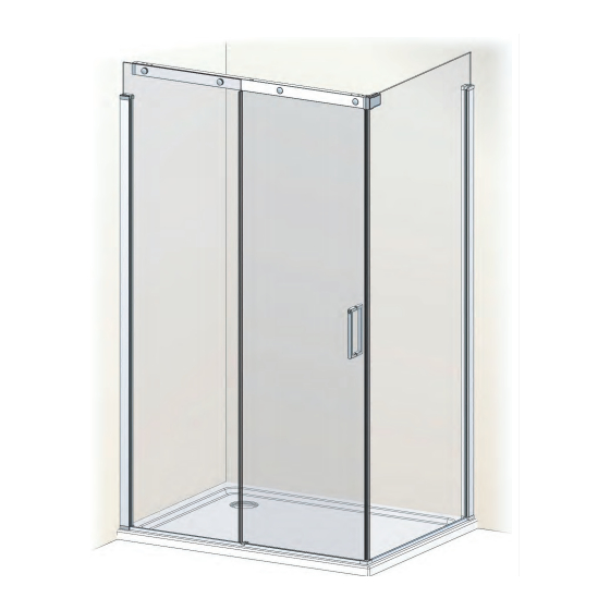
- Page 1 Island Sliding Door & Side Panel Installation & Maintenance Instructions 10.19 04.19...
- Page 2 We will resolve defects free of charge by repairing / replacing parts as we feel necessary. To be free of charge, service work must be carried out by Lakes Bathrooms or approved agents.
-
Page 3: Parts List
Parts List :- Side Panel & Island Sliding Door Trim Assembly (Seperate Boxed Product) Wall Pro le Wall Profile Cover Assembly Threshold Corner Kit Magnetic Seal Kit Corner Bracket Kit... -
Page 4: Tools Required
Tools Required :- Spirit level with vertical bubble Pencil Power drill & 8mm Pozidriv screwdriver masonry or tile bit Tape measure Allen keys (2.5, 3, & 5mm) Hacksaw Good quality silicone sealant and applicator Setting Out :- Door Size Adjustment (mm) 1000 970 - 995 1100... - Page 5 “X” Door Size Position “X” 1000 1100 1082 1200 1182 1300 1282 “Y” 1400 1382 1500 1482 1600 1582 1700 1682 1800 1782 1900 1882 2000 1982 To nd outside of wall pro le positions, Panel Size Position “Y” measure & mark “X” & “Y” for selected enclosure size. Using position “X”...
- Page 6 Lower threshold assembly onto tray and slide end trim under the side panel glass. Ensure threshold is parallel to front of tray and distance from front is equal along it’s complete length (10mm Min.) Fit xed panel into wall pro le and lower into threshold channel.
- Page 7 Assemble door to suit desired hand. Wheel assembly Door assembly for Door assembly for Handle assembly LEFT HAND enclosure. RIGHT HAND enclosure. Assemble horizontal rail to suit desired hand. Fixed Panel Spigot Kits Rail End Cap Blanking Kit Horizontal rail set up for RIGHT HAND door shown.
- Page 8 Assembly for Assembly for blanking kit. xed panel spigot. Use boss tment tool to hold boss in place during assembly Part assemble corner bracket as shown below to suit desired handing of enclosure. Assembly to suit RIGHT HAND door. Reverse and use opposite doorstop bu er for left hand.
- Page 9 Fix rail assembly to fixed panel glass using remaining parts of the spigot kits. Fix rail assembly to side panel glass using the remaining parts of the corner bracket. Ensure the horizontal rail is level then tighten the clamping screws on the wall profiles. There are 6 clamping screws per wall profile and all must be tightened to prevent glass movement in operation.
- Page 10 Fit profile caps to wall profiles. Remove screw in top of end trim, fit cap and replace screw to fix Push buffers onto fixed panel wall profile in 2 places. Select largest buffer into which door does NOT run when opened or closed.
- Page 11 Push magnetic seals onto edge of door glass and side panel. Seals may be wetted to ease fit. centre guide block (cut at this end of capping ONLY) threshold corner With drip lip to INSIDE, offer threshold capping upto threshold corner. Adjacent to centre guide block, measure / mark length required &...
- Page 12 Apply a continuous bead of clear silicone sealant as shown EXTERNALLY ONLY.
-
Page 13: Basic Troubleshooting
In the unlikely event of an enclosure leak water will be visible on the outside of the enclosure itself or around the perimeter joints only. Water appearing outside of the enclosure i.e. at oor level is normally due to incorrect tray installation. Lakes Bathrooms Ltd. Service - Northern Ireland Alexandra Way...
Need help?
Do you have a question about the LK861 and is the answer not in the manual?
Questions and answers