Table of Contents
Advertisement
Quick Links
Advertisement
Table of Contents

Related Manuals for Geoscan gemini


Summary of Contents for Geoscan gemini
- Page 1 User Manual...
-
Page 2: Table Of Contents
Contents Introduction Abbreviations List Main Information In The Box ........Service . - Page 3 Radiomodem Connecting ......UAV Connecting to Geoscan Planner ....
-
Page 4: Introduction
We always glad to help you and answer any questions. The information, specifications and pictures in this manual are relevant at the time of publication. Geoscan Group may change the UAV design or specifications without prior notice. Do not make any changes to the UAV structure by yourself. Any UAV damage or degraded specifications caused by structure changes are not covered by the warranty. -
Page 5: Abbreviations List
Abbreviations List GNSS — Global Navigation Satellite System OS — Operating system UAS — Unmanned Aerial System UAV — Unmanned Aerial Vehicle IMU — Inertial Measurement Unit... -
Page 6: Main Information
Main Information Geoscan Gemini unmanned aerial system is designed to perform aerial survey and produce the following spatial data: • 3D point cloud; • digital surface model; • digital terrain model; • ortophotomosaic map; • textured 3D polygon model. Fields of application: •... -
Page 7: In The Box
In The Box Geoscan Gemini UAV Flight Battery — 2 pcs. Battery Charger Propellers (pair) — 3 pcs. Radiomodem USB Type-C Cable SD Card 32 GB Documentation package Transport Case... -
Page 8: Service
Service After each flight visually inspect UAV for a damages. If propellers are damaged, you can replace them by using spare parts. If you detect any aircraft frame or system damages,contact our support for futher instructions. After the 160 hours total flight time we recommend you to send UAV to the manufacturer for a technical check and service. -
Page 9: Safety Rules
Safety Rules Following rules must be observed: • Only persons who have read this manual are allowed to use Geoscan Gemini UAS. • Do not short-circuit flight battery’s pins. • Do not launch UAV or calibrate magnetic compass near large metal objects and reinforced concrete structures (transmission towers, bridges, overpasses, etc.). -
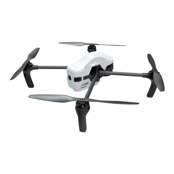
Page 10: Aircraft
Aircraft Aircraft Diagram 1. Sony UMC-R10С Digital Camera 5. Flight Battery 2. Precise Positioning Sensors 6. Electric Motors 3. SD Card Slot 7. Propellers 4. UAV Indicator 8. USB Type-C Port... -
Page 11: Key Features
Key Features This section contains a general description of Gemini’s systems. For more information please see Appendix section. Magnetic Compass Built-in magnetic compass allows accurately keep an orientation. GNSS Positioning Built-in high-precision GNSS receiver is supports dual frequency GPS/GLONASS L1/L2 tracking. GNSS tracking allows you to get the coordinates of the camera centers in PPK mode with an 1.5 cm accuracy even at a long distance from the GNSS base... -
Page 12: Internal And External Storage
Current arieal survey data will be automatically copied to the SD card after passing the last point of a flight task. Press Copy Data to SD button in Geoscan Planner software to copy data from previous flights. Please see Geoscan Planner Software section for more information. -
Page 13: Uav Indication
UAV Indication The Gemini has a LED indicator, which informs about the UAV status. The table describes LED indication: LED color Description Solution Glows solid red Critical error Contact support Flashes red Change or charge a flight battery Critical battery charge level Glows solid violet Magnetic сompass error... -
Page 14: Assembly
Assembly Propellers Attach propellers to the motor shafts. Pay attention that propellers and shafts are different in their directions of rotation. Propellers and shafts with the same rotation are marked with the same silver or black marks. Icons on the centers of propellers indicate the direction of rotation for their installation. Hold the motor’s rotor and screw every propeller on shaft with same mark. -
Page 15: Battery Installing And Ejecting
SD card after passing last point of flight task and will be saved on UAV internal storage only. Use Clear memory command in Geoscan Planner software to clean UAV internal memory. -
Page 16: Digital Camera
This features allow to take high-quality pictures even in low light conditions. Camera Settings Camera can be configured in Geoscan Planner software. UAV must be connected to the laptop. See Connection Settings section for more information. How to change camera settings in Geoscan Planner: •... - Page 17 Сamera settings The camera also can be used in manual mode (to set image quality, for example). Press Turn on or Turn off button to turn camera on or off. Take shot button allows to take photos manually. We recommend to use default quality settings in daylight conditions, but camera settings can be changed manually.
- Page 18 ISO — light sensitivity. A lower value leads to lower light sensitivity and less noise on photos. ISO can be set in the range from 100 to 3200. In the normal light conditions it is recommended to set the value to no more than 400. White balance —...
-
Page 19: Camera Rotation
Camera Rotation Geoscan Gemini allows to take not only planned survey, but also perspective shooting. In this case, the accuracy of 3D models are based on images will be much higher due to more accurate determination of object contours during photogrammetric processing. -
Page 20: Flight Battery
Flight Battery Flight Battery is designed for use with Geoscan Gemini UAV only. Flight Battery should be charged only by using a battery charger designed for Geoscan Gemini battery. Fully charge the battery before the first usage (see Charge mode section for details). -
Page 21: Battery Indication And Control
Holding buttons LEDs Control button Battery LEDs and buttons Battery Indication And Control Press the Control Button to turn the Flight Battery on. LED indicators will show the battery charge level. The battery LEDs are indicating charge level. Each turning on LED is a 25% of charge. Flashing LED is a 12,5% of charge. -
Page 22: Battery Charger
• Visually inspect charger slots and the power cable for damages before each use. Do not use damaged chargers or cables. • Do not leave turned on charger unattached. • The battery charger is designed for charging Gemini flight batteries only. -
Page 23: Parts And Operating Modes
Parts And Operating Modes Battery charger parts The battery charger can work in two operating modes: Charge and Storage. Charge mode allows to charge up to 2 flight batteries. If 2 batteries are installed, battery with a large charge level will start charge first. Storage mode allows to automatically charge or discharge batteries up to 60% of batteries capacity, that needed to store the batteries for 14 days or more. -
Page 24: Charge Mode
Charge Mode Follow these steps to charge batteries: • Connect the power cable to the battery charger. • Connect the battery charger to a power outlet (100 — 240 V, 50/60 Hz). • Switch the mode switcher in Charge position. •... -
Page 25: Firmware Update
Also you can copy the file and use it for update another Geoscan Gemini UAVs. Contact our technical support https:// www.geoscan.aero/ support... -
Page 26: Launch Area Requirements
Launch Area Requirements The launch area should have a diameter of 5 meters without any barriers and must be magnetic compatible. There should be no massive metal objects, power lines and other high- rise structures nearby that may affect GNSS signal. There must be no objects on the launch pad that could block the take- off and landing of UAV. -
Page 27: Geoscan Planner Software
Geoscan Planner Software Geoscan Planner software allows to configure UAV and create flight tasks for aerial survey of areas and single objects, Flight Task 1) Install and launch Geoscan Planner software. 2) Enter your login and password in authentication window. -
Page 29: Aerial Surveying
Aerial surveying Aerial surveying is a polygon surveying. User sets vertices of the polygon (more than 3) and the software will automatically calculates a flight route. 1) Press Create aerial surveying on the toolbar. Create aerial surveying 2) Click on the map to set vertexes of aerial survey area. The program will automatically calculate the flight route. -
Page 30: Change Flight Route Direction
1) right click on the vertex; 2) select Delete vertex. Delete vertex Change Flight Route Direction The need to change a flight route may be caused, if the force and direction of the wind are unfavorable (strong wind along the flight route of the polygon). Right-click on the polygon and select the option Optimization «Direction»... - Page 31 One of the vertices of the polygon will be colored gray. Use the point’s slider to set the flight route direction. Correction of the flight direction A new flight route through the polygon in a selected direction will be generated automatically.
-
Page 32: Start Point Changing
Start Point Changing To change the polygon entry point, follow these steps: 1) Select a polygon. Selected polygon 2) Select vertex, right click and choose Make start point here. Context menu of a point The selected point will be marked with a flag... -
Page 33: Linear Surveying
Linear Surveying Create linear surveying tool allows to create a flight route along linear objects, such as: rivers, roads, oil pipelines, etc. . 1) Press Create linear surveying button on the toolbar. Create linear surveying button 2) Single clicks to set a path around an object. The program will automatically generate flight route. -
Page 34: Flight By Points
Flight By Points Create flight by points tool can be used for inspection of territories and overflights of high-rise objects. 1) Press Create flight by points button on the toolbar. Create flight by points button 2) Single clicks to select flight route points. Flight by points By default, aerial survey is not performed during the flight by points. -
Page 35: Waiting Point
We recommend to set the waiting point with wind measurement before each flight element at the height of the flight element, especially if they are located a large distance from each other. Geoscan UAVs are not certified instruments of wind measurement. It cannot be used as a precise tool. -
Page 36: Landing Point
Waiting point in wind measure mode Landing Point Create landing point tool is used to set the UAV landing point. If there is no specified landing point, UAV will return to the starting point at the end of the flight task. 1) Press Create landing point button on the toolbar. -
Page 37: Connection Settings
The radio modem is used to load a flight task into the autopilot memory, set up and semi-automatic control the UAV flight up to 5 km using the Geoscan Planner software. This section describes how to set up wireless connection between the UAV and laptop. - Page 38 Adding a new device If UAV is not detected reconnect radiomodem by right-click on the MdmDisp icon and select Reconnect. in the context menu. If connection is failed: • Check connection of the radio modem to laptop’s USB socket. • Check network settings in NetTopology. •...
-
Page 39: Uav Connecting To Geoscan Planner
UAV Connecting To Geoscan Planner 1) Select Connect to the UAV — Search… in Flight tab. UAV connection 2) Select connection type in MdmDisp. Set IP-adress — localhost. In UAV list set UAV — Port 1. Connection settings The settings will be automatically saved. At the next connections turn on the UAV power and use Connect UAV button on the toolbar. -
Page 40: Magnetic Compass Calibration
Magnetic Compass Calibration Calibrate the UAV magnetic compass before flying over a new exploring area by select Flight — Service — Calibrate magnetic compass. Calibrate magnetic compass State on the thelemetry panel in Errors bar will change to Mag calib. The UAV LED indicator will lights yellow. -
Page 41: Start Preparing
Start Preparing Launch Start Preparing. Start preparing button Start preparing wizard window will be opened. Most checks are performed automatically. Follow instructions in the window. Start Preparing Wizard... - Page 42 Preparing stages: Initialization — Initialization of UAV systems. Flight mission — flight task checking and sending into UAV memory. Battery — battery life cycles, temperature and charge test. IMU check — inertial measurement units (gyroscope and accelerometer) check. Magnetic compass — magnetic compass check. UAV orientation —...
- Page 43 Errors description: • Flight task cannot be performed — change a flight task. • Battery is not fully charged — The flight may be performed, but be aware that the battery capacity may not be enough for a full-time flight. A fully charged battery can provide up to 40 minutes of flight time.
-
Page 44: Flight
Flight Press Start button to launch UAV. Start button Make sure that nothing is blocking propellers’ rotation and confirming the engines’ start. Starting engines approval Autopilot will check engines. Approve take-off confirmation window will be shown on the laptop screen. Approve the take-off. Start confirmation UAV will take off. -
Page 45: Cancel Tool
Cancel tool Cancel tool directs the UAV to starting point. After reaching the starting point, UAV will perform the landing. Press the Cancel button. Cancel button UAV will start flying to the starting point and and will land on it. Immediate Landing Immediate landing tool is used to perform immediate landing on the current flight point. -
Page 46: Guided Flight
Guided Flight Guided flight option sets a destination point on the map and height. UAV will reach the point and start point holding until flight confirmation or until the automatic return is triggered by the battery low charge. 1) Press Guided flight button. Guided flight button 2) Click a point on the map and set the flight height above the ground (Elevation). -
Page 47: Flight Without Using The Magnetic Compass
Flight Without Using The Magnetic Compass UAV can be used with turned magnetic compass off to avoid distortions of magnetic data (aerial survey in polar latitudes, metal structures near the flight route). Select Flight — Service — Turn off magnetic compass to turn magnetic compass off. -
Page 48: Semi-Automatic Control
Semi-automatic Control Activation of semi-automatic control mode is possible after UAV pre-flight check and take-off. Press Semi-automatic control button. Semi-automatic control button The UAV control will be switched to semi-automatic mode. In semi-automatic mode UAV will pause an areal flight task and If the semi-automatic mode is activated, UAV will pause an linear or aerial survey. -
Page 49: Launch
7) Press the battery control button once, again, and hold until all LEDs are lights first time ( 2 seconds), to turn UAV on and wait for system initialization. 8) Open a project in Geoscan Planner. Connect the UAV. Launch the Preparing wizard. Make sure that pre-launch check is successful. -
Page 50: Uav Disassembly
UAV Disassembly 1) Disable UAV in the same way as you turn it on (Press the battery control button once, again, and hold until all LEDs are lights first time). 2) Attach the lens cap to the camera lens. 3) Press battery instaling buttons and eject remove it from UAV battery slot. Always turn UAV off before removing the battery! 4) Hold the motor’s rotor and remove each propeller by rotating it in the opposite direction to what is indicated on the propeller’s icon.. -
Page 51: Appendix
Appendix Specifications Aircraft multirotor Aerial vehicle type Motors electric brushless motors, 4 PCs Weight (battery & propellers included) 1,9 kg Diagonal size (excluding propellers) 550 mm 40 min Max. flight time vertical: 5 m/s, horisontal: 15 m/s Max. flight speed Max. - Page 52 Sony UMC-R10C camera Max. resolution 5456 × 3632 (20.1 MP) Sensor size APS-C (23.2 × 15.4 mm) Shutter type mechanical, shutter speed, focal-plane Focal length 20 mm Max. aperture f/2,8 100 – 16000 ISO range Mechanical shutter speed 1/4000 – 30 sec Camera center offset (relative to the Х: 0 m Y: -0,0721 m Z: 0,0953 m phase center of the onboard GNSS...
- Page 53 Transport case Dimensions 638 × 505 × 224 mm Weight (including all parts of the 10 kg system) Protection class IP67 Wheeled...
Need help?
Do you have a question about the gemini and is the answer not in the manual?
Questions and answers