Table of Contents
Advertisement
Quick Links
Advertisement
Table of Contents

Subscribe to Our Youtube Channel
Related Manuals for Geoscan Lite


Summary of Contents for Geoscan Lite
- Page 1 Geoscan Lite User Manual Updated on September 24, 2021...
-
Page 2: Table Of Contents
Contents Introduction Abbreviations List Main Information Kit ..........Maintenance Service . - Page 3 Radio Modem Connection ......Connecting UAV to Geoscan Planner .....
- Page 4 Appendix Specifications ........
-
Page 5: Introduction
We always glad to help you and answer any questions. The information, specifications and pictures in this manual are relevant at the time of publication. Geoscan Group may change the UAV design or specifications without prior notice. Do not make any changes to UAV structure by yourself. Any UAV damages or de- graded specifications caused by structure changes are not covered by the warranty. -
Page 6: Abbreviations List
Abbreviations List GNSS Global Navigation Satellite System Unmanned Aerial Vehicle Universal Serial Bus... -
Page 7: Main Information
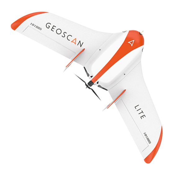
Main Information Geoscan Lite designed obtain georeferenced photos objects aerial photography. The aerial data can be used for: • terrain evaluaton; • aerial photography with precise time stamps for georeferenced images; • orthophotos and digital terrain mod- els creation; • altitude maps creation;... -
Page 8: Kit
• Geoscan Lite UAV • UAV Transport Bag/Protective Case • Launcher in Transport Bag • Customized Camera • Battery • Radio Modem with Antenna • Battery Charger • Geoscan Planner Software • Folding Rack • Spare parts and accessories... -
Page 9: Maintenance Service
After 80 flights it is recommended to send your UAV to the manufacturer for inspection and maintenance. Storage Geoscan Lite system (without battery) and launcher are recommended to be stored in transport bags and dry room at a temperature of +5 to +25 °C and relative humidity not more than 80% without any condensation. -
Page 10: Safety Rules
You should follow these rules for safe UAV using: • UAV launch and maintainence can be held only by persons, who trained for Geoscan Lite unmanned aerial system operation and read this manual. • Follow the dealer’s and/or manufacturer’s recommendations and instructions for use of the equipment, as given in this manual and received during operation period. - Page 11 Follow these operating precautions: • Do not assemble or disassemble the UAV when the power is on; • Do not stay near the propeller when the power is on; • Installation and removal of the propeller’s blades is allowed only when the power UAV turned off;...
-
Page 12: Assembly
Assembly UAV Assembly 1.Take the Wings and Fuselage from the UAV transport bag. 2. Place the Parachute in the parachute compartment (see Parachute section for de- tails). 3. Remove Fuselage Top Cover: unclasp the rubber locks to unlock the cover; Eject back of the cover from grooves. - Page 13 4. Insert Mounting Rod into the Fuselage Tube. Mounting Rod inserting 5. Put the Wings on Mounting Rods and move them to fuselage. Wing installing...
- Page 14 6. Attach Fins and fix them in place. Make sure the Fins are secured by magnets. Installation of the fins 7. Connect wings’ cable connectors into the appropriate slots in the autopilot. Connect GNSS reciever cable, if UAV delivery kit included this option. Cables connection...
- Page 15 8. Remove memory cards from autopilot and camera. Format them and put back in slots. 9. Place and lock the Battery by textile clasp. 10. Connect power connector with the battery. SD card and Battery instaling. The Battery connection. 11. Set up the Camera (see Camera Settings section for details) Place Camera in UAV cradle.
- Page 16 12. Close the top cover and clasp the rubber locks. Fuselage Top Cover closing UAV is ready for pre-launch check.
-
Page 17: Parachute
Parachute Parachute components: 1. Parachute Compartment Cover 5. Locking Ring 2. Parachute Dome 6. Long Static Line 3. Rigging Lines’ Pockets; 7. Short static line with unhook ring system 4. Rigging Lines... -
Page 18: Parachute Folding
Parachute Folding Make sure that the Parachute Dome, Rigging Lines and their attachment to the dome are not damaged before laying the Parachute. The Dome and Rigging Lines should be dry and clean. Repack the Parachute if the previous packaging is more than 10 days ago, or you were carrying UAV in an airplane. - Page 19 4. Fold the Dome in half and align the edges. Folding the Dome in half second time As the result, the Rigging Lines should be collected in 4 bundles with 4 rigging lines in each. Result...
- Page 20 5. Fold the Dome in half again. The pockets for laying the rigging lines must be outside. Folding Rigging Lines pockets out 6. Fold the Dome as see on the picture. Folding the Dome Make sure that in the process of laying the parachute rigging lines are not tangled. Straighten the lines out if it needs.
- Page 21 7. Put the Rigging Lines in the pocket. Measure the length of the bundle of rigging lines exceeding the depth of the pocket. Fold the rigging lines bundle in half and stretch in the pocket, so that the bend of the bundle a few centimeters protruded from the opposite side of the pocket.
- Page 22 Result 9. Fold the Dome as see a picture. Dome folding...
-
Page 23: Parachute Installing
Parachute Installing 1. Turn the UAV to The Parachute Compartment was on top. 2. Pick up the Carabiner and straight the Rigging Lines. 3. Put the short static line end in a carabiner (see a picture). Short static line end in carabiner 4. - Page 24 Short static line end turning into the ring of deattaching system 5. Put short static line end in deattach system ring and lock the rope between halfs of locker. Locking the loop in the lock Make sure that deattach system lock is securely locked.
- Page 25 6. Make sure that deattach system lock is securely locked: take the parachute dome and make some short sharp jerks. Deattach lock check 7. Carrfully pack the ropes of parachute system and rigging lines. 8. Pack the folded parachute. The base of the parachute with the ring was at the bottom of the parachute compartment.
- Page 26 9. Put the salient in parachute compartment’s cover rear in UAV body’s slot and hold down the cover. Lock the cover by servo horn. Check that the parashute compartment cover can opens. To do that just rotate servo horn. The parashute rigging lines must be free. 10.
-
Page 27: Launcher
Launcher Parts... -
Page 28: Assembly
Assembly 1. Take out the launcher parts from transport bag. 2. Spread out the supports on the launcher front part. Make sure that they are se- curely fastened by locks. To fold the supports pull the locks down. Supports installing 3. - Page 29 4. Attach the launcher’s rear part. Attaching of the launcher’s rear part 5. Insert the locking pin into the hole in the launcher’s middle and rear part. 6. Place the launcher on a flat surface. The UAV must be launched against the wind. Make sure that the launcher is stable on the ground and that its guide has no roll.
- Page 30 7. Install and hammer the stop peg into the hole at the rear part of the launcher to prevent displacements when the UAV starts. The jerk of the rubber cords leads to the throwing of the launcher’s rear part, when the UAV starting. You must hammer on the stop peg on the entire length to fix the launcher’s rear part.
- Page 31 9. Move the carriage down until it locks in the lock. 10. Insert the safety pin into the starting mechanism. Inserting the safety pin The lock may accidentally trigger, if you does not insert the pin! 11. Eject winch stopping pin and unwind the tension cable.
- Page 32 12. Take the rubber cords. Straighten the cords. Make sure the cords are not tangled. 13. Use the rope ring at the end of the rubber cord to make loop and hook the carriage. Rope ring loop 14. Connect the another end of the rubber cord to the end of the starting cable by a carabiner.
-
Page 33: Preparation To Uav Launch
Preparation to UAV Launch Pull the cords only after the successful pre-launch preparation immedi- ately before the launch. This will increase their shelf life and ensure safety on the launch area. 1. Move the winch stopper to the cable tension position. 2. -
Page 34: Camera Settings
Camera Settings UAV сamera type depends on delivery kit. This section describe recommended set- tings for aerial survey in normal daylight conditions. Sony DSC-RX1RM2 Digital Camera Main Parts Please, carfully read Camera Operating instructions https:// www.sony.com/ electronics/ support/ res/ manuals/ 4579/ 45798651M.pdf to get full information about functions and control parts before change settings. -
Page 35: Presets
Presets Geoscan UAVs are equipped with 2 presets for Sony DSC-RX1RM2 cameras. Use Mode Dial near ON\OFF switcher to select preset for your needs. Preset 1 serves for shooting in normal daylight conditions. The aperture value is fixed, which provides fixed aperture for better ortophotomosaic generation. -
Page 36: Presets Restoring
Presets Restoring Settings of 1 and 2 presets can be restored, if you change them. For preset 1 restoring: • Set Mode Dial in position M (Manual aperture control). • Set shutter speed 1/1000 by Control Dial. • Select ISO — Auto in camera menu.. Press Menu button, go to Camera Settings (Tab 8) and select Memory. -
Page 37: Sd Card Formating
• In settings section set Power Saving Start Time — 30 min. (tab 2) и File Number — Reset (tab 5). Power saving start time File number reset SD Card Formating • In Settings menu (tab 5) select Format. Format option All data on SD card will be deleted! -
Page 38: Settings Reset
Settings Reset Reset of the camera will delete presets’ shooting settings (Presets 1 and 2)! • In Settings menu (tab 6) select Setting Reset «Setting reset» option Do not remove the battery during a reset process! • After camera reboot, you need to set Timezone and date, otherwise the settings will not be saved and this menu will appear at every turn on. -
Page 39: Sony Dsc-Rx1 Digital Camera
Sony DSC-RX1 Digital Camera Main Parts Please, carfully read Camera Operating Instructions https:// www.sony.ru/ electronics/ support/ res/ manuals/ 4469/ 44695786M.pdf to get full information about functions and control parts before change settings. Basic camera control elements are shown on the picture: 1. - Page 40 To set camera soft parameters, push MENU button, then select parameters according to the following instructions. • In User settings menu (tab 1) turn off Automatic preview and set MOVIE Button — Movie mode only (tab 3). Turn off automatic preview Movie mode only •...
-
Page 41: Sd Card Formating
SD Card Formating • Select MENU [Memory card] Format All memory card data will be deleted! Settings Reset Follow these steps to set default settings: • Select MENU [Settings menu] INITIALISATION Reset Do not remove the battery during a reset process! •... -
Page 42: Sony A6000 Digital Camera
Sony A6000 Digital Camera Main Parts Please, carfully read Camera Operating Instructions https:// www.sony.ru/ electronics/ support/ res/ manuals/ 4532/ 45320554M.pdf to get full information about functions and control parts before change settings. Basic camera control elements are shown on the picture: AVCHD MENU 24.3 MEGAPIXELS... -
Page 43: Sd Card Formating
• In Custom Settings menu (tab 1) disable Automatic preview, turn on Lens-less Shut- ter (tab 3) and set MOVIE button - Video mode only (tab 6). Automatic preview off Turn on the shutter without a lens Video mode only for Movie button •... -
Page 44: Offsets
Offsets The information is valid for Geoscan Lite UAVs with GNSS-receiver Topcon B111. The antenna of the geodetic receiver is located inside the UAV wing. The phase center is offset from the center point of the camera lens. The offsets coor- dinates should be taken, when you generate ortophotomaps and 3D models. -
Page 45: Charger And Battery
Charger and Battery The section contains presets for chargers’ , that can be included with UAV and rules for safe battery using. Safety Rules Battery • Do not disassemble or deform the battery (don’t drop and pierce). • Do not allow heat the battery more than +60 degrees. •... -
Page 46: Tips For Lithium Polymer (Lipo) Battery Using
Tips for Lithium Polymer (LiPo) Battery Using The following rules must be observed to prevent dangerous situations: • The battery must be stored in a warm place before launch for a flights in a temperature lower than 0 °C. LiPo batteries can lose up to 30% of a capacity in cold. -
Page 47: Skyrc 6X80+ Battery Charger
SkyRC 6X80+ Battery Charger 60X80+ PUSH ENTER START S KYRC Mode/Stop SkyRC 6X80+ Battery Charger Choose and change settings by control wheel on the front panel. Mode/Stop button provides cells type select and stop charging process. Charge Settings 1. Connect AC cable. 2. -
Page 48: Skyrc T6755 Battery Charger
SkyRC T6755 Battery Charger SkyRC T6755 Battery Charger Use the touch screen to set charge parameters. Charge Settings Select LiPo in Batt Type section. Select Charge in Operation section. LiPo and Charge settings Set 4S in Cells menu. Cells menu... -
Page 49: Battery Charging
In Capacity menu set: Capacity — 11300 mAh; Charge Current — 6.0 A; Discharge Current — 2.0 A. Capacity menu settings In Safety Protection section of Setting menu select: Capacity Cut Off - 11300 mAh. Safety Time Off - 200 min. Temp. -
Page 50: Imaxrc X100 Battery Charger
ImaxRC X100 Battery Charger ImaxRC X100 Battery Charger Use the touch screen to set charge settings. Modes and Settings Select LiPo in Type section and 4Cells. Select 14.8V in Cells section and press Ok button. Type selection Cells section Select mode in Mode section: Balance - for battery cells balancing;... - Page 51 Select charge current (top slider) 6.0A, discharge current (bottom slider) in Current section and press ОK button. Current Select Uset section: Settings Select Cut-off Time — 200 Minute and press OK button. Select Cut-off Capacity —10.0 Ah and press ОK button. Cut-off Time Cut-off Capacity...
-
Page 52: Battery Charging
Battery Charging 1. Connect AC power cable. 2. Put AC plug in a socket. 3. Connect balance cable to the battery. 4. Connect power cable to the battery. 5. Check settings and press Start button to start charge process. Start button 6. -
Page 53: Storage And Discharge
Storage and Discharge Use storage mode for a long (more than 14 days) battery storage. Switch the charger to Storage mode, check battery cells (4 Cells (4S)) and start storage cells balancing by press Start button. Store batteries in dry cool place without direct sun light at the temperature range from +5 to +25 °С... -
Page 54: Geoscan Planner Software
Geoscan Planner Software Geoscan Planner software allows to configure UAV and create flight tasks for aerial survey of areas and single objects. System Requirements Minimum System Requirements Operating system MS Windows 7,8,10 Intel Core i3 4 Gb GPU Type Dedicated... -
Page 55: New Project
New Project 1. Install and launch Geoscan Planner software. 2. Enter your login/password in authentication window and create new project by press New Project button. Authentication window New Project button 3. Enter a project name and shooting parameters in the new project window. -
Page 56: Aerial Surveying
Aerial Surveying Aerial surveying is a polygon surveying. User sets vertices of the polygon (more than 3) and the software will automatically calculates a flight route. 1. Press Create aerial surveying on the toolbar. Create aerial surveying 2. Click on the map to set vertexes of aerial survey area. The program will automati- cally calculate the flight route. - Page 57 To remove the vertex: 1. Right click on the vertex. 2. Select Delete vertex. Delete vertex Change Flight Route Direction The need to change a flight route may be caused, if the force and direction of the wind are unfavorable (strong wind along the flight route of the polygon). Right-click on the polygon and select the option Optimization «Direction»...
- Page 58 One of the vertices of the polygon will be colored gray. Use the point’s slider to set the flight route direction. Correction of the flight direction A new flight route through the polygon in a selected direction will be generated au- tomatically.
- Page 59 Start Point Changing Follow these steps to change the polygon entry point: 1. Select a polygon. Selected polygon 2. Select vertex, right click and choose Make start point here. Context menu of a point The selected point will be marked with a flag...
-
Page 60: Linear Surveying
Linear Surveying Create linear surveying tool allows to create a flight route along linear objects, such as: rivers, roads, oil pipelines, etc. . 1. Press Create linear surveying button on the toolbar. Create linear surveying button 2. Single clicks to set a path around an object. The program will automatically gen- erate flight route. -
Page 61: Hop
Fight by pre-seted route with a seted altitude. It is mainly used for passing around point objects (i.e. high objects) and topographic inequality. Click on the icon Create hop on the toolbar. Create hop button 2. Specify the flight route by single- clicking. -
Page 62: Waiting Point
Waiting Point Create waiting point tool allows to hold UAV on selected map point. 1. Press Create waiting point on the toolbar. Waiting point button 2. Click mouse button on the map to set waiting point. You can activate more options an expert mode: set delay point height, waiting time, direction, wind measurement and endless devay functions. - Page 63 Infinite waiting option sets holding point in the air (point will be hold until the low battery charge will trigger automatic return to start point). The waiting point color will change to deep blue. Infinite waiting point We recommend to set the waiting point with wind measurement before each flight element at the height of the flight element, especially if they are located a large distance from each other.
-
Page 64: Landing Point
Landing Point Create landing point tool is used to set the UAV landing point. It is necessary to land UAV at the flight mission end. Choose open dry place without trees and other barriers for landing. Check the wing direction at landing route and correct land trajectory if it needs. 1. -
Page 65: Connection Settings
Connection Settings Radio Modem Connection The radio modem is used to load a flight task into the autopilot memory, set up and semi-automatic control UAV flight up to 40 km, if a flight zone doesn’t have any signal barriers. This section describes how to set up wireless connection between the UAV and laptop. - Page 66 Adding a new device If UAV is not detected reconnect radio modem by right-click on the MdmDisp icon and select Reconnect. in the context menu. If connection is failed: • Check connection of the radio modem to laptop’s USB socket. •...
-
Page 67: Connecting Uav To Geoscan Planner
Connecting UAV to Geoscan Planner 1) Select Connect to the UAV — Search… in Flight tab. UAV connection 2) Select connection type in MdmDisp. Set IP-adress — localhost. In UAV list set UAV — Port 1. Connection settings The settings will be automatically saved. At the next connections turn on the UAV power and use Connect UAV button on the toolbar. -
Page 68: Pre-Launch Check
Pre-launch Check Launch Start Preparing Wizard. Start Preparing Wizard launch button Follow the instructions of the Start preparing Wizard (most tests are runned automatically). On Parameters stage set: Parashute autodeatach radius (m) — radius around landing point, that trigged parashute autodeattach after landing. -
Page 69: Flight
Flight Press Start button. Start button UAV autopilot will change mode to start. The telemetry panel will display CATAPULT mode. Catapult mode It is necessary to switch the UAV to start mode only after placing it on the launcher. It is forbidden to take and move the UAV after switching to CATAPULT mode. -
Page 70: Launch
Launch Follow the instructions, to launch GEOSCAN Lite: 1. Charge the battery and make sure it works correctly (see Battery Charger section for details). 2. Create a flight task (see Geoscan Planner Software section for details). Don’t forget to set the landing point. - Page 71 12. Press Start button to switch UAV autopilot in catapult mode. Remove safety lock and pull the launching cord to launch the UAV. The UAV will take off. 13. Loose the tension of the rubber cords after starting the UAV. Hold the winch handle with one hand, and the second - remove the winch stopper and smoothly unwind the tension cable.
-
Page 72: Uav Disassembly
UAV Disassembly 1. Unclasp rubber locks to remove fuselage’s top cover. Remove the back of the cover from grooves. 2. Turn UAV power off. SD card can be removed from UAV camera to process a shooting results. 3. Close fuselage’s top cover by inserting the back of the cover into grooves and clasp rubber locks. - Page 73 Appendix Specifications Fixed-wing UAV Type Electric Brushless Motor 64 - 130 km/h Flight Speed 3,1 kg Max. Weight 0,8 kg Max. Payload Weight 12 m/s Max. Wind Resistance 1,38 cm Wingspan 100 m Min. Safety Flight Altitude 4000 m Max. Flight Altitude (ASL) 60 min Max.
- Page 74 Battery LiPo Battery Type 11300 mA·h Capacity Cells Recommended Current: 6 A Charge Current Max. Current: 10 A 16,8 V Max. Charge Voltage 13,2 V Min. Charge Voltage 14,8 V Normal Voltage from -20 to +40°С Operating Temperature Range Dimensions 165 ×...
- Page 75 Sony DSC-RX1RM2 Digital Camera * Sensor Full-frame CMOS Exmor R (35.9x24 mm) Number of Pixels 43,6 MP Shutter central Aperture f/2-22 ISO Range 100-102400 Shutter Speed from 1/4000 to 30 sec Sony A6000 Digital Camera * Sensor CMOS Number of Pixels 24,3 MP Shutter focal...
- Page 76 Geoscan Group, 2021...
Need help?
Do you have a question about the Lite and is the answer not in the manual?
Questions and answers