Table of Contents
Advertisement
Quick Links
Advertisement
Table of Contents

Related Manuals for ABB SCC-F


Summary of Contents for ABB SCC-F
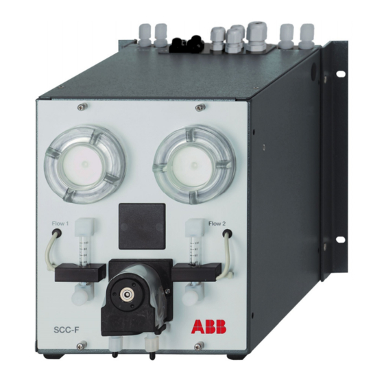
- Page 1 SCC-F Sample gas feed unit Operator’s manual 42/23-51 EN Rev. 3...
-
Page 2: Table Of Contents
Installing the sample gas feed unit and sample gas cooler side-by-side Connecting the electrical leads: Notes Connecting the electrical leads: SCC-F without I/O card Connecting the electrical leads: SCC-F with I/O card Setting up the I/O card in the gas analyzer ... -
Page 3: Preface
This operator’s manual contains all the information you will need to safely and operator’s manual efficiently install, start-up, operate and maintain the SCC-F sample gas feed unit. This operator’s manual contains information on all the functional units in the sample gas feed unit. The delivered sample gas feed unit may differ from the version described. -
Page 4: Safety Information
Safety information Intended application, instrument designs Intended application The SCC-F sample gas feed unit is designed for continuous dosed feeding of sample gas. The SCC-F sample gas feed unit must not be used for feeding mixtures of gas/air or gas /oxygen that are capable of ignition during normal service, ... -
Page 5: General Safety Information
Failure to do so can put persons at risk and can lead to unit damage as well as damage to other systems and instruments. 42/23-51 EN Rev. 3 SCC-F Sample gas feed unit Operator’s manual... -
Page 6: Safety Tips For Handling Electronic Measurement Devices
EXPLOSION HAZARD Do not disconnect equipment unless power has been switched off or the area is known to be non-hazardous. I/O connectors must only be connected to Class 2 circuits. SCC-F Sample gas feed unit Operator’s manual 42/23-51 EN Rev. 3... -
Page 7: Preparing The Installation
In operation: +5 to +45 °C Storage and transport: –25 to +60 °C 75 % year-round average, 95 % on 30 days per year, Relative humidity occasional light condensation permissible 42/23-51 EN Rev. 3 SCC-F Sample gas feed unit Operator’s manual... -
Page 8: Power Supply
(for the cables to /from the SCC-C sample gas cooler) Power supply connection cable, 3-conductor, length approx. 50 cm Connection cable, 2-conductor, length approx. 40 cm The fixing brackets are fitted in the factory. SCC-F Sample gas feed unit Operator’s manual 42/23-51 EN Rev. 3... -
Page 9: Installation And Start-Up
The user is responsible for the secure mounting of the unit. Figure 1 shows options. The scope and features of the ordered version may differ. Continued on next page 42/23-51 EN Rev. 3 SCC-F Sample gas feed unit Operator’s manual... - Page 10 Use a Ph2 crosshead screwdriver to loosen the two M6x25 screws in restraints the base plate. Retain the screws in case the unit needs to be transported again in the future. SCC-F Sample gas feed unit Operator’s manual 42/23-51 EN Rev. 3...
- Page 11 Installing the sample The best way to install the SCC-F feed unit and the SCC-C cooler unit in a 19-inch gas feed unit and cabinet or a 19-inch rack is side-by-side. In this case, the sample gas feed unit sample gas cooler should be installed on the left and the cooler unit on the right (see Figure 2).
- Page 12 Make sure that the casings are aligned precisely relative to one another, then tighten all 4 screws. Insert the rubber bushing in the hole 5. Continued on next page SCC-F Sample gas feed unit Operator’s manual 42/23-51 EN Rev. 3...
- Page 13 Connect the signal, control and power supply leads. side-by-side SCC-F without I/O card: see instructions on page 15, SCC-F with I/O card: see instructions on page 18. (continued) Close casings of sample gas feed unit and sample gas cooler: Replace and secure the sample gas cooler’s covering hood as well as...
-
Page 14: Connecting The Electrical Leads: Notes
2 switch off diaphragm pump 2 Connection of the If the SCC-F sample gas feed unit and the SCC-C sample gas cooler are used sample gas cooler together (e.g. in an analysis system), the electrical leads from the sample gas... -
Page 15: Connecting The Electrical Leads: Scc-F Without I/O Card
Connecting the electrical leads: SCC-F without I/O card Connecting the Step Action electrical leads Connect signal and control leads to the sample gas feed unit: Connect the status signal leads of the condensate and flow monitoring (see Figures 3, 4 and 5) to terminal strip X3. - Page 16 Connecting the electrical leads: SCC-F without I/O card, continued Figure 3 SCC-F Connection diagram: Sample gas feed unit Liquid Alarm 1 without I/O card Liquid Alarm 2 Flow Alarm 1 Flow Alarm 2 External Control Diaphragm Pump 1 External Control...
- Page 17 Connecting the electrical leads: SCC-F without I/O card, continued Figure 4 Terminal strip positions in the sample gas feed unit without I/O card 115V 115V 2 A T 230V 230V F2 50 mA T 10 9 8 7 6 5 4 3 2 1...
-
Page 18: Connecting The Electrical Leads: Scc-F With I/O Card
Connecting the electrical leads: SCC-F with I/O card Connecting the Step Action electrical leads Connect signal and control leads to the sample gas feed unit: Connect the status signal leads of the external devices (e.g. conden- (see Figures 5, 6 and 7) sate collecting bottle, reagent supply bottle) to terminal strips X10 (digital inputs DI1 –... - Page 19 Connecting the electrical leads: SCC-F with I/O card, continued Connecting the Step Action electrical leads Connect the power supply to the sample gas feed unit: Make sure the voltage setting shown on the rating plate matches (continued) the line voltage.
- Page 20 Connecting the electrical leads: SCC-F with I/O card, continued Figure 6 SCC-F Connection diagram: Standard assignment: Sample gas feed unit Reagent bottle 1 to 24 V DC with I/O card Level too low Reagent bottle 2 to 24 V DC...
- Page 21 Connecting the electrical leads: SCC-F with I/O card, continued Figure 7 Terminal strip posi- tions on the I/O card in the sample gas feed unit X1 Power supply input X2 Ground X3 Power supply output (to SCC-C sample gas cooler)
-
Page 22: Setting Up The I/O Card In The Gas Analyzer
Connect the sample gas pipes to the sample gas inlets and outlets. The sample sample gas pipes gas pipes should be made from material that is suited to the measuring task. Observe the sample gas inlet conditions (see page 8)! SCC-F Sample gas feed unit Operator’s manual 42/23-51 EN Rev. 3... -
Page 23: Power Supply Activation, Lead Time
Set sample gas flow Set the sample gas flow using the appropriate needle valve. CAUTION! The needle valves must never be closed completely. 42/23-51 EN Rev. 3 SCC-F Sample gas feed unit Operator’s manual... -
Page 24: Maintenance
Press the pressure rollers 5 together and check the spring pressure; if it is too weak, then the pressure springs and possibly rollers should be replaced (see page 26). Continued on next page SCC-F Sample gas feed unit Operator’s manual 42/23-51 EN Rev. 3... - Page 25 The sample gas flow should only be restarted after the lead time period. Figure 8 Dosing pump, hose and pump head with roller mounting 1 Moving belt 3 Hose 5 Pressure rollers 2 S-clip 4 Hose connections 6 Dovetail guides 42/23-51 EN Rev. 3 SCC-F Sample gas feed unit Operator’s manual...
-
Page 26: Replacing The Dosing Pump Pressure Rollers And Springs
Start the sample gas feed unit again: Switch on power supply to sample gas feed unit. The sample gas flow should only be restarted after the lead time period. Continued on next page SCC-F Sample gas feed unit Operator’s manual 42/23-51 EN Rev. 3... - Page 27 5 Roller mounting 2 S-clip 6 Pressure springs (x 4) 3 Nuts for securing the pump head (x 2) 7 Roller axle 4 Pump head 8 Pressure roller (x 2) 42/23-51 EN Rev. 3 SCC-F Sample gas feed unit Operator’s manual...
-
Page 28: Replacing The Diaphragm And Valve Plates In The Diaphragm Pump
Head cap Casing Counter weight Head cap screws Connecting rod 10 Eccentric Spacer plate Valve plates 11 Belleville spring Structural diaphragm Sealing rings 12 Distance ring(s) Continued on next page SCC-F Sample gas feed unit Operator’s manual 42/23-51 EN Rev. 3... - Page 29 Move the connecting rod 6 to its upper return point. Screw the new structural diaphragm with distance ring(s) and Belleville spring in a clockwise direction onto the connecting rod and hand- tighten it. Continued on next page 42/23-51 EN Rev. 3 SCC-F Sample gas feed unit Operator’s manual...
- Page 30 Check that the gas paths have no leaks (see instructions on page 31). Switch on power supply to feed unit. The sample gas flow should only be restarted after the lead time period. SCC-F Sample gas feed unit Operator’s manual 42/23-51 EN Rev. 3...
-
Page 31: Checking The Gas Paths For Leaks
Remove blockage or open modules. blocked or sealed off Negative pressure on the Rectify negative pressure. gas sampling side Positive pressure in the Rectify positive pressure. waste gas pipe 42/23-51 EN Rev. 3 SCC-F Sample gas feed unit Operator’s manual... -
Page 32: Shutting Down And Packing
Make sure the sample gas feed unit is free of residual moisture that can freeze if low temperatures are encountered during shipping and storage. Ambient temperature for storage and transportation: –25 to +60 °C SCC-F Sample gas feed unit Operator’s manual 42/23-51 EN Rev. 3... -
Page 33: Packing The Sample Gas Feed Unit
When shipping overseas the box should also be lined with a layer of protective waterproof wrapping. Mark the box “Fragile item” and “Transport upright”. Ambient temperature Ambient temperature for storage and transportation: –25 to +60 °C 42/23-51 EN Rev. 3 SCC-F Sample gas feed unit Operator’s manual... -
Page 34: Use And Functions Of The Sample Gas Feed Unit
Use and functions of the sample gas feed unit The purpose of using The SCC-F sample gas feed unit forms part of the sample gas conditioning system the sample gas feed in an analysis system. It is designed for continuous dosed feeding of sample gas. -
Page 35: Description
Description Design The SCC-F sample gas feed unit is produced in a 1/2 19-inch casing. It contains: One or two diaphragm pumps for feeding the sample gas, One or two flow monitors with needle valves, One or two condensate monitors, ... -
Page 36: Pneumatic Diagrams
23212-0-12xxxx000000 Figure 14 1 gas feed path with 1 condensate monitor, 1 diaphragm pump Version Catalog No. 2 flow monitors 23212-0-13xxxx000000 (e.g. for NOx measurement) Continued on next page SCC-F Sample gas feed unit Operator’s manual 42/23-51 EN Rev. 3... - Page 37 1 condensate monitor each, 1 flow monitor in Version Catalog No. first gas feed path and 1 diaphragm pump in 23212-0-16xxxx000000 second gas feed path (e.g. for SO measurement in separate gas feed path with AO2000-Limas11) 42/23-51 EN Rev. 3 SCC-F Sample gas feed unit Operator’s manual...
-
Page 38: I/O Card
I/O card I/O card option An I/O card is installed in the SCC-F sample gas feed unit as an option. The SCC-F sample gas feed unit and the SCC-C sample gas cooler are connected to the AO2000 gas analyzers via the I/O card and the system bus (see Figure 18). -
Page 39: Operating Specifications
Lead time Approx. 10 min. (plus cooler lead time) Dead volume Approx. 10 cm (plus dead volume of heat exchanger) Gas seal integrity 5 x 10 –6 hPa l/s 42/23-51 EN Rev. 3 SCC-F Sample gas feed unit Operator’s manual... -
Page 40: Index
Replace pressure rollers and springs Standard model Status signals Gas connections Gas pipe connection Transportation restraints 10, 13, 33 Troubleshooting I/O card Connecting the electrical leads Version for Class I, Div. 2 SCC-F Sample gas feed unit Operator’s manual 42/23-51 EN Rev. 3... - Page 42 ABB has Sales & Customer Support expertise The Company’s policy is one of continuous product in over 100 countries worldwide. improvement and the right is reserved to modify the information contained herein without notice. www.abb.com Printed in the Fed. Rep. of Germany (04.15) ...
Need help?
Do you have a question about the SCC-F and is the answer not in the manual?
Questions and answers