Table of Contents
Advertisement
Quick Links
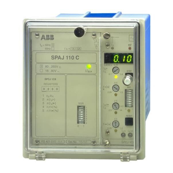
SPAJ 110 C
Earth-fault relay
User´s manual and Technical description
I
f
= 1A
n = 50Hz
5A (
I
)
n
SPAJ 110 C
80...265V ~ –
18...80V –
SPCJ 1C8
REGISTERS
0 0 0 0
1
I
/
I
o
n
2
n
(
>
)
I
o
3
(
> >
)
n
I
o
4
>
[
]
t
t
%
/
5
[
]
t
t
> >
%
/
RS 421
Ser.No.
B
2
I
o
5
60Hz
STEP
0.35
I o
>
U
aux
I
n
0.1
t
[ ]
>
s
k
0.05
SGR
I o
>>
I
1
n
2
0.5
3
4
5
6
7
8
t
[ ]
>>
s
0
1
0.05
I
IRF
STEP
0.8
0.5
SG1
1
1.0
2
3
4
5
2.5
6
7
8
4.0
0
1
RESET
0.5
1.0
I o
I o
>
>>
SPCJ 1C8
Advertisement
Chapters
Table of Contents

Related Manuals for ABB SPAJ 110 C


Summary of Contents for ABB SPAJ 110 C
- Page 1 SPAJ 110 C Earth-fault relay User´s manual and Technical description = 1A n = 50Hz 5A ( 60Hz SPAJ 110 C STEP 0.35 80...265V ~ – > 18...80V – STEP SPCJ 1C8 REGISTERS > 0 0 0 0 0.05 >...
-
Page 2: Table Of Contents
Ordering numbers ......................18 Dimensions and instructions for mounting ..............19 Order information ......................19 The complete manual for the earth-fault relay SPAJ 110 C includes the following partial manuals: Earth-fault relay SPAJ 110 C, general part 1MRS 750801-MUM EN... -
Page 3: Description Of Operation
START 2 PROTECTION STAGE OR BOTH SERIAL COMMUNICATION PORT SERIAL I/O BLOCKING Fig. 1. Protection functions of the earth-fault relay SPAJ 110 C. The encircled numbers refer to the ANSI (=American National Standards Institute) number of the concerned protection function. -
Page 4: Connections
≅ SGR/1 t >,k Io> t >> Io>> SPAJ 110 C Fig. 2. Connection diagram for the earth-fault relay SPAJ 110 C. Auxiliary voltage A, B, C, D, E, F Output relays Self-supervision function Blocking signal Start signal Trip signal... - Page 5 Fig.3. Rear view of earth-fault relay SPAJ 110 C. Specification of input and output terminals Contacts Function 25-26 Neutral current I = 5 A) 25-27 Neutral current I = 1 A) 10-11 External blocking signal (BS) 61-62 Auxiliary power supply.
-
Page 6: Configuration Of Output Relays
The start signal of the I > stage is firmly/solidly following functions can be selected with the Configuration of wired to output relay F and the trip signal to switches of the SGR switchgroup on the front output relays output relay A. The trip signal of the I >>... -
Page 7: Start And Operation Indicators
I is currently indicators = 1A 5A ( n = 50Hz 60Hz being displayed. SPAJ 110 C 3. The red IRF indicator of the self-supervision STEP 0.35 80...265V ~ – > system indicates, when lit, that a permanent 18...80V –... -
Page 8: Technical Data
Technical data Energizing inputs Terminals 25-27 25-26 Rated current I Thermal withstand capability Carry continuously 20 A Make and carry for 10 s 25 A 100 A Make and carry for 1 s 100 A 500 A Dynamic current withstand capability, half-wave value 250 A 1250 A... - Page 9 Non-directional earth-fault relay module SPCJ 1C8 Low-set stage I > Start current I >, setting range 0.1...0.8 x I Selectable modes of operation - definite time characteristic - operate time t> 0.05...100 s - inverse definite minimum time (IDMT) characteristic - curve sets acc.
-
Page 10: Examples Of Application
1) Incoming blocking/deblocking signal from residual voltage relay 2) Outgoing blocking signal for the busbar earth-fault relay Fig. 4. Earth-fault relay SPAJ 110 C used for the earth fault protection of a feeder. The earth-fault relay SPAJ 110 C is used for... - Page 11 This blocking function is used to prevent spurious operation of the earth-fault The function selector switches of the earth-fault relay SPAJ 110 C can be set as follows: Switch SG1/SPCJ 1C8 SGB/SPCJ 1C8 0 Not in use 1 Block.
- Page 12 >,k Io> t >> Io>> SPAJ 110 C 1) Incoming blockingsdeblockings from the earth-fault relays of the outgoing feeders Fig. 5. Earth-fault relay SPAJ 110 C for the earth-fault protection of an infeeder and back-up protection of outgoing feeders.
- Page 13 The neutral current is measured via a current The function selector switches of the earth-fault transformer located in the neutral earthing cir- relay SPAJ 110 C can be set as follows: Switch SG1/SPCJ 1C8 SGB/SPCJ 1C8 0 Not in use...
-
Page 14: Recorded Data And Fault Analysis
The data recorded in the registers of the relay on the occurrence of earth-faults and informa- Recorded data can be used both to analyze an earth-fault situ- tion on the distribution of earth-faults in respect and fault analysis ation and to study the behaviour of the protec- of the fault resistance. - Page 15 "Technical data, Energizing current, 1 A or 5 A, of the relay energizing input inputs". Fig. 6. Secondary injection test connection for earth-fault relay SPAJ 110 C. When the test connection has been completed The operation of the test connection can be and the selector switches properly set, the auxil- verified by using a multimeter.
- Page 16 Testing of internal Apply a pure sinusoidal voltage to the relay and instance, at the rated current of the relay. Note matching trans- compare the current value indicated on the that the relay shows the measured current as a formers display of the relay with that shown by the multiple of the rated current I of the energizing...
- Page 17 Testing of the high- Set the switches of the SGR switchgroup on the The test procedure is the same as for the low-set set stage I >> front panel as follows before starting the test of stage, but with the exception that, when the the high-set stage: operate times are measured, the clock is stopped via contact 68-69, output relay B.
-
Page 18: Spare Parts
SPTE 1E12 Bus connection module SPA-ZC 17_ or SPA-ZC 21_ Earth-fault relay without test adapter Ordering SPAJ 110 C RS 421 010 -AA, CA, DA, FA numbers Earth-fault relay with test adapter RTXP 18 SPAJ 110 C RS 421 210 -AA, CA, DA, FA... -
Page 19: Dimensions And Instructions For Mounting
Raising frame SPA-ZX 111 SPA-ZX 112 SPA-ZX 113 Fig. 7. Dimensions of the earth-fault relay SPAJ 110 C The relay case is made of profile aluminium and along the edge of the cover provides an IP54 finished in beige. degree of protection between the case and the cover. - Page 21 SPCJ 1C8 Non-directional earth-fault relay module User´s manual and Technical description STEP 0.35 > STEP > 0.05 >> RESET >> 0.05 > >> SPCJ 1C8...
- Page 22 SPCJ 1C8 1MRS 750603-MUM EN Issued 96-12-31 Non-directional Version A (replaces 34 SPCJ 3 EN1) Checked TK earth-fault relay module Approved TK Data subject to change without notice Features .......................... 2 Contents Description of function ....................3 Block diagram ......................... 4 Front panel ........................
- Page 23 The non-directional earth-fault relay module characteristic. The operation characteristic is Description of SPCJ 1C8 is a single-pole neutral overcurrent selected with switch SG1/3. At definite time function relay module. It contains two neutral overcur- characteristic the operate time t> is chosen from rent stages, i.e.
-
Page 24: Block Diagram
Block diagram Fig. 1. Block diagram for earth-fault relay module SPCJ 1C8. Energizing current (neutral current or residual current) BS1, BS2, BS3 External blocking signals BTS1 Blocking of the operation of stage I > BTS2 Blocking of the operation of stage I >>... -
Page 25: Front Panel
Front panel Simplified device symbol Self-supervision alarm Current measurement indicator indicator Display for set, measured and recorded values STEP 0.35 Indicator and start value > setting knob of stage I > STEP Display step push-button Operate time setting knob and >... -
Page 26: Start And Operation Indicators
Both overcurrent stages have their own yellow/ An unreset operation indicator does not affect Start and red LED indicators. Yellow light indicates start- the protective functions of the relay module. operation ing of the concerned overcurrent stage and red The relay module is constantly operative, re- indicators light indicates that the overcurrent stage has gardless of the indicators have been reset or not. -
Page 27: Selector Switches
Additional functions required by individual the front panel. The numbering of the switches, Selector switches applications are selected by means of the program 1...8, as well as the switch positions 0 and 1 are selector switches of switchgroup SG1 located on marked on the front panel. -
Page 28: Measured Information
Switch Function SG1/7 Selection of setting range of the operate time t>> of the high-set overcurrent stage I >>. SG1/8 SG1/7 SG1/8 Operate time t>> 0.05...1.00 s 0.5...10.0 s 0.5...10.0 s 5...100 s Switchgroup SG2 is a so called software switch- be separately set for each indicator. -
Page 29: Recorded Information
The leftmost digit of the display shows the Recorded address code of the register and the other three information digits the value of the register. Register/ Recorded information STEP Maximum current measured as a multiple of the rated current of the protection. The register is updated when one of the following criteria is fulfilled: I) The measured current exceeds the value currently recorded II) The relay module operates. -
Page 30: Main Menu And Submenus Of Settings And Registers
Main menu and submenus of MAIN MENU SUBMENUS settings and registers STEP 0,5 s RESET 1 s Normal state. Display switched off = value that can be set in the setting mode STEP BACKWARD 0,5 s STEP FORWARDS 1 s Measured residual current Io SUBMENUS Remotely set... - Page 31 The operation of the low-set current stage I > of The degree of inversity is determined by the Time/current values of the constants α and β: the earth-fault relay module is based on either characteristic definite time or inverse time characteristics. The α...
- Page 32 0.09 0.08 0.07 0.06 0.05 0.04 0.05 0.03 0.02 6 7 8 9 10 20 I/I> Fig. 3. Extremely inverse-time characteristic of earth-fault relay module SPCJ 1C8.
- Page 33 0.09 0.08 0.07 0.06 0.05 0.05 0.04 0.03 0.02 6 7 8 9 10 20 I/I> Fig. 4. Very inverse-time characteristic of earth-fault relay module SPCJ 1C8.
- Page 34 0.05 0.09 0.08 0.07 0.06 0.05 0.04 0.03 0.02 7 8 9 10 20 I/I> Fig. 5. Normal inverse-time characteristic of earth-faullt relay module SPCJ 1C8.
- Page 35 0.05 I/I> 7 8 9 Fig. 6. Long-time inverse-time characteristic of earth-fault relay module SPCJ 1C8.
-
Page 36: Technical Data
Technical data Low-set current stage I > Start current I > 0.1...0.8 x I Start time, typically 60 ms Operate time t> at definite time operation 0.05...1.00 s, 0.5...10.0 s or 5...100 s Operation characteristic at IDMT mode of operation Extremely inverse Very inverse Normal inverse... -
Page 37: Event Codes
The substation level control data communica- The event codes E1...E8 are represented by the Event codes tor is able to read, over the SPA serial bus, the numbers 1, 2, 4...128. The event mask is formed event data of the module, e.g. starts and trip- by multiplying above numbers either with 0 pings, from the non-directional earth-fault relay (event not included in reporting) or 1 (event... - Page 38 Apart from the event codes the substation level recorded in the memory (V data), and some Data to be control data communicator is able to read, over other data. Further, part of the data can be transferred the SPA bus, all input data (I data), output data altered by commands given over the SPA bus.
- Page 39 Data Code Data Values direct. Remotely set start current for stage I > 0.1...0.8 x I Remote setting value for the operate time 0.05...100 s of stage I >, or time multiplier k 0.05...1.00 Remotely set start current for stage I >>...
- Page 40 Data Code Data Values direct. Type designation of the module SPCJ 1C8 Event register reading Time, channel number and event code Re-reading of event register Time, channel number and event code Reading of module state data 0 = normal state 1 = module been subject to automatic reset 2 = overflow of event register...
- Page 41 Shortly after the self-supervision system has detected the fault code should be recorded for Fault codes detected a permanent internal fault the red IRF further use when the relay module is to be indicator is lit. Simultaneously the relay module repaired.
- Page 43 General characteristics of C-type relay modules User´s manual and Technical description > >> Self-supervision alarm indicator Indicators for measured values (Internal Relay Fault) Display, 1 + 3 digits STEP > Setting knob 1 STEP with indicator Step push-button (STEP) Stage 1 >...
- Page 44 1MRS 750328-MUM EN General characteristics of Issued 96-02-19 C-type relay modules Version A (replaces 34 SPC 2 EN1) Checked L-W U Approved TK Data subject to change without notice Push-buttons ........................2 Contents Programming switches SG1 .................... 2 Setting knobs ........................3 Display ...........................
-
Page 45: Setting Knobs
Most of the operating values and operating In addition to the settings made with the setting Setting knobs times are set by means of the setting knobs on knobs, most modules allow so called remote the front panel of the relay module. Each setting setting. -
Page 46: Display Submenu
Display submenu Less important values and values not very often display moves forward when pressing the STEP set are displayed in the submenus. The number button for one second and backward when of submenus varies with different relay module pressing it for 0.5 seconds. The return to the types. - Page 47 Example 1: Function in the setting mode. Manual setting of the address code of a relay module and the data Set the digit by means of the STEP button. transfer rate for the serial communication. The initial value for the address code is 146. Press push-button STEP until register address A appears on the display.
-
Page 48: Stored Information
Stored information The parameter values measured at the moment Register A contains the address code of the relay when a fault occurs are recorded in the registers, module as required by the serial communication in some modules also the setting values. The system. -
Page 49: Trip-Test Mode
Trip-test mode Register 0 also allows access to the so called The selected starting or tripping is activated by Trip-test function, which allows the output simultaneous pressing of the push-buttons STEP signals of the relay module to be activated one by and RESET. - Page 50 Example 2: Trip-test function. Forced activation of the out- puts is made as follows: Press the RESET button for about 1 second until the indicator of the second setting knob starts flashing. Step forward on the display to register 0. Press the push-buttons RESET and STEP si- multaneously to activate tripping of stage 1 (e.g.
- Page 51 A measuring relay module is provided with two The operation indicator starts glowing yellow Operation separate operating stages, each of which with its when the operating stage starts and red when a indicators own yellow/red operation indicator on the lower delayed tripping operates.
- Page 52 ABB Substation Automation Oy P.O.Box 699 FIN-65101 VAASA Finland Tel. +358 (0)10 22 4000 Fax.+358 (0)10 22 41094 www.abb.com/substationautomation...
Need help?
Do you have a question about the SPAJ 110 C and is the answer not in the manual?
Questions and answers