Advertisement
Available languages
Available languages
Quick Links
sauder.com
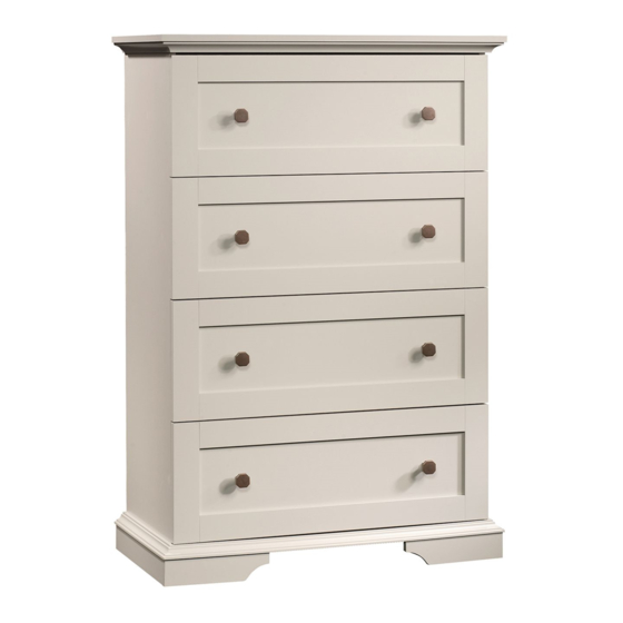
4-Drawer Chest
New Gran e Collection | Model 420021
Need help? Visit Sauder.com to view video assembly tips or chat with a live rep.
Prefer the phone? Call 1-800-523-3987.
Share your journey!
WARNING
CHOKING HAZARD - Small Parts
Not for children under 3 years.
Adult assembly required.
NOTE: THIS INSTRUCTION
BOOKLET CONTAINS IMPORTANT
SAFETY INFORMATION.
PLEASE READ AND KEEP FOR
FUTURE REFERENCE.
En lish p 1-24
Français p 25-28
Español p 29-32
Lot # 391194
06/07/16
Purchased: __________________
Be sure to ive us a rin before
makin any returns. 1-800-523-3987
Advertisement

Related Manuals for Sauder New Grange 420021


Summary of Contents for Sauder New Grange 420021
- Page 1 New Gran e Collection | Model 420021 NOTE: THIS INSTRUCTION BOOKLET CONTAINS IMPORTANT SAFETY INFORMATION. Need help? Visit Sauder.com to view video assembly tips or chat with a live rep. PLEASE READ AND KEEP FOR FUTURE REFERENCE. Prefer the phone? Call 1-800-523-3987.
- Page 2 Assembly Tools Required Part Identifi cation No. 2 Phillips Screwdriver Tip Shown Actual Size Hardware Identifi cation Assembly Steps 6-24 Hammer Not actual size Français 25-28 Español 29-32 Skip the power trip. Safety 33-34 This time. Warranty Pa e 2 420021 www.sauder.com/services...
- Page 3 DRAWER RIGHT SIDE (4) TOP RIGHT MOLDING (1) LEFT PLINTH (1) DRAWER LEFT SIDE (4) BACK (1) RIGHT PLINTH (1) D183 DRAWER BACK (4) BOTTOM FRONT MOLDING (1) D988 DRAWER BOTTOM (4) BOTTOM LEFT MOLDING (1) D183 D988 www.sauder.com/services 420021 Pa e 3...
- Page 4 This is a permanent label. Do not attempt to remove! 04/10 332296 (Refer to the last step for proper location and application) SAFETY DRYWALL NAIL - 26 METAL PIN - 2 ANCHOR - 1 Pa e 4 420021 www.sauder.com/services...
- Page 5 12S BROWN 1" FLAT HEAD SCREW - 3 BROWN 1-1/2" FLAT HEAD SCREW - 7 BLACK 2-1/4" FLAT HEAD SCREW - 4 30S BLACK 1-9/16" FLAT HEAD SCREW - 20 SILVER 1/2" MACHINE SCREW - 8 www.sauder.com/services 420021 Pa e 5...
- Page 6 Step 1 Look for this icon. It means a video assembly tip is available at www.sauder.com/services/tips Assemble your unit on a carpeted fl oor or on the empty å carton to avoid scratchin your unit or the fl oor. Scan this QR code or go to this address: http://qr.sauder.com/?ID=1801...
- Page 7 HIDDEN CAMS pointin toward the ed es Some assembly of the BACK. (and snacks) required. Turn two CAM SCREWS (8F) into the exact holes shown å in the ENDS (A and B). Arrow Arrow www.sauder.com/services 420021 Pa e 7...
- Page 8 ENDS (A and B). Use sixteen GOLD 5/16" FLAT HEAD SCREWS (3S) throu h holes #1 and #3. *patent pendin lide system å GOLD 5/16" FLAT HEAD SCREW (16 used in this step) Glide end Glide end Pa e 8 420021 www.sauder.com/services...
- Page 9 SCREW (1S) throu h the METAL BRACKET and into the LEFT END. BLACK 9/16" LARGE HEAD SCREW (3 used in this step) Ed e with CAM DOWELS f a c S u r w i t h D E N H I D www.sauder.com/services 420021 Pa e 9...
- Page 10 HIDDEN CAMS must be completely Maximum Arrow ti htened. HIDDEN 210 de rees CAMS that are not completely ti htened may loosen, and parts may separate. To Minimum completely ti hten: 190 de rees Pa e 10 420021 www.sauder.com/services...
- Page 11 S u r o u t w i t h D E N H I D Ed e with CAM DOWELS BLACK 9/16" LARGE HEAD SCREW (1 used for the METAL BRACKET) www.sauder.com/services 420021 Pa e 11...
- Page 12 Don't worry. It isn't Rome. This can be built in a day. Use your hammer to tap the MOLDING CONNECTORS (17F) into the notches in the TOP MOLDINGS. Flat end Flat surface Flat end Flat surface Flat surface Pa e 12 420021 www.sauder.com/services...
- Page 13 Fasten one end of the SAFETY STRAP (60M) to the TOP (C). (1 used for the SAFETY STRAP) å Use one BLACK 9/16" LARGE HEAD SCREW (1S). BROWN 1-1/2" FLAT HEAD SCREW (7 used in this step) www.sauder.com/services 420021 Pa e 13...
- Page 14 Step Step 9 Fasten the ENDS (A and B) to the TOP MOLDINGS (H å and I). Ti hten four HIDDEN CAMS. Maximum Arrow 210 de rees Minimum 190 de rees Pa e 14 420021 www.sauder.com/services...
- Page 15 (4 used in this step) These holes must be here. An led ed e r f a w i t l e s Flat surface An led ed e Flat surface www.sauder.com/services 420021 Pa e 15...
- Page 16 Fasten the BOTTOM FRONT MOLDING (K) to the BOTTOM (D). å Use three BROWN 1" FLAT HEAD SCREWS (12S). An led ed e Flat surface BROWN 1" FLAT HEAD SCREW (3 used in this step) An led ed e Pa e 16 420021 www.sauder.com/services...
- Page 17 Fasten four CORNER BRACKETS (31G) to the SIDE SKIRTS (E) exactly å as shown. Use ei ht BLACK 9/16" LARGE HEAD SCREWS (1S). BLACK 9/16" LARGE HEAD SCREW (10 used in this step) Curved ed e www.sauder.com/services 420021 Pa e 17...
- Page 18 Use four BLACK 9/16" LARGE If you're doin this to HEAD SCREWS (1S). help a friend, don't leave without a bite. BLACK 9/16" LARGE HEAD SCREW (4 used in this step) Curved ed e Pa e 18 420021 www.sauder.com/services...
- Page 19 BOTTOM MOLDINGS (K, L, and M). Use ei ht BLACK 9/16" LARGE HEAD SCREWS (1S) throu h the BRACKETS and into the BOTTOM MOLDINGS. BLACK 9/16" LARGE HEAD SCREW (8 used in this step) This hole will not be used. www.sauder.com/services 420021 Pa e 19...
- Page 20 Now, completely ti hten the four SCREWS (1S) alon the bottom ed e of å NAIL the LARGE BACK (N). (26 used in this step) This hole must be here. BLACK 9/16" LARGE HEAD SCREW (4 used in this step) Pa e 20 420021 www.sauder.com/services...
- Page 21 NOTE: Before movin your unit to a di erent location, unscrew the SAFETY DRYWALL ANCHOR (61M) from your wall. å The nylon sheath will remain behind your wall. This end is fastened to the TOP. www.sauder.com/services 420021 Pa e 21...
- Page 22 Fasten the DRAWER BRACE (M67) to the DRAWER å å SIDES (D30 and D31) and DRAWER BRACE (M67). Use FRONT (O). Tighten one HIDDEN CAM. five BLACK 1-9/16" FLAT HEAD SCREWS (30S). Repeat this step for the other DRAWERS. Pa e 22 420021 www.sauder.com/services...
- Page 23 Repeat this step for the other DRAWERS. å Glide end Glide end 127K SILVER 1/2" MACHINE SCREW (8 used for the KNOB SETS) (4 screws per drawer) GOLD 5/16" FLAT HEAD SCREW (16 used in this step) www.sauder.com/services 420021 Pa e 23...
- Page 24 -If equipped with a drawer interlock system, do not defeat or remove it. Use of tip-over restraints may only reduce, but not eliminate, the risk of tip-over. 30 lbs. each Place the lide on the SLIDE behind the lide on the RAIL. Pa e 24 420021 www.sauder.com/services...
- Page 25 EXTRÉMITÉ DROITE ..........1 EXCENTRIQUE ESCAMOTABLE ....12 pour future référence. EXTRÉMITÉ GAUCHE ..........1 CHEVILLE D'EXCENTRIQUE ......10 Pour contacter Sauder en ce qui concerne cet DESSUS ................1 VIS D'EXCENTRIQUE ..........2 élément, faire référence DESSOUS ................1 17F CONNECTEUR DE MOULURE......4 au numéro de lot et...
- Page 26 14 mm NOIRE (1S) à travers la CONSOLE EN MÉTAL et dans REMARQUE : Ne pas trop serrer les VIS dans le DESSUS. l’EXTRÉMITÉ GAUCHE. Fixer une extrémité de la SANGLE DE SÉCURITÉ (60M) au DESSUS (C). Utiliser une VIS TÊTE LARGE 14 mm NOIRE (1S). Pa e 26 420021 www.sauder.com/services...
- Page 27 fi xer les chants supérieur et latéraux du GRAND ARRIÈRE (N) à VIS TÊTE LARGE 14 mm NOIRES (1S). l'élément à l'aide des CLOUS (1N). Maintenant, serrer complètement les quatre VIS (1S) dans le chant inférieur du GRAND ARRIÈRE (N). www.sauder.com/services 420021 Pa e 27...
- Page 28 4 Fixer l'ARRIÈRE DE TIROIR (D183) aux CÔTÉS DE TIROIR (D30 et D31) et à l’ENTRETOISE DE TIROIR (M67). Utiliser cinq VIS TÊTE PLATE 40 mm NOIRES (30S). Répéter cette étape pour les autres TIROIRS. Pa e 28 420021 www.sauder.com/services...
- Page 29 EXTREMO IZQUIERDO ..........1 BIELA DE EXCÉNTRICO ........2 pour future référence. PANEL SUPERIOR ............1 17F CONECTOR DE MOLDURA ........4 Pour contacter Sauder en ce qui concerne cet FONDO .................1 SOPORTE DE METAL ..........4 élément, faire référence D30 LADO DERECHO DE CAJÓN ......4 31G MÉNSULA DE ESQUINA ........4...
- Page 30 Fije un extremo de la CORREA DE SEGURIDAD (60M) al PANEL CABEZA GRANDE de 14 mm (1S) a través del SOPORTE DE SUPERIOR (C). Utilice un TORNILLO NEGRO DE CABEZA METAL y en el EXTREMO IZQUIERDO. GRANDE de 14 mm (1S). Pa e 30 420021 www.sauder.com/services...
- Page 31 Empuje el DORSO GRANDE hacia la parte inferior de la unidad y fi je los bordes superiores y laterales del DORSO GRANDE (N) a la unidad utilizando los CLAVOS (1N). Ahora, apriete los cuatro TORNILLOS (1S) por completo en el borde inferior del DORSO GRANDE (N). www.sauder.com/services 420021 Pa e 31...
- Page 32 4 Fije el DORSO DE CAJÓN (D183) a los LADOS DE CAJÓN (D30 y D31) y a la RIOSTRA DE CAJÓN (M67). Utilice cinco TORNILLOS NEGROS DE CABEZA PERDIDA de 40 mm (30S). Repita este paso para los otros CAJONES. Pa e 32 420021 www.sauder.com/services...
- Page 33 TOUJOURS déchar er les tablettes et les tiroirs, en commençant par les surface supérieures, avant de déplacer le meuble. NE JAMAIS pousser ou tirer un meuble sur de la moquette. Demander à une autre personne de le soulever correctement pour le déplacer et/ou le repositionner. www.sauder.com/services 420021 Pa e 33...
- Page 34 SIEMPRE descar ue los estantes y cajones, empezando con las superfi cies superiores, antes de moverlo. NUNCA empuje ni tire de los muebles sobre una alfombra. Obten a que un ami o le ayude a levantarlo correctamente para moverlo y/o reposicionarlo. Pa e 34 420021 www.sauder.com/services...
- Page 35 à compter de la date d'achat la première fois et qui sont si nalés à Sauder dans les limites de couverture de la contre tout défaut de matériaux ou de fabrication des composantes de mobilier Sauder.
- Page 36 Dear Valued Customer: So, how did it o? Thanks so much for choosin Sauder® furniture. I hope the Set a world record for speed? purchase and assembly process was a positive experience Feelin ood about yourself? and you feel ood about the furniture you just built. If you Nice.
Need help?
Do you have a question about the New Grange 420021 and is the answer not in the manual?
Questions and answers