
Related Manuals for Vimar 01740


Summary of Contents for Vimar 01740
- Page 1 Manuale installatore Installer manual 01740 Rivelatore IR a tenda PET immune IR motion tent detector PET immune By-alarm...
-
Page 3: Table Of Contents
By-alarm ITALIANO 1. CARATTERISTICHE …………………………………………………………………………………………………… 2 2. IL RIVELATORE E LE SUE PARTI …………………………………………………………………………………… 2 3. COLLEGAMENTI ……………………………………………………………………………………………………… 3 3.1 Collegamento alla centrale ………………………………………………………………………………………… 3 3.2 Collegamento resistenza di fine linea ……………………………………………………………………………… 5 4. CONFIGURAZIONE DEL RIVELATORE …………………………………………………………………………… 5 4.1 Configurazione del LED (Dip-switch 1) …………………………………………………………………………… 6 4.2 Configurazione Uscita allarme (Dip-switch 2) ……………………………………………………………………... -
Page 4: Caratteristiche
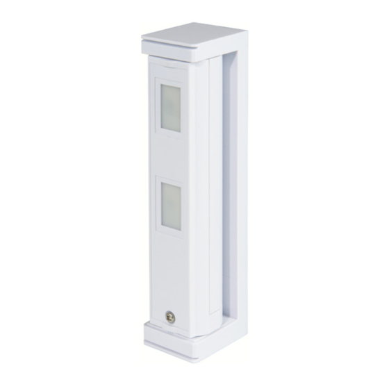
By-alarm Caratteristiche - Il rivelatore e le sue parti Rivelatore By-alarm a tenda per la protezione di varchi ed infissi quali porte, finestre, terrazzi coperti, corridoi di passaggio e vetrate, rilevazione a tendina a portata breve con lente regolabile fino a 2 m o 5 m, PET immune, funzione di antimascheramento, 1 uscita a relè... -
Page 5: Collegamenti
By-alarm Collegamenti 3. COLLEGAMENTI Attenzione: • L'uscita antimascheramento viene riconosciuta come Uscita di guasto. • Per le generiche resistenze di bilanciamento si veda il par. 3.2. – C TR TP TP Cavi di alimentazione. Lunghezza max Diametro 12 V 14 V AWG22 (0,33 mm 290 m 620 m... - Page 6 By-alarm Collegamenti Doppio bilanciamento – C TR TP TP 4.7 k 3.3 k All'ingresso allarme della centrale Triplo bilanciamento – C TR TP TP 4.7 k 15 k 3.3 k All'ingresso allarme della centrale...
-
Page 7: Collegamento Resistenza Di Fine Linea
By-alarm Collegamenti - Configurazione del rivelatore 3.2 Collegamento resistenze di bilanciamento. Poichè le uscite di allarme e di guasto condividono il morsetto COM, effettuare i collegamenti come sotto indicato. Doppio EOL Relé d ‘allarme Relé di problemi Interruttore antimanomissione Dispositivo Dispositivo Morsetto Morsetto... -
Page 8: Configurazione Del Led (Dip-Switch 1)
By-alarm Configurazione del rivelatore 4.1 Configurazione del LED (Dip-switch 1) ON / ACCESO Posizione Funzioni LED ACCESO (impostazione predefinita) LED SPENTO OFF / SPENTO 4.2 Configurazione Uscita Allarme (Dip-switch 2) N.A. Posizione Funzioni N.A. USCITA N.A. (impostazione predefinita) N.C. USCITA N.C. N.C. -
Page 9: Segnalazioni Del Led
By-alarm Segnalazione del led - Diagrammi di copertura 5. SEGNALAZIONI DEL LED Il led segnala la condizione di allarme, il tentativo di mascheramento e la fase di riscaldamento del dispositivo. Lampeggiante Acceso SPENTO Stati del rivelatore Indicazioni del LED Riscaldamento •... -
Page 10: Installazione
By-alarm Installazione 7. INSTALLAZIONE 7.1 Avvertenze Non rimuovere la scheda. Non toccare la scheda, Altezza di montaggio. ad eccezione del DIP switch. 0 , 8 , 2 m E L O A L L P A R Direzione di rilevamento di una persona che si avvicina: 7.2 Procedura di installazione 1. - Page 11 By-alarm Installazione 3. Tenere sollevata la parte superiore della staffa e 4. Inserire il cavo proveniente dalla parete nel foro per rimuovere l'unità principale. il cablaggio sul fondo della staffa e infine montare quest'ultima sulla parete. Staffa Viti 3x20 Unità principale Spugna 5.
- Page 12 By-alarm Installazione 6. Determinare l'angolo di rilevamento orizzontale e collegare l'elemento di fissaggio. Quando l'unità è montata su un angolo, rivolta in avanti lungo la parete, scegliere il contrassegno guida posto sul lato opposto della parete. Verificare che l'elemento di fissaggio e la staffa si Quando l'unità...
-
Page 13: Walk Test
By-alarm Walk test - Regole di installazione - Conformità normativa 8. WALK TEST 1. Impostare il Dip-switch 1 (LED) su ON. 2. Verificare che il LED si illumini per 2 s quando viene effetuata la rilevazione. Rilevato Non rilevato 1234 1234 Nota: Il Dip-switch di default è... - Page 15 By-alarm ENGLISH 1. FEATURES ……………………………………………………………………………………………………………… 14 2. THE DETECTOR AND ITS PARTS …………………………………………………………………………………… 14 3. CONNECTIONS ………………………………………………………………………………………………………… 15 3.1 Connection to the control unit ……………………………………………………………………………………… 15 3.2 Line-end resistor connection ……………………………………………………………………………………… 17 4. DETECTOR CONFIGURATION ………………………………………………………………………………………… 17 4.1 LED configuration (Dip switch 1) …………………………………………………………………………………… 18 4.2 Alarm Output configuration (Dip switch 2) …………………………………………………………………………...
-
Page 16: English 1. Features
By-alarm Characteristics - The detector and its parts By-alarm curtain-effect detector to protect entrances and openings such as doors, windows, covered terraces, corridors and French doors, short-range curtain-effect detection with adjustable lens up to 2 m or 5 m, PET im- mune, anti-masking function, 1 NO or NC 28 VDC 0.1A relay output, surface mounting, 9.5-18 VDC 20 mA power supply. -
Page 17: Connections
By-alarm Connections 3. CONNECTIONS Caution: • The anti-masking output is recognised as a Fault output. • For generic balancing resistors, see para. 3.2. Power supply cables. Max. length Diameter 12 V 14 V AWG22 (0.33 mm 290 m 620 m AWG20 (0.52 mm 450 m 980 m... - Page 18 By-alarm Connections Double balancing – C TR TP TP 4.7 k 3.3 k To the control unit alarm input Triple balancing – C TR TP TP 4.7 k 15 k 3.3 k To the control unit alarm input...
-
Page 19: Line-End Resistor Connection
By-alarm Connections - Detector configuration 3.2 Balancing resistor connection. Since the alarm and fault outputs share the COM terminal, make the connections as indicated below. Double EOL Alarm relay Problem relay Tamper-proof 1-way switch Device Device Terminal Terminal Alarm Signalling Tamper-proof Tamper-proof positive (+) -
Page 20: Led Configuration (Dip Switch 1)
By-alarm Detector configuration 4.1 LED configuration (Dip switch 1) Position Functions LED ON (default setting) LED OFF 4.2 Alarm Output configuration (Dip switch 2) N.O. Position Functions N.O. OUTPUT N.O. (default setting) N.C. OUTPUT N.C. N.C. 4.3 PIR Sensitivity configuration (Dip switch 3) Position Functions NORMAL SENSITIVITY... -
Page 21: Led Signalling
By-alarm LED signalling - Cover diagrams 5. LED SIGNALLING The LED signals the alarm condition, the masking attempt and the device heating phase. Flashing Detector statuses LED indications Heating • The LED flashes even if DIP SWITCH 1 is set to “OFF” Flashes for approximately 60 seconds Alarm Lights up for 2 seconds. -
Page 22: Installation
By-alarm Installation 7. INSTALLATION 7.1 Warnings Do not remove the board. Do not touch the board, with the Mounting height. exception of the DIP switch. 0 . 8 f r o m . 2 m t o 1 A L L P A R Direction of detection of an approaching person: 7.2 Installation procedure... - Page 23 By-alarm Installation 3. Keep the upper part of the bracket raised and remove 4. Insert the cable originating from the wall in the wiring the main unit. hole on the base of the bracket and then mount the latter onto the wall. Mounting bracket Screws 3x20...
- Page 24 By-alarm Installation 6. Determine the horizontal detection angle and connect the fixing element. When the unit is installed in a corner, facing forward along the wall, choose the guide mark situated on the opposite side of the wall. Ensure the fixing element and mounting bracket When the unit is installed on Align the detection area to ensure it is...
-
Page 25: Walk Test
By-alarm Walk test - Installation rules - Regulatory compliance 8. WALK TEST 1. Set Dip switch 1 (LED) to ON. 2. Check that the LED lights up for 2 s when detection takes place. Detected Not detected 1234 1234 Note: The Dip switch is set to ON by default. 3. - Page 26 Viale Vicenza, 14 36063 Marostica VI - Italy www.vimar.com 49401630A0 02 2012...
Need help?
Do you have a question about the 01740 and is the answer not in the manual?
Questions and answers