
Related Manuals for Vimar 01527


Summary of Contents for Vimar 01527
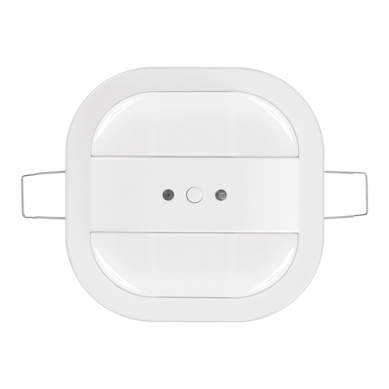
- Page 1 Installer manual 01527 KNX compact luminous motion detector 01529.1 KNX luninous motion detector...
- Page 2 Please keep this manual in a safe place. If you pass the device on, also include this manual. Vimar accepts no liability for failure to observe the instructions in this manual. If you require additional information or have questions about the device, please contact Vimar or visit our Internet site at: www.vimar.com...
-
Page 3: Table Of Contents
Contents 1. Safety …………………………………………………………………………………………………………………………………………………………………………………… 1.1 Used symbols ………………………………………………………………………………………………………………………………………………………………………… 1.2 Intended use ………………………………………………………………………………………………………………………………………………………………………… 1.3 Improper use ………………………………………………………………………………………………………………………………………………………………………… 1.4 Target group / qualification of personnel ………………………………………………………………………………………………………………………………………… 1.5 Safety instructions …………………………………………………………………………………………………………………………………………………………………… 2. Information on protection of the environment …………………………………………………………………………………………………………………………… 3. Product description ……………………………………………………………………………………………………………………………………………………………… 3.1 Device overview ……………………………………………………………………………………………………………………………………………………………………... -
Page 4: Safety
Each use not listed in chapter 2.2 is deemed improper use and can lead to personal injury and damage to property. VIMAR is not liable for damages caused by use deemed contrary to the intended use of the device. The associated risk is borne exclusively by the user/operator. -
Page 5: Safety Instructions
Safety - Information on protection of the environment 1.5 Safety instructions Warning Electric voltage! Risk of death and fire due to electric voltage of 230 V. Dangerous currents flow through the body when coming into direct or indirect contact with live components. This can result in electric shock, burns or even death. -
Page 6: Product Description
The device can be mounted either in the ceiling via hollow-wall mounting or on the ceiling via the optionally available surface-mounted housing (article 01529.1.S and 01527.S). The mounting instructions are enclosed with the surface-mounted housing. The overall function of the device also depends on the mounting height. -
Page 7: Description Of Functions
• PM: Also activities while seated. 01527 does not only switch lamps but can also dim them. This makes constant light control much more precise and maintains the brightness level in the room at the desired level. The integrated HVAC function makes it possible to control heating, ventilation and air-conditioning in the respective detection range when someone is present. - Page 8 Product description - Constant light switch The constant light switch switches on lamps in the room as soon as movement of a person is detected and the desired brightness value is not attained by the entering daylight alone. The programmed setpoint minus hysteresis is maintained as long as people are in the detection range. The application detects when the entering daylight is sufficient.
- Page 9 Product description 12:00 A : Artificial light curve of light row 1 B : Artificial light curve of light row 2 C : Sunlight curve Control parameters: 1 : Setpoint (lx) 2 : Delay time after switch-on up to measurement of the artificial light component 3 : Minimum time above the switch-off threshold (minutes) Fig.
-
Page 10: Detection Range
The reference level for the detection of seated activities is approx. 0.8 m. At this height, the detection range, such as for the 01527 detector is 6.5 m in diameter (mounting height of the presence detector = 3 m). -
Page 11: Technical Data
-5° C...+45 °C IP 20 Protection -20 °C...+70 °C Storage temperature Table 5: Technical data 4.2 Dimensions 01527 01529.1 All dimensions are in mm. All dimensions are in mm. FIg. 7: 01527 and 01529.1 presence detectors 4.3 Connection Fig. 8: Electrical connection... -
Page 12: Mounting
Wide outer detection range Detection ranges (seated person) (B2) (walking person) 2,5 m 5 m max. 6,5 m max. 01527 6,5 m max. 8 m max. 9 m max. 10,5 m max. 2,5 m 8 m max. 10 m max. -
Page 13: Sources Of Interference
Mounting 5.3 Sources of interference The presence detector detects the movement of heat sources. If a foreign heat source is in close proximity, this can cause false triggering. Here a distinction must be made between foreign heat sources and limited visibility as a source of interference. - Limited view of the device The detection range of the device may be obstructed by various objects, e.g.: - Lamp strip that have been installed lower than the device. -
Page 14: Mounting / Installation
Mounting - Heat sources without interference effect If the temperature changes only slowly, this will not affect the switching behaviour of the device, e.g. on: - Radiators (distance > 1.5 m) - Surfaces heated by the sun - EDP systems (computers, monitors) - Ventilation systems, when warm air does not flow directly into the device Fig. - Page 15 Mounting Carefully slide the connected device into the recess. The clamps must be pressed toward the top. Ø 68 mm • After the insertion the clamps fold down automatically and hold the device in the correct position. • A subsequent alignment is still possible! Figg.
- Page 16 Mounting • Now slide the connected device into the surface mounted housing according to the illustration shown opposite. Take note of the guide rails. This is the only way the device can be inserted! • Now turn the device in a clock-wise direction until it is aligned with the surface-mounted housing. Note: Dismantling is carried out in the reverse order! Figg.
-
Page 17: Commissioning
Commissioning 6. Commissioning 6.1 Software To start the device a physical address must be assigned first. The assignment of a physical address and setting of parameters is carried out with the ETS commis- sioning software (ETS 4/ only native application; ETS 5/ only native application). 6.1.1 Preparatory steps 1. - Page 18 Commissioning • Use objects for brightness adjustment There is the option of carrying out a brightness adjustment for daylight and artificial light via the brightness detection application with the aid of the following three objects: (a) Brightness adjustment (daylight) (b) Brightness adjustment (output 1) (c) Brightness adjustment (output 2) In the event that artificial light and daylight are perceived similarly by the sensor, or the movement detector application is used exclusively, only the absolute brightness value need be corrected.
- Page 19 Commissioning 6.1.7 Additional comments Setpoint Note: The following information is relevant only if no adjustment of brightness has been carried out. Please note that the lux value to be set in the parameters does not correspond to the value required at the height of the desk. The light sensor is installed on the ceiling and can only measure the luminosity that is reflected from the opposite surfaces.
-
Page 20: Updating Options
Updating options - Maintenance 7. Updating options Always use the latest firmware. The latest download files for the firmware update are contained in the electronic catalogue. They are also available via the KNX online shop. A firmware update is carried by means of an ETS application via the bus. Note: Please adhere to the current information about the download files. -
Page 21: Description Of Application And Parameters
Description of application and parameters Applications program - Overview of applications - "Detector" application 9. Description of application and parameters 9.1 Applications program The following applications program is available: • Presence detector xxx KNX TP/1 9.2 Overview of applications The application program for the devices contains the KNX applications listed in the following: •... - Page 22 Description of application and parameters "Detector" application 9.3.4 General parameters - Output object sends at Options: Switching on/off Switching on Switching off - Switch-on/switch-off: Sends a telegram at the start of movement and at the end of switch-off delay. - Switch-on: Only sends a telegram at the start of movement. - Switch-off: Only sends a telegram at the end of switch-off delay.
- Page 23 Description of application and parameters "Detector" application 9.3.9 General parameters - Switch-off delay (hh:mm:ss) Options: 0.00.10 .. 0.05.00 .. 18.12.15 - The switch-off delay is the time period between the last movement detected and the sending of the telegram "Value for switch-off". If movement is detected again within this period, the switch-off delay timer is started again.
- Page 24 Description of application and parameters "Detector" application 9.3.14 Extended parameter settings - Use of a two-stage switch-off Note: This parameter is only displayed when "Output is of type" is set on 1 byte 0 - 100% or 1 byte 0 - 255. Options: - No: The detector has a switch-off delay and, following the switch-off delay, transmits what has been set under the "Value for switch-off"...
- Page 25 Description of application and parameters "Detector" application 9.3.20 Extended parameter settings - Use of object for test mode Options: - No: There is no possibility to set the detector to test mode to test the detection range. - Yes: There is a separate 1-bit test mode activation object (input) for activating the test mode with a 1. The function is reset again with the receipt of a 0 on this object or automatically after 10 minutes.
- Page 26 Description of application and parameters "Detector" application 9.3.25 Brightness parameter - Use of object for detection independent of brightness Options: - No: There is no separate object for detection independent of brightness. - Yes: A 1-bit communication object for brightness-independent detection (input) is being enabled. This object allows the detector to be switched independ- ent of brightness.
- Page 27 Description of application and parameters "Detector" application 9.3.31 Brightness parameter - Use object for external brightness-value threshold Options: - No: There is no separate external brightness-value threshold object. - Yes: A 2-byte external brightness-value threshold communication object (input) is being enabled. This can be used to change the switching threshold at which the detector is activated.
- Page 28 Description of application and parameters "Detector" application 9.3.38 Enable - Use of enable detector object Options: - No: There is no object with which the detector can be blocked or enabled. - Yes: A 1-bit enable movement communication object (input) is being enabled. This object allows the detector to be enabled or blocked. No telegrams are sent by the detector during blockage.
- Page 29 Description of application and parameters "Detector" application 9.3.43 Extended parameter settings (monitoring) - Monitoring time window Options: 0.00.01 .. 0.00.30 .. 00:10:00 hh:mm:ss - The monitoring time window correlates with minimum activity in the monitoring time window. The telegram is only sent when a movement is detected within the monitoring time window, e.g.
-
Page 30: Constant Light Switch Application
Description of application and parameters "Constant light switch" application 9.4 Constant light switch application 9.4.1 General parameters - Output is of type Options: 1 bit 1 byte 0...100% 1 byte 0...255 Light scene number (1-64) RTC operating mode switchover (1 byte) 2-byte float - 1 bit: Intended for switch actuators. - Page 31 Description of application and parameters "Constant light switch" application 9.4.6 General parameters - Brightness-value threshold internal (lux) Options: 1 .. 20 .. 1000 - This is used to set the desired brightness of the room. Below this threshold - hysteresis the presence detector switched at movement. The presence detector switches off again when the measured brightness - artificial light component = brightness-value threshold + hysteresis.
- Page 32 Description of application and parameters "Constant light switch" application Used movement detection Options: Only internal Only external Internal and external - Only internal: The presence detector responds only to movement measured internally. - Only external: The presence detector responds only to telegrams that are received via the slave object (input). - Internal and external: The presence detector responds to movements measured internally and to external telegrams that are received via the slave object (input).
- Page 33 Description of application and parameters "Constant light switch" application Value for switching on output 2 Options: - On: When the presence detector detects movement, value 1 is sent via the bus. - Off: When the presence detector detects movement, value 0 is sent via the bus. Value for switching off output 2 Options: - Off: If movement is no longer detected and the switch-off delay has expired, value 0 is sent via the bus.
- Page 34 Description of application and parameters "Constant light switch" application 9.4.14 Extended parameters - Use of actual brightness object Options: - No: There is no extra actual brightness object - Yes: A 2-byte actual brightness (output) communication object is being enabled. This object outputs the corrected measured brightness (corrected daylight + corrected artificial light) which is used by the constant light switch.
- Page 35 Description of application and parameters "Constant light switch" application 9.4.21 Extended parameters - Pause time (ss.fff) Options: 00.100 .. 01.250 .. 59.999 - The set pause time is started after the detector has been switched off due to expiry of the switch-off delay or when a switch-off telegram is received on objects external push-button or actuator status.
- Page 36 Description of application and parameters "Constant light switch" application 9.4.26 Enable - Enable with Options: ON telegram OFF telegram - ON telegram: With the receipt of value 1 on the enable movement (input) object the detector is enabled and blocked with value 0. - OFF telegram: With the receipt of value 0 on the enable movement (input) object the detector is enabled and blocked with value 1.
-
Page 37: Constant Light Controller" Application
Description of application and parameters "Constant light controller" application 9.5 "Constant light controller" application 9.5.1 General parameters - Output is of type Options: 1 byte 0...100 % 1 byte 0...255 - 1 byte 0...100 %: For activating dimmers. - 1 byte 0...255: For actuators, which are activated with a value of between 0 and 255. Note: If the type of output is changed, also the options for setting the parameters change: ›... - Page 38 Description of application and parameters "Constant light controller" application 9.5.7 General parameters - Hysteresis (%) Options: 10 .. 12 .. 100 - Switching threshold = setpoint ± hysteresis The hysteresis prevents excessive switching when the current ambient brightness is close to the brightness threshold. 9.5.8 General parameters - Switch-off delay (hh:mm:ss) Options: 0.00.10 ..
- Page 39 Description of application and parameters "Constant light controller" application 9.5.13 Extended parameters - Use of a two-stage switch-off Options: - No: The detector has a switch-off delay and, following the switch-off delay, transmits what has been set under the "Value for switch-off" parameter. - Yes: After the switch-off delay the detector first switches to the set reduced brightness and only then sends the value set under the "Value for switch-off"...
- Page 40 Description of application and parameters "Constant light controller" application 9.5.17 Extended parameters - Dimming step size darker (1 to 15) Options: 1 .. 2 .. 15 - Here the step size for reducing the dimming value during dimming darker is specified. Note: If the dimming step size is set too high, the dimming steps will be clearly visible in the lighting.
- Page 41 Description of application and parameters "Constant light controller" application 9.5.23 Extended parameters - Use of object for setpoint brightness Options: - No: There is no separate brightness object. - Yes: A 2-byte setpoint brightness (input/output) communication object is being enabled. This can be used to change the switching threshold, while the presence detector is activated or deactivated.
- Page 42 Description of application and parameters "Constant light controller" application 9.5.29 Extended parameters - Control speed adjustment through blind inputs Options: - No: There are no separate settings for adjusting the control speed when a Venetian blind control unit is available. - Yes: There are separate settings: control parameters for the movement of blinds.
- Page 43 Description of application and parameters "Constant light controller" application 9.5.37 Extended parameters - Pause time (ss.fff) Options: 00.100 .. 01.250 .. 59.999 - The set pause time is started after the detector has been switched off due to expiry of the switch-off delay or when a switch-off telegram is received on objects external push-button or actuator status.
- Page 44 Description of application and parameters "Constant light controller" application 9.5.42 Enable - Enable with Options: ON telegram OFF telegram - ON telegram: With the receipt of value 1 on the enable movement (input) object the detector is enabled and blocked with value 0. - OFF telegram: With the receipt of value 0 on the enable movement (input) object the detector is enabled and blocked with value 1.
-
Page 45: Application "Hvac" (Heating, Ventilation, Air-Conditioning)
Description of application and parameters Application "HVAC" (Heating, ventilation, air-conditioning) 9.6 Application "HVAC" (Heating, ventilation, air-conditioning) 9.6.1 General parameters - Output is of type Options: 1 bit 1 byte 0...100% 1 byte 0...255 Light scene number (1-64) RTC operating mode switchover (1 byte) 2-byte float - 1 bit: Intended for switch actuators. - Page 46 Description of application and parameters Application "HVAC" (Heating, ventilation, air-conditioning) 9.6.4 General parameters - Value for switch-off Options: Auto Comfort Standby Frost/heat protection - Auto: When movement is no longer detected and the switch-off delay has expired, value 0 (auto) is sent superimposed via the HVAC object on the bus to the operating mode object, to reset the RTC into automatic mode.
- Page 47 Description of application and parameters Application "HVAC" (Heating, ventilation, air-conditioning) 9.6.9 Extended parameters - Operating mode Options: Heating/air-conditioning Ventilation - Heating/air-conditioning: The switch-on delay time starts with a movement. If movement is no longer detected during the switch-on delay time, the switch-on delay time is reset.
- Page 48 Description of application and parameters Application "HVAC" (Heating, ventilation, air-conditioning) 9.6.13 Extended parameters - Use of object for force-position Options: - No: There is no separate force-position object. - Yes: There is a separate 1-bit force-position object (input). When an On telegram is received via the object, the presence detector is blocked and the value under force-position is sent via the HVAC object.
- Page 49 Description of application and parameters Application "HVAC" (Heating, ventilation, air-conditioning) 9.6.18 Enable - After bus voltage recovery the device is Options: Enabled Blocked - Enabled: The device is enabled and functions normally when the bus voltage is interrupted or the device has been re-programmed, as well as after a reset. - Blocked: The device is blocked and must be enabled for normal function when the bus voltage is interrupted or the device has been re-programmed, as well as after a reset.
-
Page 50: Brightness Detection" Application
Description of application and parameters "Brightness detection" application 9.7 "Brightness detection" application 9.7.1 General parameters - Sending of brightness every (hh:mm:ss) Options: 0.00.05 .. 0.00.30 .. 18.12.15 - Here it is specified how often the brightness is sent on the bus. 9.7.2 General parameters - Use of object for LED Options: - No: There is no separate LED object. -
Page 51: Rtc Object" Application
Description of application and parameters "RTC object" application 9.8 "RTC object" application 9.8.1 General - Device function Options: Single device Master device Slave device - Single device: The device is used singly in a room as room temperature controller. - Master device: At least two room temperature controllers are located in one room. One device is to be set up as a master device, while the others are to be programmed as slave devices / temperature sensors. - Page 52 Description of application and parameters "RTC object" application 9.8.4 General - Additional functions Options: - This parameter enables additional functions and communication objects, e.g. window contact and presence detector. 9.8.5 General - Send cyclic "In operation" (min) Options: Setting option between 5 - 3000 minutes - The "In operation"...
- Page 53 Description of application and parameters "RTC object" application 9.8.9 Heating control - P-component (x 0.1°C) Options: Setting option between 10 - 100 - The P-component refers to the proportional band of a control. It fluctuates around the setpoint value and can be used to influence control speed with a PI controller.
- Page 54 Description of application and parameters "RTC object" application 9.8.16 Basic stage heating - Control value difference for sending of heating control value Options: 10 % Send cyclic only The control values of the 0 - 100% PI continuous controller are not transmitted after every calculation. Instead, they are transmitted when the calculation results in a value that is different enough to the previous sent value to make a transmission meaningful.
- Page 55 Description of application and parameters "RTC object" application 9.8.22 Control of additional heating stage - Control value type Options: 2-point 1 bit, Off/On 2-point 1 byte, (0/100%) PI continuous, 0-100% PI PWM, On/Off Fan coil The actuation of the control valve is determined by the selection of the controller type. - 2-Point 1 Bit, Off/On: The 2-point control is the simplest type of control.
- Page 56 Description of application and parameters "RTC object" application 9.8.26 Control of additional heating stage - Temperature difference to basic stage (x 0.1°C) Options: Setting option between 0 - 255 The setpoint temperature of the additional stage is defined as a function of the current setpoint temperature of the base stage and is expressed as a differ- ence.
- Page 57 Description of application and parameters "RTC object" application 9.8.32 Additional heating stage - Cyclic sending of the control value (min) Options: Setting option between 1 - 60 minutes The current control value used by the device can be cyclically transmitted to the bus. Note: This parameter is only available when the "Control value type"...
- Page 58 Description of application and parameters "RTC object" application 9.8.36 Cooling control - Cooling type Options: PI continuous, 0 – 100% and PI PWM, On/Off: • Area (e.g. cooling ceiling) 5°C 240 min • Free configuration Fan coil • Fan coil 4 °C 90 min •...
- Page 59 Description of application and parameters "RTC object" application 9.8.43 Basic stage cooling - Hysteresis (x 0.1°C) Options: Setting option between 3 - 255 The hysteresis of the two-point controller specifies the fluctuation range of the controller around the setpoint value. The lower switching point is located at "Setpoint value minus hysteresis"...
- Page 60 Description of application and parameters "RTC object" application 9.8.48 Control of additional cooling stage Note: Only available when the "Device function" parameter is set on either "Single device" or "Master device" and the control function parameter is set on either "Cooling with additional stage"...
- Page 61 Description of application and parameters "RTC object" application 9.8.52 Control of additional cooling stage - Extended settings Options: - This parameter enables additional functions and communication objects, e.g. "Additional cooling stage". 9.8.53 Additional cooling stage Note: Only available when the "Extended settings" parameter under "Control of additional cooling stage" is set on "Yes". 9.8.54 Additional cooling stage - Mode of the control value Options: Normal...
- Page 62 Description of application and parameters "RTC object" application 9.8.59 Basic cooling stage - Minimum control value for basic load (0 - 255) Options: Setting option between 0 - 255 The minimum control value of the PI controller defines the minimum value output by the controller. If a minimum value greater than zero is chosen, the control- ler will not output a lower value, even if it calculates a value that is lower.
- Page 63 Description of application and parameters "RTC object" application 9.8.65 Combined heating and cooling modes - Heating/cooling control value output Options: Via 1 object Via 2 objects This parameter is used to define whether the control value is transmitted to the climate control actuator using one or two objects. If the climate control actuator has separate control value inputs for heating and cooling, or if separate actuators are used, then the option "Via 2 objects"...
- Page 64 Description of application and parameters "RTC object" application 9.8.72 Setpoint settings - Reduction for standby heating (°C) Options: Setting option between 10 - 40 Specifies the temperature in heating mode when nobody is present. On devices with a display, this mode is indicated by the standby icon. Note: This parameter is only available when the "Control function"...
- Page 65 Description of application and parameters "RTC object" application 9.8.79 Setpoint settings - Display indicates Options: Current set value Relative set value The display can indicate either the absolute or relative setpoint value. - Current set value: On devices with a display, the setpoint is shown as an absolute temperature, e.g. 21.0°C. - Relative set value: On devices with display, the setpoint is indicated as a relative value, e.g.
- Page 66 Description of application and parameters "RTC object" application 9.8.87 Setpoint adjustment - Resetting of the manual adjustment for receipt of a basic set value Options: Activating this parameter will cause the manual adjustment to be deleted and the new setpoint value to be provided when a new value is received via the "Basic setpoint"...
- Page 67 Description of application and parameters "RTC object" application 9.8.93 Temperature reading - Weighting of internal measurement (0 to 100%) Options: Setting option between 0 - 15 Specifies the weighting of the internal measurement at a level between 0% and 100%. Note: This parameter is only available when the "Inputs of weighted temperature reading"...
- Page 68 Description of application and parameters "RTC object" application 9.8.100 Temperature reading — Operating mode for fault Options: Cooling Heating In the event of a failure of the actual temperature measurement, the device will no longer be able to independently specify the heating/cooling operating type.
- Page 69 Description of application and parameters "RTC object" application 9.8.107 Fan coil settings - Fan speed levels Note: This parameter is only available if the "Device function" parameter is set on either "Single device" or "Master device" and the "Control value type" parameter is set on "Fan coil".
- Page 70 Description of application and parameters "RTC object" application 9.8.114 Fan coil settings for heating - Speed level 1 to 5 up to control value (0 to 255) heating Options: Setting option between 0 - 255 In this parameter, the control values of the controller are assigned to fan speed levels. This assignment is used if the fan speed levels are transmitted together with the control values.
- Page 71 Description of application and parameters "RTC object" application 9.8.122 Summer compensation - Summer compensation Options: In order to save energy, and to ensure that the temperature difference occurring during entry and exit of a climate-controlled building stays within comfort- able limits, the excessive reduction of room temperature should be prevented during high temperatures in the summer ( Summer compensation according to DIN 1946).
- Page 72 Description of application and parameters "RTC object" application 9.8.125 Summer compensation - (Upper) exit temperature for summer compensation (°C) Options: Setting option between -127 - 127 The parameter defines the upper outside temperature value up to which temperature value the setpoint correction (summer compensation) is performed based on too high an outside temperature.
-
Page 73: Communication Objects - Presence Detector - Master
Description of application and parameters Communication objects - Presence detector - Master 9.9 Communication objects — Presence detector — Master 9.9.1 Px: switchover of manual operation Number Name Object function Data type 12 | 30 | 48 | 64 Px: Switchover of manual operation Input 1.001 switch This object is used to switch over from automatic mode to manual mode (default: 0 = automatic, 1 = manual). -
Page 74: Communication Objects - Presence Detector - Slave
Description of application and parameters Communication objects - Presence detector - Slave 9.10 Communication objects — Presence detector — Slave 9.10.1 Px: Enable movement Number Name Object function Data type 1 | 19 | 37 | 53 Px: Enable movement 1.001 switch The detector can be blocked or enabled via the object. -
Page 75: Communication Objects - Presence Detector - Monitoring
Description of application and parameters Communication objects - Presence detector - Monitoring 9.11 Communication objects — Presence detector — Monitoring 9.11.1 Px: Enable movement Number Name Object function Data type 1 | 19 | 37 | 53 Px: Enable movement Input 1.001 switch The detector can be blocked or enabled via the object. - Page 76 Description of application and parameters Communication objects - Presence detector - Constant light switch 9.12.4 Px: Slave Number Name Object function Data type Px: Slave 1.001 switch The constant light switch can be switched on with a 1 from a different movement or presence detector via the object. 9.12.5 Px: External brightness Number Name...
-
Page 77: Communication Objects - Presence Detector - Constant Light Controller
Description of application and parameters Communication objects - Presence detector - Constant light controller 9.13 Communication objects — Presence detector — Constant light controller 9.13.1 Px: Output 1 Number Name Object function Data type 1 | 19 Px: Output 1 Output 5.001 percentage (0...100%) 5.010 counter pulses (0...255) - Page 78 Description of application and parameters Communication objects - Presence detector - Constant light controller 9.13.8 Px: Enable presence Number Name Object function Data type 8 | 26 Px: Enable presence Input 1.001 switch The constant light controller can be blocked or enabled via the object. Enabling has priority over all other objects. 9.13.9 Px: Switch-off delay Number Name...
- Page 79 Description of application and parameters Communication objects - Presence detector - Constant light controller 9.13.15 Px: Brightness reduced according to switch-off delay Number Name Object function Data type 16 | 34 Px: Brightness reduced according to switch-off delay Input 7.005 time (s) If no movement is detected after the switch-off delay has expired, the function enters the programmed switch-off delay and then switches off.
-
Page 80: Communication Objects - Presence Detector - Hvac
Description of application and parameters Communication objects - Presence detector - HVAC 9.14 Communication objects — Presence detector — HVAC 9.14.1 P3: HVAC Number Name Object function Data type P3: HVAC Output 1.001 switch 5.001 percentage (0...100%) 5.010 counter pulses (0...255) 18.001 scene control 20.102 HAVC mode 9.* 2-byte float value... -
Page 81: Communication Objects - Presence Detector - Brightness Detection
Description of application and parameters Communication objects - Presence detector - Brightness detection 9.15 Communication objects — Presence detector — Brightness detection 9.15.1 BR: Brightness Number Name Object function Data type BR: Brightness Output 9.* 2-byte float value This object sends the brightness value calibrated via the daylight correction. 9.15.2 BR: Alarm Number Name... -
Page 82: Communication Objects - Object Rtc
Description of application and parameters Communication objects - Object RTC 9.16 Communication objects - Object RTC 9.16.1 Heating control value Number Name Object function Data type Heating control value Output 1. Switching (control value heating/cooling) 2. Percent (0...100%) Description: 1. This object is used to operate a switching actuating drive, e.g. a thermoelectric positioner, that is controlled by a switching/heating actuator. 2. - Page 83 Description of application and parameters Communication objects - Object RTC 9.16.5 Control On/Off Number Name Object function Data type 1. Control On/Off Output Switching 2. Control On/Off (master) Output Switching 3. Control On/Off (slave) Output Switching If a 0 telegram is received, the controller switches to OFF mode and regulates the temperature to the setpoint value for frost/heat protection. When the con- troller is switched on again, the remaining operating mode objects are queried in order to determine the new operating mode.
- Page 84 Description of application and parameters Communication objects - Object RTC 9.16.10 Local actual temperature Number Name Object function Data type Local actual temperature Output Switching Not visible! 9.16.11 Current setpoint Number Name Object function Data type Current setpoint Output 2-byte floating point value The object outputs the current setpoint temperature resulting from the following: the parameterized setpoint temperature of the current operation type and operating mode, the manual setpoint temperature adjustment, a change in the base setpoint temperature via the base setpoint value object.
- Page 85 Description of application and parameters Communication objects - Object RTC 9.16.15 Presence watchdog Number Name Object function Data type 1. Presence detector Input Switching 2. Presence detector (master/slave) Input Switching This object transmits the value 1 to the controller to signal that there are people in the room. If not other object with a higher priority is present, then the "Presence detector"...
- Page 86 Description of application and parameters Communication objects - Object RTC 9.16.20 Fan coil manual Number Name Object function Data type 1. Fan coil manual Output Switching 2. Fan coil manual (master)) Output Switching 3. Fan coil manual (slave) Output Switching Using this 1-bit communication object, a fan coil actuator can be placed in manual fan mode or returned to automatic fan mode.
- Page 87 Description of application and parameters Communication objects - Object RTC 9.16.26 Fan speed level 4 Number Name Object function Data type Fan speed level 4 Output Switching This 1-bit communication object is used to output the active status (1) of the fan speed level, while the other fan speed levels are deactivated (0), depending on the parameter setting.
- Page 88 Description of application and parameters Communication objects - Object RTC 9.16.32 Outside temperature for summer compensation Number Name Object function Data type Outside temperature for summer compensation Input 2-byte floating point value In order to save energy, and to ensure that the temperature difference occurring during entry and exit of a climate-controlled building stays within comfort- able limits, the reduction of room temperature by cooling devices should be limited as a function of the outside temperature (summer compensation).
- Page 89 Description of application and parameters Communication objects - Object RTC 9.16.38 Setpoint display Number Name Object function Data type 1. Setpoint display (master) Input / output 2-byte floating point value 2. Setpoint display (slave) Input / output 2-byte floating point value This 2-byte communication object must be connected to the respective slave communication object in order to synchronise the devices in the master/ slave configuration.
- Page 90 Description of application and parameters Communication objects - Object RTC 9.16.44 Confirm fan speed level Number Name Object function Data type 1. Confirm fan speed level (master) Input / output Percent (0...100%) 2. Confirm fan speed level (slave) Input / output Percent (0...100%) This 1-byte communication object must be connected to the respective slave communication object in order to synchronise the devices in the master/ slave configuration.
- Page 92 Viale Vicenza 14 36063 Marostica VI - Italy 01529.1-01527 EN 01 1705 www.vimar.com...
Need help?
Do you have a question about the 01527 and is the answer not in the manual?
Questions and answers