
Related Manuals for Vimar 01739


Summary of Contents for Vimar 01739
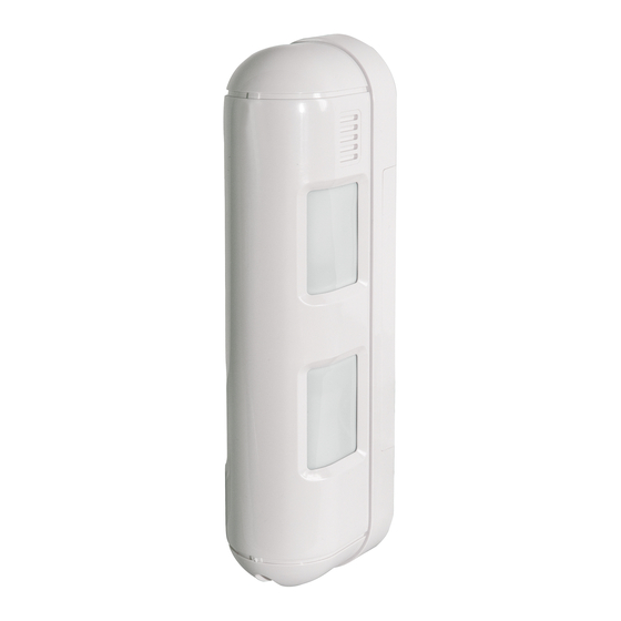
- Page 1 Manuale installatore Installer manual 01739 Rivelatore IR, 12m+12m, IP55, PET immune IR motion detector, 12m+12m, IP55, PET immune By-alarm...
-
Page 3: Table Of Contents
By-alarm ITALIANO 1. CARATTERISTICHE …………………………………………………………………………………………………… 2 2. IL RIVELATORE E LE SUE PARTI …………………………………………………………………………………… 2 2.1 Vista frontale ………………………………………………………………………………………………………… 3 3. COLLEGAMENTI ……………………………………………………………………………………………………… 3 3.1 Collegamento alla centrale ………………………………………………………………………………………… 4 3.2 Collegamenti per la segnalazione acustica di allarme dal buzzer del rivelatore ………………………………… 4 4. -
Page 4: Caratteristiche
By-alarm Caratteristiche - Il rivelatore e le sue parti Rivelatore By-alarm di presenza ad infrarossi passivi per la protezione di esterno edifici, rilevazione a tendina 12 metri su ciascun lato (sinistro e destro), PET immune, IP55, 1 ingresso per controllo acustico, 2 uscita a relè NO e NC 28 Vdc 0,2 A , installazione a parete, alimentazione 10-28 Vdc 38 mA. -
Page 5: Vista Frontale
By-alarm Collegamenti 2.1 Vista frontale Buzzer Dip-switch Selettore sinistro Selettore destro Tamper Foro ingresso cavi Morsetti di collegamento 3. COLLEGAMENTI Uscita allarme N.C. Uscita allarme N.A. Antiapertura N.C. Ingresso alimentazione Ingresso per segnalazione 10-28 V dc acustica allarme buzzer Cavi di alimentazione. Lunghezza max Diametro 12 V... -
Page 6: Collegamento Alla Centrale
By-alarm Collegamenti 3.1 Collegamento alla centrale Singolo bilanciamento 3.3 k All'ingresso allarme della centrale 3.3 k All'ingresso Tamper della centrale Doppio bilanciamento 4.7 k 3.3 k All'ingresso allarme della centrale 3.2 Collegamenti per la segnalazione acustica di allarme dal buzzer del rivelatore Senza tensione Con tensione Questo tipo di cablaggio va effettuato quando la cen-... -
Page 7: Configurazione Del Rivelatore
By-alarm Configurazione del rivelatore 4. CONFIGURAZIONE DEL RIVELATORE La configurazione viene effettuata attraverso i Dip-switch e i selettori presenti sulla scheda elettronica del dispositivo. 4.1 Regolazione della sensibilità • Per impostare la sensibilità massima posizionare il selettore di sinistra su HI La massima sensibilità... -
Page 8: Impostazione Per Walk Test
By-alarm Diagrammi di copertura 4.4 Impostazione per walk test • Posizionare il Dip-switch 3 in ON e impostare l'area di rilevazione desiderata (si veda il cap. 7). • Posizionare il selettore di destra su MAX o MIN per abilitare la segnalazione acustica. -
Page 9: Installazione
By-alarm Installazione 6. INSTALLAZIONE 6.1 Avvertenze 0,8 ~ 1,2 m Altezza di installazione Installare il rivelatore in verticale con Installare il rivelatore in modo che compresa tra 0,8 e 1,2 m. le zone superiori di rilevazione paral- le zone di rilevazione superiore ed lele al suolo. -
Page 10: Impostazione Dell'area Di Rilevazione
By-alarm Impostazione dell'area di rilevazione 5. Collegare i conduttori ai morsetti. Assicurarsi 5.1 In caso di utilizzo di cavi esterni: posizionare i cavi tra le spugne della base e - Far passare i conduttori attraverso l'apposito foro nella la piastra di fissaggio per evitare il passaggio di parte bassa e collegarli ai morsetti;... -
Page 11: Regolazione Della Portata Di Rilevazione
By-alarm Impostazione dell'area di rilevazione 1. Sbloccare le tre linguette per ogni lato del supporto 2. Per selezionare l'angolo desiderato (da 0 a 3°) spo- lente inserendo la lama di un cacciavite come da figu- stare le lente assicurandosi che sia sganciata dalla ra. - Page 12 By-alarm Impostazione dell'area di rilevazione • Regolare la portata di rilevazione facendo scorrere le lenti come da figura. Le zone inferiori sono regolabili sul lato di destra e su quello di sinistra in modo indipendente. Non premere con forza. Rimuovere il supporto delle lenti dal coperchio come illustrato nel par. 7.1. Far scorrere le lenti inferiori per regolare la portata di rilevazione.
-
Page 13: Regole Di Installazione
By-alarm Walk test - Regole di installazione - Conformità normativa 9. REGOLE DI INSTALLAZIONE • L’installazione deve essere effettuata da personale qualificato con l’osservanza delle disposizioni regolanti l’instal- lazione del materiale elettrico in vigore nel paese dove i prodotti sono installati. •... - Page 15 By-alarm ENGLISH 1. FEATURES ……………………………………………………………………………………………………………… 14 2. THE DETECTOR AND ITS PARTS …………………………………………………………………………………… 14 2.1 Front view …………………………………………………………………………………………………………… 15 3. CONNECTIONS ………………………………………………………………………………………………………… 15 3.1 Connection to the control unit ……………………………………………………………………………………… 16 3.2 Connections for the acoustic alarm signalling from the detector buzzer ……………………………………… 16 4.
-
Page 16: English 1. Features
By-alarm Characteristics - The detector and its parts By-alarm passive infrared presence detector for the protection of building exteriors, 12-metre curtain-effect detection on each side (left and right), PET immune, IP55, 1 input for acoustic control, 2 NO and NC 28 VDC 0.2 A relay outputs, surface mounting, 10-28 VDC 38 mA power supply. -
Page 17: Front View
By-alarm Connections 2.1 Front view Buzzer Dip switch Left selector Right selector Tamper Cable input hole Connection terminals 3. CONNECTIONS N.C. Alarm output N.O. Alarm output N.C. Tamper-proof Power supply input Input for buzzer alarm 10-28 V DC acoustic signalling Power supply cables. -
Page 18: Connection To The Control Unit
By-alarm Connections 3.1 Connection to the control unit Single balancing 3.3 k To the control unit alarm input 3.3 k To the control unit Tamper input Double balancing 4.7 k 3.3 k To the control unit alarm input 3.2 Connections for the acoustic alarm signalling from the detector buzzer No voltage With voltage This type of wiring should be done when the control... -
Page 19: Detector Configuration
By-alarm Detector configuration 4. DETECTOR CONFIGURATION Configuration is done using the dip switches and the selectors found on the device electronic board. 4.1 Sensitivity adjustment • To set the maximum sensitivity, set the left selector to HI Maximum sensitivity is recommended when: - the angling of the detection areas are modified horizontally;... -
Page 20: Setting For Walk Test
By-alarm Cover diagrams 4.4 Setting for walk test • Set Dip switch 3 to ON and set the desired detection area (see chap. 7). • Set the right selector to MAX or MIN to enable acoustic signalling. • Set Dip switch 3 back to OFF and perform the motion tests in the protected areas, checking the alarms are generated correctly. -
Page 21: Installation
By-alarm Installation 6. INSTALLATION 6.1 Warnings 0,8 ~ 1,2 m Installation height included Install the detector vertically with the Install the detector so that the between 0.8 and 1.2 m. upper detection areas parallel with upper and lower detection areas the ground. -
Page 22: Detection Area Setting
By-alarm Detection area setting 5. Connect the conductors to the terminals. Make 5.1 In case of external cable use: sure you position the cables between the base - Thread the conductors through the dedicated hole in the foams and the fixing plate to avoid the seeping of underside and connect them to the terminals;... -
Page 23: Detection Range Adjustment
By-alarm Detection area setting 1. Release the three tabs on each side of the lens sup- 2. To select the desired angle (from 0 to 3°), move the port, inserting the tip of a screwdriver as shown in the lens, making sure it is detached from the groove of figure. - Page 24 By-alarm Detection area setting • Adjust the detection range, by sliding the lenses as shown in the figure. The lower areas are adjustable on the right side and on the left side independently. Do not press forcefully. Remove the support from the lenses on the cover as illustrated in para. 7.1. Slide the lower lenses to adjust the detection range.
-
Page 25: Installation Rules
By-alarm Walk test - Installation rules - Regulatory compliance 9. INSTALLATION RULES • Installation must be carried out by qualified persons in compliance with the current regulations regarding the instal- lation of electrical equipment in the country where the products are installed. •... - Page 26 Viale Vicenza, 14 36063 Marostica VI - Italy www.vimar.com 49401629A0 01 2012...
Need help?
Do you have a question about the 01739 and is the answer not in the manual?
Questions and answers