Table of Contents
Advertisement
Quick Links
Advertisement
Table of Contents

Subscribe to Our Youtube Channel
Related Manuals for WABCO OnSide MM16167


Summary of Contents for WABCO OnSide MM16167
- Page 1 ® OnSide BLIND SPOT DETECTION SYSTEM MAINTENANCE MANUAL MM16167...
-
Page 3: Table Of Contents
MM16167 (en) subject to change without notice or liability. WABCO reserves the right to revise the information presented or to discontinue the production of parts described at any time. -
Page 4: General Information
Note on the use of a tool/WABCO tool How to Obtain Additional Maintenance, Service and Product Information Visit our Literature Center at wabco-na.com/literature to access and download additional information. Contact the WABCO Customer Care Center at 855-228-3203 (United States and Canada);... - Page 5 General Information WABCO Academy https://www.wabco-academy.com/home/ WABCO online product catalog https://www.wabco-customercenter.com Your direct contact to WABCO WABCO North America LLC WABCO USA LLC 1220 Pacifi c Drive Auburn Hills, MI 48326 Customer Care Center: (855) 228-3203 www.wabco-na.com...
-
Page 6: Safety Information
For more information, go to www.P65Warnings.ca.gov. 3 How to Obtain Replacement Components To order replacement components for the OnSide BSD System, contact the WABCO Customer Care Center at 855-228-3203 (United States and Canada); 001-800-889-1834 (Mexico); or email wnacustomercare@wabco-auto.com for assistance. -
Page 7: If Tools And Supplies Are Specifi Ed In This Manual
Information contained in this publication was in eff ect at the time the publication was approved for printing and is subject to change without notice or liability. WABCO reserves the right to revise the information presented or to discontinue the production of parts described at any time. - Page 8 OnSide Warnings, Cautions and Operating Guidelines WARNING Always pay attention to the road when driving, whether the OnSide system is engaged or not. Distraction comes in many forms and can take your focus from the task of driving. Exercise good judgment and do not let other activities divert your attention away from the road.
-
Page 9: Environment-Related Information
15 mph (24.2 km/h). Its blind spot detection alerts (visual and/or audible) are available as soon as the vehicle reaches 15 mph (24.2 km/h). If the vehicle is equipped with OnGuard and uses the WABCO OnGuard dash display, there will be addi- tional visual and audible warnings through the display. -
Page 10: System Malfunction Information
A-pillar) may not illuminate at all, may continuously be illuminated or may blink intermittently. If the vehicle is equipped with the WABCO OnGuard dash display, during a malfunction OnSide, may not be listed/recog- nized in the OnGuard display "SYSTEMS DETECTED" start-up menu. When there is a BSD system mal- function, it may not warn correctly when a moving vehicle is detected in the passenger side blind spot zone. -
Page 11: Onside Bsd Introduction
A-pillar (close to the side view mirror). This visual warning will occur with and without turn signal activation. OnSide was designed to be a standalone system; no other WABCO systems are required to be installed on the vehicle for OnSide to function. OnSide is compatible with other WABCO systems such as OnGuard. -
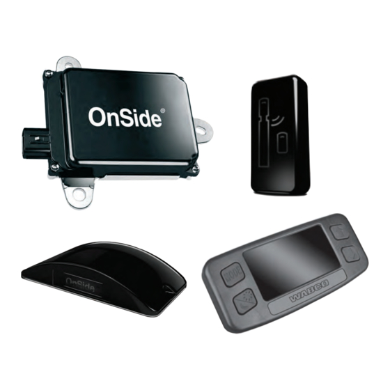
Page 12: System Components
OnSide® BSD Introduction 5.2 System Components 5.2.1 OnSide BSD Radar Sensor Fig. 5.1 4016834a The OnSide BSD system utilizes a 24 GHz short-range radar sensor (Figure 5.1) mounted on the right side of the truck cabin to constantly monitor the vehicle’s passenger side blind spot zone. The radar continuously detects a wide variety of stationary and moving objects in the vehicle’s passenger side blind spot, while the algorithm fi... - Page 13 OnSide® BSD Introduction 5.2.2 OnSide BSD Radar Fascia Fig. 5.3 4016836a The OnSide BSD radar sensor mounts on the passenger side of the truck. When the OnSide BSD radar sensor is mounted on the outside of the fairing or step area, it is covered by a fascia to provide protection against the elements and damage (Figure 5.3).
- Page 14 5.2.4 WABCO OnGuard Display Fig. 5.6 4016839a If the vehicle is equipped with OnGuard and uses the WABCO OnGuard display (Figure 5.6) during the key-on ignition cycle, OnSide should be listed in the WABCO display “SYSTEMS DETECTED” start-up menu (Figure 5.7).
- Page 15 OnSide® BSD Introduction 5.2.5 OnSide BSD Radar Sensor Mounts There are several OnSide BSD radar sensor mounting plates/brackets (Figures 5.9 and 5.10) and spacers depending on the kit that was installed, the radar sensor mounting location, and the vehicle OEM. Your installation may use a spacer of some type.
- Page 16 Fig. 5.14 4016848a Not all vehicles will use the WABCO OnSide BSD harness; some may use an OEM harness. Please see the OEM reference materials for harness information. If the vehicle does use the WABCO OnSide BSD harness (Figure 5.14), it will have the BSD radar sensor connector and BSD LED indicator connector, and the turn signal input relay will be tapped to the harness.
-
Page 17: Diagnostics, Troubleshooting And Testing
Bulb Check or Vehicle Detected Normal or No Vehicle Detected If the vehicle is also equipped with OnGuard and uses the WABCO OnGuard display, during the ignition key-on cycle, "OnSide" should be shown on the display in the "SYSTEMS DETECTED" start-up menu (Figure 6.3). -
Page 18: System Visual Inspection
Fig. 6.5 4016853a For vehicles equipped with a WABCO OnGuard display, when the vehicle is traveling above 15 mph (24.2 km/h), the right turn signal is activated, and a moving vehicle is detected in the blind spot zone, the display will also provide warnings. In addition to the warning from the OnSide BSD LED indicator, there will be an audible chirp heard and a visual "Blind Spot Alert"... -
Page 19: Toolbox™ Software
Confi rm the WABCO display is the correct part number and has the correct software. 6.3 TOOLBOX™ Software WABCO TOOLBOX™ Software version 12.9 or later is the only software that can be used to fully communicate with, and diagnose, the OnSide BSD system. To obtain TOOLBOX™ 12.9 or the latest version of software, visit our website at wabco-na.com. - Page 20 Diagnostics, Troubleshooting and Testing 3. Click on the "Display" heading and select "Diagnostic Trouble Codes" from the drop-down to open the Diagnostic Trouble Code page (Figure 6.9). Fig. 6.9 4016857a When the Diagnostic Trouble Code (DTC) screen opens, all of the DTCs active and stored should populate. The list will provide the DTC "Status", number of "Occurrences", the "SPN", the "FMI"...
-
Page 21: Onside Bsd System Diagnostic Trouble Code Table
The following table provides a list of the OnSide BSD system Diagnostic Trouble Codes (DTCs), troubleshooting and repair instructions. If there is a DTC listed in TOOLBOX™ that is not in the Diagnostic Trouble Code table, contact the WABCO Customer Care Center at 855-228-3203 for assistance. OnSide BSD SYSTEM DIAGNOSTIC TROUBLE CODES... - Page 22 Diagnostics, Troubleshooting and Testing DTC Description DTC Detection Method Action With the ignition on, monitor the voltage (Ignition) at pin 5 of the BSD radar sensor harness connector to determine if the voltage is between 10 and 16 VDC. If the voltage is less than 9VDC: Voltage supply to the radar BSD sensor...
- Page 23 10 times in a row within a corrosion. Off . specifi ed update time. - If all checks are good, contact the WABCO - If the state "Bus Off " is Customer Care Center at 855-228-3203 (United detected on the CAN bus States and Canada);...
-
Page 24: Circuit Descriptions And Diagnostics
OnSide Not Listed in WABCO OnGuard Display "SYSTEMS DETECTED" Start-Up Symptom Chart D Menu. No WABCO OnGuard Display Blind Spot Zone Moving Vehicle Recognition with Symptom Chart E Right Turn Signal Activation (Relay System). No WABCO OnGuard Display Blind Spot Zone Moving Vehicle Recognition with Symptom Chart F Right Turn Signal Activation (J1939 CAN System). - Page 25 Repair any circuit issues in accordance with Check voltage between pin 5 OEM repair guidelines. of the radar sensor harness For any failed WABCO circuit components connector and ground. contact the WABCO Customer Care Center at 855-228-3203 (United States and Canada);...
- Page 26 Repair any circuit issues in accordance with Check voltage between pin 5 OEM repair guidelines. of the radar sensor harness For any failed WABCO circuit components connector and ground. contact the WABCO Customer Care Center at 855-228-3203 (United States and Canada);...
- Page 27 Repair any circuit issues in accordance with connector pin 1 and the OnSide OEM repair guidelines. BSD radar sensor harness For any failed WABCO circuit components connector pin 4 for continuity, Circuit checks Go to Step 7. contact the WABCO Customer Care verify there are no shorts, loose good.
- Page 28 Diagnostics, Troubleshooting and Testing 6.5.2 OnSide BSD System LED Indicator Fig. 6.13 4016861a This simplifi ed diagram (Figure 6.13) represents the OnSide BSD LED indicator circuit. Although they may not be shown here, additional in-line connectors and splices may be present in the circuit depending upon the particular vehicle installation.
- Page 29 Repair any circuit issues in accordance with ohm. OEM repair guidelines. Check resistance between BSD For any failed WABCO circuit components LED indicator harness connector contact the WABCO Customer Care Center pin 2 and ground. at 855-228-3203 (United States and Canada);...
- Page 30 Under or behind the dash for audio warnings only. The exact location of the WABCO OnGuard display on the dash or under/behind the dash may vary slightly based on the installer or OEM. For either confi guration, the display circuit is the same.
- Page 31 The WABCO OnGuard display works intermittently. Inspect the WABCO OnGuard display and connector and verify that they are not loose, and show no sign of damage or corrosion. If the WABCO OnGuard display passes inspection, check the WABCO OnGuard display circuits.
- Page 32 6.5.5 WABCO OnGuard Display Does Not Recognize OnSide If OnSide is the only WABCO system on the vehicle and it is not detected or no WABCO systems are detected, as indicated by the "SYSTEMS DETECTED" screen during start-up, the screen in Figure 6.17 will be displayed.
- Page 33 DETECTED" screen, the display software may be incorrect. To verify the correct display software, turn the ignition on and allow the WABCO OnGuard display to go through its start-up screens process. Once the start-up process is complete, tap the "Mode" button on the display a few times and scroll through the screens until the "SOFTWARE REV"...
- Page 34 Repair any circuit issues in accordance with Check for any Issues with OEM repair guidelines. the J1939 circuit between the For any failed WABCO circuit components WABCO OnGuard display Circuit checks contact the WABCO Customer Care Center harness connector pins 6 and Go to Step 7.
- Page 35 6.5.6 Right Turn Signal Activation Input If the vehicle uses the WABCO OnGuard display, whether on the dash or behind/under the dash, it will need to receive a "Right Turn Signal Activation" signal. This can be performed by the OnSide BSD radar sensor in one of two ways.
- Page 36 See Symptom Chart E. SYMPTOM CHART E NO WABCO OnGuard DISPLAY BLIND SPOT ZONE MOVING VEHICLE RECOGNITION WITH RIGHT TURN SIGNAL ACTIVATION (RELAY SYSTEM) NOTE: Prior to performing the diagnostic steps in the chart below: - Verify that the OnSide BSD LED Indicator functions correctly (bulb check and moving vehicle recognition).
- Page 37 Repair any circuit issues in accordance with Check resistance between relay OEM repair guidelines. socket pin 3/30 and ground. For any failed WABCO circuit components contact the WABCO Customer Care Center at 855-228-3203 (United States and Canada); 001-800-889-1834 (Mexico); or email wnacustomercare@wabco-auto.com.
- Page 38 Check voltage between relay and open OEM repair guidelines. socket pin 2/85 and ground. circuit. For any failed WABCO circuit components contact the WABCO Customer Care Center at 855-228-3203 (United States and Canada); 001-800-889-1834 (Mexico); or email wnacustomercare@wabco-auto.com. If the lamp performance is out of range, does not illuminate, does not alternate, is dim or fl...
- Page 39 OnSide BSD radar sensor sees the right turn signal active in the turn signal switch parameter, it will send a message to the WABCO OnGuard display using the SAE J1939 network to indicate when the right turn signal is activated and a moving vehicle is detected.
- Page 40 NOTE: Prior to performing the diagnostic steps in the chart below: - Verify that the OnSide BSD LED indicator functions correctly (bulb check and moving vehicle recognition). - Verify OnSide is listed the "SYSTEMS DETECTED" screen during the WABCO OnGuard start-up process. - Check for active OnSide BSD DTCs.
- Page 41 Step 10. indicated. TOOLBOX™ Attempt to connect TOOLBOX™ Check for issue with diagnostic device. Check connects to software with other WABCO Go to Step 6. for issue with the vehicle J1939 port and other WABCO systems (ABS or OnGuard). circuit.
- Page 42 LED performs bulb Go to Step 2. Go to Symptom Chart B. bulb check. check. Confi rm that OnSide is shown in the WABCO OnGuard OnSide Display Start up "SYSTEMS Go to Step 3. Go to Symptom Chart D. recognized.
- Page 43 Diagnostics, Troubleshooting and Testing 6.5.6.4 OnSide BSD Radar Sensor Mounting If the OnSide BSD system does not detect moving vehicles in the passenger side blind spot zone when traveling above 15 mph (24.2 km/h) or if the system detects vehicles outside of the blind spot zone, verify that the BSD radar sensor is mounted correctly.
-
Page 44: Component Replacement Procedures
Component Replacement Procedures 7 Component Replacement Procedures 7.1 OnSide BSD Radar Sensor 7.1.1 Exterior Fairing-Mounted Radar Sensor/Fascia Assembly Replacement Fig. 7.1 4016873a Removal 1. Turn the ignition switch to the OFF position. 2. Place blocks under the rear tires to prevent the vehicle from moving. Apply the parking brake. 3. - Page 45 Component Replacement Procedures 4. Place the fascia, radar sensor/bracket assembly, wedge and/or shims assembly together and align the mounting holes with the mounting holes on the fairing. 5. Install the fl at washers on the two M6 fascia mounting bolts. 6.
- Page 46 6. Using the M6 fl anged lock nuts on the back side of the OnSide step mount bracket tighten the 2 M6 mounting bolts to 92 in-lb (10.4 N•m). For more information on the OnSide Step mount assembly refer to TP19022 available at our website: www.wabco-na.com. 7.1.3 OnSide BSD LED Indicator Replacement Fig. 7.3...
- Page 47 Component Replacement Procedures The OnSide BSD LED indicator is mounted on the passenger side A-pillar near the right-side view mirror. (Figure 7.3). The OnSide BSD LED indicator is attached to the passenger side A-pillar using plastic ribbed push rivets. (Figure 7.4). The “Pig Tail” harness cannot be removed from the BSD LED indicator. (Figure 7.5). Fig.
- Page 48 Component Replacement Procedures 7.1.4 WABCO OnGuard Display Replacement 7.1.4.1 On Dash Mounted Display Fig. 7.6 4016878a Removal 1. Turn the ignition switch to the OFF position. 2. Remove the necessary instrument cluster paneling to gain access to the back of the display. Refer to the OEM instructions for correct procedures.
- Page 49 7.1.6 Right Turn Signal Input Relay (If equipped) If the OnSide BSD system uses the WABCO OnSide harness as part of an "aftermarket" or WABCO kit installation, the turn signal input relay will be plugged in to a "socket" style connector that will be taped to the harness.
- Page 50 Component Replacement Procedures...
- Page 51 Component Replacement Procedures...
- Page 52 With its products, the company contributes to reducing emissions and protecting the climate. ZF, which acquired WABCO Holdings Inc. on May 29, 2020, now has 162,000 employees worldwide with approximately 260 locations in 41 countries. In 2019, the two then-independent companies achieved sales of €36.5 billion (ZF) and $3.4 billion (WABCO).
Need help?
Do you have a question about the OnSide MM16167 and is the answer not in the manual?
Questions and answers